
Subscribe to Our Youtube Channel
Related Manuals for ADLINK Technology DLAP-301 Series


Summary of Contents for ADLINK Technology DLAP-301 Series
- Page 1 DLAP-301 Series DLAP-301-JNX / DLAP-301-Nano Edge Inference System User’s Manual Manual Rev.: Revision Date: Sept. 23, 2021 Part No: 50M-00044-1000...
- Page 2 Revision History Revision Release Date Description of Change(s) 2021-09-23 Initial Release Revision History...
-
Page 3: Preface
DLAP-301 Series Preface Copyright © 2021 ADLINK Technology, Inc. This document contains proprietary information protected by copy- right. All rights are reserved. No part of this manual may be repro- duced by any mechanical, electronic, or other means in any form without prior written permission of the manufacturer. - Page 4 Conventions Take note of the following conventions used throughout this manual to make sure that users perform certain tasks and instructions properly. Additional information, aids, and tips that help users perform tasks. NOTE: NOTE: Information to prevent minor physical injury, component dam- age, data loss, and/or program corruption when trying to com- plete a task.
-
Page 5: Table Of Contents
DLAP-301 Series Table of Contents Revision History..............ii Preface ..................iii List of Tables................. vii List of Figures ................ ix 1 Introduction ................ 1 Features................1 Specifications............... 2 Functional Block Diagram............ 4 Mechanical Dimensions............5 External Layout..............6 Pin Definitions..............8 1.6.1... - Page 6 Connecting DC Power ............21 Power Mode Switch ............22 3 Using the System.............. 23 Software Configuration ............23 System Recovery............... 24 DIO Configuration .............. 25 Important Safety Instructions..........27 Getting Service ..............29 Table of Contents...
-
Page 7: List Of Tables
DLAP-301 Series List of Tables Table 1-1: Specifications ............. 2 Table 1-2: Front Panel I/O Connectors & Controls ...... 6 Table 1-3: Rear Panel I/O Connectors ........7 Table 1-4: RJ-45 GbE Pin Definition..........9 Table 1-5: RJ45 PoE Connector Pin Definition......11 Table 1-6: USB 3.0 Pin Definition .......... - Page 8 This page intentionally left blank. viii List of Tables...
-
Page 9: List Of Figures
DLAP-301 Series List of Figures Figure 1-1: Functional Block Diagram........... 4 Figure 1-2: Front View Dimensions..........5 Figure 1-3: Side View Dimensions..........5 Figure 1-4: Front Panel I/O Connectors & Controls ...... 6 Figure 1-5: Rear Panel I/O Connectors ........7 Figure 2-1: Power Mode Switch Jumpers ........ - Page 10 This page intentionally left blank. List of Figures...
-
Page 11: Introduction
DLAP-301 Series Introduction ADLINK’s DLAP-301 Series Edge Inference System leverages the power of NVIDIA® Jetson™ Nano and AGX NX modules to deliver artificial intelligence (AI) at the edge. The DLAP-301 Edge AI Plat- forms with integrated NVIDIA JETSON Nano/AGX NX accelerate... -
Page 12: Specifications
1.2 Specifications DLAP-301-Nano DLAP-301-Nano-L DLAP-301-JNX System Core Processor Jetson Nano Jetson NX Memory eMMC 16GB Display Output Graphic Output 1x HDMI 2.0 Front I/O USB 3.0 1x Type-A USB 2.0 HDMI 1 vertical HDMI connector Rear I/O Ethernet 1x GbE 8x PoE (15W each, 10/100 Ethernet) USB 3.0 2x Type-A... - Page 13 DLAP-301 Series DLAP-301-Nano DLAP-301-Nano-L DLAP-301-JNX Mechanical Dimensions 210mm x 170mm x 55mm Weight Gross 2.5 KG / Net 2.0 KG Mounting Wall mount / DIN rail Environmental Operating Temperature -20°C to 70°C 0°C to 50°C -20°C to 70°C Operating Humidity 95% @40°C (non-condensing)
-
Page 14: Functional Block Diagram
1.3 Functional Block Diagram HDMI2.0 USB 2.0 HDMI Conn HDMI USB0 Micro USB USB Type-A Port 1 USB 2.0 USB 2+3.0 USB1 Genesys 1.8V USB 2+3.0 1x3 Pin/2.54mm USB Type-A Port 2 UART2 USB 3.0 Debug USBSS GL3523 USB 2+3.0 USB Type-A Port 4 CAM_I2C Dual COM port... -
Page 15: Mechanical Dimensions
DLAP-301 Series 1.4 Mechanical Dimensions All dimensions shown in millimeters (mm). Figure 1-2: Front View Dimensions Figure 1-3: Side View Dimensions Introduction... -
Page 16: External Layout
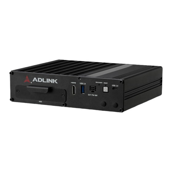
1.5 External Layout Front Panel D E F G H Figure 1-4: Front Panel I/O Connectors & Controls Item Name Description 2.5” SATA drive Removable 2.5” SATA bay for SATA HDD/SSD HDMI port HDMI 2.0 USB 3.0 USB 3.2 Gen1 x1 Type-A Extended Power Molex 4-pin 3.00mm pitch Micro-Fit 3.0 header Switch... -
Page 17: Table 1-3: Rear Panel I/O Connectors
DLAP-301 Series Rear Panel Figure 1-5: Rear Panel I/O Connectors Item Name Description 12V DC connector DC jack See Section 1.6.6 Power Button 8-bit DIO connector PoE connector 8x 10/100M PoE ports supporting 15W each GbE connector GbE from NVIDIA® Jetson™ module (LAN 1) USB 3.0... -
Page 18: Pin Definitions
1.6 Pin Definitions 1.6.1 Ethernet GbE Connectors One Gigabit Ethernet port on the rear panel supports an NVIDIA® Jetson™ Xavier Nx/ Nano LAN connector via Realtek switch con- troller that provides: Full-duplex and half-duplex operation with IEEE 802.3x flow control and backpressure IEEE 802.1Q VLAN support IVL, SVL, and IVL/SVL support Spanning Tree Port Behavior supporting:... -
Page 19: Table 1-4: Rj-45 Gbe Pin Definition
DLAP-301 Series The following table provides details for the RJ-45 GbE pin connec- tions. 10BASE-T/ Pin # 1000BASE-T 100BASE-TX LAN_TX0+ LAN_TX0- LAN_TX1+ — LAN_TX2+ — LAN_TX2- LAN_TX1- — LAN_TX3+ — LAN_TX3- Table 1-4: RJ-45 GbE Pin Definition Introduction... -
Page 20: Power Over Ethernet (Poe)
1.6.2 Power over Ethernet (PoE) The DLAP-301 system supports 8 PoE ports to provide 48V DC at 15W on each port. The 8 Ethernet ports support 10/100M connec- tivity through a Realtek controller to provide: IEEE 802.3/802.3u compatibility Built-in high efficiency SRAM for packet buffer, with 2K- entry lookup table 2048 byte maximum packet length Flow control fully supported... -
Page 21: Usb 3.0 Connectors
DLAP-301 Series The following table provides details for the RJ45 PoE pin connec- tions. 10BASE-T/ Pin # 100BASE-TX — — — — Table 1-5: RJ45 PoE Connector Pin Definition 1.6.3 USB 3.0 Connectors The USB 3.2 Gen1 x1 Type-A connectors are compatible with SuperSpeed, Hi-Speed, Full speed, and Low speed USB devices, suitable for USB peripherals including USB cameras. -
Page 22: Gpio Connector
1.6.4 GPIO Connector The DLAP-301 system supports digital I/O through a 10-pin termi- nal block. The following table provides details for the GPIO pin connections. Signal Name DI4_5V DI3_5V DI2_5V DI1_5V DIO_GND DIO_GND DO4_5V DO3_5V DO2_5V DO1_5V Table 1-7: GPIO Pin Definition Introduction... -
Page 23: Volt Dc Connector
DLAP-301 Series 1.6.5 12 Volt DC Connector The system requires a DC power source with a 4-pin terminal block. Pin Signal ( - ) ( - ) ( + ) ( + ) Table 1-8: 12 Volt DC Connector Pin Definition 1.6.6... -
Page 24: Extended Power Remote Connector
1.6.7 Extended Power Remote Connector The DLAP-301 supports a remote power switch via a Molex 4-pin 3.00mm pitch Micro-Fit 3.0 header. Signal PWR_BTN_LED_C PWR_BTN_REMOTE Pull up (P_5V_A_DIO) Table 1-9: Remote Power Connector Pin Definition Introduction... -
Page 25: Com Port (Serial Port)
DLAP-301 Series 1.6.8 COM Port (Serial Port) The DLAP-301 supports two serial ports. COM1 supports RS-232 and COM2 supports RS-485. RS-232 RS-485 RS485_DN RXDA_DB9 RS485_DP TXDA_DB9 RTSA#_DB9 CTSA#DB9 Table 1-10: RS-232/485 Connector Pin Definition Introduction... -
Page 26: Hdmi Connectors
1.6.9 HDMI Connectors The rear panel supports HDMI 2.0. Pin # Signal Pin # Signal TMDS Data2+ TMDS Data2 Shield TMDS Data2– TMDS Data1+ TMDS Data1 Shield TMDS Data1– TMDS Data0+ TMDS Data0 Shield TMDS Data0– TMDS Clock+ TMDS Clock Shield TMDS Clock–... -
Page 27: Getting Started
DLAP-301 Series Getting Started 2.1 Unpacking Checklist Before unpacking, check the shipping carton for any damage. If the shipping carton and/or contents are damaged, inform your dealer immediately. Retain the shipping carton and packing materials for inspection. Obtain authorization from your dealer before returning any product to ADLINK. -
Page 28: Removing The Chassis Cover
2.3 Removing the Chassis Cover To access the DLAP-301’s internal components, remove the heat- sink as follows. 1. On the front panel, remove all nuts. 2. Remove the front panel, heatsink and SATA drive bay. Getting Started... -
Page 29: Installing A Mini Pcie Wi-Fi Or Lte Module
DLAP-301 Series 2.4 Installing a Mini PCIe Wi-Fi or LTE Module Use the following steps to install a Mini PCIe Wi-Fi or LTE module. 1. Remove the SATA drive bracket. 2. Insert the Mini PCIe Wi-Fi module into the indicated slot at an angle. - Page 30 3. Press down on the module until it is seated, then secure it to the board using two M2.5-P-head-L5 screws (not provided). 4. Attach the wires and antennas that came with your Wi-Fi kit. 5. Reassemble the SATA drive bracket, front panel, and heat- sink.
-
Page 31: Connecting Dc Power
DLAP-301 Series 2.5 Connecting DC Power Before providing DC power to the DLAP-301, ensure the volt- age and polarity provided are compatible with the DC input. Improper input voltage and/or polarity can be responsible for WARNING: system damage. Avant de connecter le PC DLAP-301 à une source de courant continu, veuillez vous assurer de la polarité... -
Page 32: Power Mode Switch
2.6 Power Mode Switch The DLAP-301 supports an extended remote power button. Switch jumper CN25202 to set the power button as remote. Figure 2-1: Power Mode Switch Jumpers Jumper Auto Power On Power button (Default) Remote control Table 2-1: Power Mode Switch Jumper Settings Getting Started... -
Page 33: Using The System
DLAP-301 Series Using the System 3.1 Software Configuration The DLAP-301 ships with a customized NVIDIA Linux for Tegra (L4T) image pre-installed. The latest version of this custom L4T image and other relevant files are available on our website. For the DLAP-301-JNX: https://www.adlinktech.com/Products/... -
Page 34: System Recovery
3.2 System Recovery You will need a Linux host PC (Ubuntu is recommended) in order to flash your client device with a new system image. Complete the following steps on the client before performing the host PC steps. Client (DLAP-301): 1. -
Page 35: Dio Configuration
DLAP-301 Series 3.3 DIO Configuration Use these commands to access DIO control. *: Port 1-4 To write to a specific digital output port: $echo 0 > /sys/class/adlink_DIO/DO_* high $echo 1 > /sys/class/adlink_DIO/DO_* To read from a specific digital input port:... - Page 36 This page intentionally left blank. Using the System...
-
Page 37: Important Safety Instructions
DLAP-301 Series Important Safety Instructions For user safety, please read and follow all instructions, Warnings, Cautions, and Notes marked in this manual and on the associated device before handling/operating the device, to avoid injury or damage. S'il vous plaît prêter attention stricte à tous les avertissements et mises en garde figurant sur l'appareil , pour éviter des blessures... - Page 38 A Lithium-type battery may be provided for uninterrupted backup or emergency power. Risk of explosion if battery is replaced with one of an incorrect type; please dispose of used batteries appropriately. Risque d’explosion si la pile est remplacée par une autre de CAUTION: type incorrect.
-
Page 39: Getting Service
D-68163 Mannheim, Germany Tel: +49-621-43214-0 Fax: +49-621 43214-30 Email: emea@adlinktech.com ADLINK Technology, Inc. (UK Liaison Office) First Floor West Exeter House, Chichester Fields Business Park Tangmere, West Sussex, PO20 2FU, United Kingdom Tel: +44-1243-859677 Email: uk@adlinktech.com Please visit the Contact page at www.adlinktech.com...
Need help?
Do you have a question about the DLAP-301 Series and is the answer not in the manual?
Questions and answers