
Related Manuals for Tiso Sesame Gate-W


Summary of Contents for Tiso Sesame Gate-W
- Page 1 "TiSO-PRODUCTION" LTD FULL-HEIGHT TURNSTILE WITH SERVO DRIVE single «Sesame Gate-W» of AUIA.439 FULL-HEIGHT TURNSTILE WITH SERVO DRIVE OPERATION AND INSTALLATION MANUAL rev.1.0 2022 UKRAINE...
-
Page 2: Table Of Contents
5. STORAGE AND TRANSPORTATION ......................27 6. DISPOSAL CONSIDERATIONS ........................27 Annex А. Overall and installation dimensions of the Full-Height Turnstile SESAME GATE-W ......28 Annex B. Control panel AUIA.114.02.00.00 ......................29 Annex C.1 - Wiring diagram of the turnstile connection ..................30... -
Page 3: Customer Warnings On Safe Operation Of The Turnstile
This Operation Manual (hereinafter referred to as OM) covers the with servo drive indoor (or outdoor) single full- height turnstiles "SESAME GATE-W" (hereinafter referred to as the "turnstile"). The Operation Manual contains information about design, specifications, installation for proper operation and maintenance of the turnstile. -
Page 4: Description And Operation
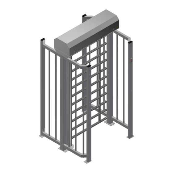
Operation Manual 4 1. DESCRIPTION AND OPERATION 1.1. General Information and Purpose The turnstile is designed for pedestrian movement control at access points of industrial enterprises, banks, stadiums, administrative facilities etc. and outdoor due to command signals of access control system (from keypad, proximity card readers) or manually (from manual control panel). -
Page 5: Design And Operation
7. Card reader location 8. Container locks; Fig.1 – Design and general appearance of the single turnstiles with pedestrian gate «SESAME GATE-W» - is not included in the turnstile scope of delivery - to be equipped by the customer on recharge basis, when... -
Page 6: The Pedestrian Gate Control Mechanism Design Is Shown In Figure 3
8 –Additional electronic control unit; Fig. 2 – Design and general appearance of the container «SESAME GATE-W» 1.4.2. The pedestrian gate control mechanism design is shown in Figure 3 One servo drive provides rotation of the gate to one or the other side at 90° angle and automatic bringing to the initial position after the gate access. -
Page 7: Principle Of The Turnstile Operation
Operation Manual 7 Top view Bottom view 1 – gear motor; 6 – mechanism housing ; 2 – position sensor; 7 – latches; 3 – locking solenoid NO (left); 8 - mechanism connection plug. 4 – locking solenoid NC (right); 9 –... -
Page 8: Description And Operation Of Controller As An Integral Component Of The Turnstile
Operation Manual 8 1.5. Description and operation of controller as an integral component of the turnstile 1.5.1. Turnstile controller РСВ.112.21.20.01 1.5.1.1 Purpose of controller РСВ.112.21.20.01 The controller РСВ.112.21.20.01 is designed for control of the full-height turnstile operation both under control of authorized access system (hereinafter referred to as AAS) and independently. - Page 9 Operation Manual 9 On the board there are 13 jumpers, 40 terminal clamps for connection of wires, 14 of them for external connections, another- for connection to the turnstile units or can be standby. Application of jumpers on the controller board PCB.112.21.20.01: CONTROLLER PCB 112.21.20.01 Table 3 - Application of jumpers...
- Page 10 Operation Manual 10 1.5.1.2. Technical features of controller РСВ.112.21.20.01 The controller technical features are specified in Table 4. Table 4- The controller technical features Parameter value Parameter description Number of inputs for reception of control commands Number of signal outputs Input type logical Output type...
- Page 11 Operation Manual 11 - when gate rotates to 60º, after reaching this point, the signal "A/B PASSAGE DETECTION" appears («OUT3» or «OUT4»); - when gate rotates to <60º, after reaching this point by the gate, when closing, the "A/B PASSAGE DETECTION"...
- Page 12 Operation Manual 12 Continued table 5 Signal is generated by controller OUT6 ХТ2/7 EXIT when violation of operation logic is ("ERROR") detected Signal is generated by controller OUT7 ХТ2/8 EXIT when "PANIC" function is turned on ("PANIC") ХТ3/1 OPTO1 ENTRY 1) Logical «0»...
-
Page 13: Pedestrian Gate Motorized Mechanism Controller Рсв.201.01.00.01
Operation Manual 13 1.5.2 Pedestrian gate motorized mechanism controller РСВ.201.01.00.01 1.5.2.1 Purpose of motorized mechanism controller РСВ.201.01.00.01 The controller is designed for acquisition of commands from the turnstile controller PCB.112.21.20.01 and generation of the motor and motorized mechanism locking solenoid control signals. The controller is assembled on the 85x70 mm board, on which electric components and connectors for external connection 13 LEDs are installed on controller board. - Page 14 Operation Manual 14 The purpose of controller РСВ.201.01.00.00 (for pedestrian gate motorized mechanism) contacts designed for connection of peripherals is shown in Table 7 Table 7 Connector/ Signal parameters Direction Designation Purpose contact No and description Command "PEDESTRIAN GATE TO X1/1 «TO BE OPENED ENTRY...
-
Page 15: Detecting The Actual Passage Of A Person Through The Turnstile
Operation Manual 15 1.5.3. Detecting the actual passage of a person through the turnstile. 1.5.3.1. Description of elements of the scheme for detecting the actual passage of a person through the turnstile. А10. Controller PCB103 – which analyzes signals from human presence sensors, receives input signals from the turnstile controller PCB112 and issues output signals to other circuit elements. - Page 16 Operation Manual 16 1.5.3.2 Controller РСВ.103 Purpose of controller РСВ.103 The controller РСВ.103 is designed for the operation with human detection sensors in the turnstile passage. It is placed in a Electronic control unit for additional options Description of controller РСВ.103 The controller PCB103 reads the distance measured by the 3 sensors (Sensor 1 - Sensor 3) to the person who passing through the gate portal of...
- Page 17 Operation Manual 17 The purpose of the controller’s contacts designed for connection of peripherals is specified in Table 11 Connector/ Signal parameters Direction Designation Purpose contact No and description Not Used XT3/1 XT3/2 (common) 1) power supply voltage «+» power supply (controller energization) XT3/3 2) consumption current <...
-
Page 18: Intended Use
Operation Manual 18 INTENDED USE 2.1. Operation limitations 2.1.1 The product should be operated under the conditions specified in 1.3 of this document, while keeping the specifications given in section 1. 2.1.2 Do not operate the turnstile with: – the presence of mechanical gritting in the moving parts of the turnstile; –... - Page 19 "CLOSED" turnstile mode. Fig.9 - General view of the "SESAME GATE-W" turnstile installation in the design position...
- Page 20 4) Installation of additional components Installation of additional components of the "SESAME GATE-W" full-height turnstile is possible (See Figure 11) (They are not included in the turnstile scope of delivery - to be equipped by the customer on recharge basis, when applicable).
- Page 21 Operation Manual 21 5) Installation of proximity card reader upon the availability of Access Control System (ACS) - The holes (3) to be made in the access way wall butt (See Figure 12) next to LED display according to the card reader size chosen by the customer.
-
Page 22: Preparation For Use
Operation Manual 22 Fig.13 – Electronic control unit - turnstile connection Fig.14 – Electronic Addition control unit Connection of additional turnstile options (See Figure 14): c) Connection cable from ACS (See Annex C Table 8-9); d) Connection cable to ACS (See Annex C); i) The turnstile performance to be checked. -
Page 23: Actions In Extreme Conditions
Operation Manual 23 Continued table 12 Free access in FREE button Green arrow Make sure that pedestrian gate opens one direction pushed for access in authorized free access to 90º in free access direction at every chosen direction ("A" or is blinking in chosen push and remains open for ~10 s and "B") -
Page 24: Maintenance
Operation Manual 24 In case of turnstile power failure, emergency mode (fail safe) will be activated and gate will be unlocked in two directions automatically- i.e. free to open in any direction, After turning off the alarm or deactivating the panic mode from the control panel, the gate are restored to their initial position automatically. -
Page 25: Routine Maintence
Operation Manual 25 Table 14 - Periodic maintenance by technical staff Component Period Action Fixation screws 6 months Checking/Tightening Mechanical screws 6 months Checking/Tightening Actuator 12 months Control Controller 12 months Checking + Cleaning Sensors (position / speed / IR) 6 months Checking + Cleaning Cable joints and sockets... -
Page 26: Procedure Of The Turnstile Gate Zero Position Setting
Operation Manual 26 Continued table 15 Control panel beeps Control panel have Check the wires "Communication" communication with the controller Check the control panel Check the controller Change the controller/ control panel The Indication does not work Have no a communication with the Check the wires controller Check the LED indicator... -
Page 27: Storage And Transportation
Operation Manual 27 10) The turnstile to be energized; 11) Turnstile operation to be checked 12) New zero position setting is completed; Fig. 16 – Magnetic sensor board PCB 730.01 Gap between magnetic axis1 and magnetic Top view of the installed Layout board over... -
Page 28: Annex А. Overall And Installation Dimensions Of The Full-Height Turnstile Sesame Gate-W
Annex А. Overall and installation dimensions of the Full-Height Turnstile SESAME GATE-W... -
Page 29: Annex B. Control Panel Auia.114.02.00.00
Annex B. Control panel AUIA.114.02.00.00 1 – control panel body; 5 – "FREE ACCESS" mode control button 2 – "SINGLE ACCESS" control button 6 – "PANIC" mode control button mode control button 3 – front plate; 7 – access direction LED display; 4 –... -
Page 30: Annex C.1 - Wiring Diagram Of The Turnstile Connection
Annex C.1 - Wiring diagram of the turnstile connection... -
Page 31: Annex C.2 - Wiring Diagram Of The Turnstile Connection To Acs, Fa And Control Panel
Annex C.2 - Wiring diagram of the turnstile connection to ACS, FA and control panel... - Page 32 Manufacturer: LLC TiSO-PRODUCTION 14, Promyslova Street, Kyiv, 02088, Ukraine Phone: +38 (044) 291-21-11 Tel./fax: +38 (044) 291-21-02 E-mail: sales@tiso.global www.tiso.global SERVICE CENTER e-mail: service1@tiso.global Our equipment meets the requirements of European standards: EN ISO 12100:2010, EN ISO 14118:2018, EN 60204-1:2018, EN ISO...
Need help?
Do you have a question about the Sesame Gate-W and is the answer not in the manual?
Questions and answers