Table of Contents
Advertisement
Quick Links
MANUAL
USER
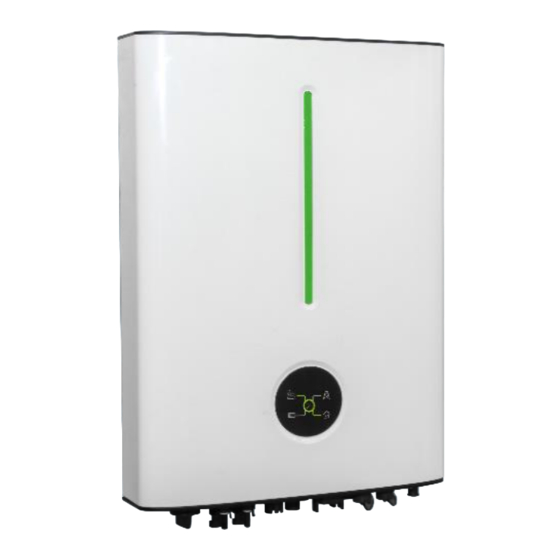
Hyper 3~6kW
Copyright Declaration
The copyright of this manual belongs to Hangzhou Livoltek Power Co.,Ltd.. Any corporation or
individual should not plagiarize, partially or fully copy and no reproduction or distribution of it in
any form or by any means. All rights reserved.
LV1P6521-EN-V08-2405
Advertisement
Table of Contents


Need help?
Do you have a question about the Hyper-2000 and is the answer not in the manual?
Questions and answers