Table of Contents
Advertisement
USER MANUAL
Hyper 3~5kW
Copyright Declaration
The copyright of this manual belongs to Hangzhou Livoltek Power Co., Ltd. Any
corporation or individual should not plagiarize, partially or fully copy and no reproduction
or distribution of it in any form or by any means. All rights reserved.
HP16521-Ver 10-2204
Advertisement
Table of Contents

Related Manuals for LIVOLTEK Hyper 3000


Summary of Contents for LIVOLTEK Hyper 3000
- Page 1 Hyper 3~5kW Copyright Declaration The copyright of this manual belongs to Hangzhou Livoltek Power Co., Ltd. Any corporation or individual should not plagiarize, partially or fully copy and no reproduction or distribution of it in any form or by any means. All rights reserved.
-
Page 2: Table Of Contents
Content About This Manual ................4 Validity .................. 4 Target Group ................. 4 Symbol Used ................4 Storage of the manual ............4 Safety Precautions ................5 Personnel Requirements ............5 Inverter Safety ............... 5 Battery Safety ................ 6 Installation Safety ..............7 Electrical Safety .............. - Page 3 6.5 PV Cable Connection ..............39 6.6 Battery Connection ..............41 6.7 WIFI / 4G Connection (Optional) ..........45 6.8 DRM Connection ................ 46 6.9 Multi COM Terminal Connection ..........47 6.10 Installation Verification ............53 System Operation ................54 7.1 LEDs Display ................
-
Page 4: About This Manual
1.1 Validity Thank you for choosing our low-voltage hybrid inverter. This manual is valid for the following models: Hyper 3000, Hyper 3680, Hyper 4600, Hyper 5000 1.2 Target Group This manual is intended for qualified persons and inverter owners. All activities... -
Page 5: Safety Precautions
Safety Precautions The inverter has been designed and tested strictly in accordance with international safety regulations. As with all electrical or electronical devices, there are residual risks despite careful construction. Read all safety instructions carefully prior to any work and observe them at all times when working on or with the inverter to prevent personal injury and property damage and to ensure long-term operation of the inverter. -
Page 6: Battery Safety
WARNING Danger to life due to fire or explosion In rare cases, an explosive gas mixture can be generated inside the product under fault conditions. In this state, switching operations can cause a fire inside the product or explosion. Death or lethal injuries due to hot or flying debris can result. •... -
Page 7: Installation Safety
• The safety instructions in this manual cannot cover all the precautions that should be followed. Perform operations considering actual onsite conditions. • LIVOLTEK shall not be held liable for any damage caused by violation of the safety instructions in this manual. -
Page 8: Maintenance And Replacement
• All electrical connections must be in accordance with local and national standards. Only with the permission of the local utility grid company, the inverter can be connected to the utility grid. 2.6 Maintenance and Replacement DANGER • High voltage generated by the equipment during operation may cause an electric shock, which could result in death, serious injury, or serious property damage. -
Page 9: Product Introduction
Product Introduction 3.1 Function Description • LIVOLTEK Hyper Series, also called hybrid inverters, are applicable to both on- grid and off-grid solar system with participation of PV array, battery, loads and grid system for energy management. • The inverter converters the DC power from the PV array or the battery to the AC power. -
Page 10: Appearance
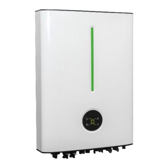
3.2 Appearance Figure 1. Appearance Position Designation Battery SOC indicator: Indicates the SOC status of the connected lithium battery. Inverter LED indicator: Displays the current operating status of the inverter Nameplate Label: Clearly identify the product, including the SN, technical data, certifications, etc. Figure 2. - Page 11 Figure 3. Terminals on the inverter Position Description DC Switch (Optional) PV Inputs(one or two pairs, depending on the model) Grid output for connection to the utility grid MULTI COM Port for CT/PA/EV connection DRM Port BMS Port Battery Connectors EPS Output for backup loads Communication Port for Wi-Fi /4G (Optional) Stick Additional Grounding terminal...
-
Page 12: System Diagram
3.3 System Diagram Mobile APP Grid Communication Billing Internet Battery Meter Hybrid Smart Loads PV Array Meter or CT Router Inverter... -
Page 13: Work Modes
3.4 Work Modes The hybrid inverter offers four operating modes (Self-use, Self-define, backup and off- grid) that can be configured via LIVOLTEK APP for you to determine which mode will be best for you. Modes Description Self-Use (Default) •The energy produced by the PV system will go for loads... - Page 14 Notes: *1: The inverter offers an export limitation function for you to decide whether you have a grid limitation, and specify its value via LIVOLTEK APP. The export power should not be more than the limit value set in commissioning...
- Page 15 *1: Firmware update may be required to support this mode. *2: You can choose whether to import from the grid to charge the battery via the LIVOLTEK APP. *3: You can choose whether to export to the grid from the battery via the LIVOLTEK APP. 3.4.3 On-Grid Backup Mode •When operating in this mode, solar energy and grid will fully charge battery as first...
- Page 16 priority at the same time. •The loads will be supplied by the surplus solar production supplemented, if necessary by the public electricity grid. The battery will be used only when the grid failure. NOTICE •If set zero feed-in, the system will not export power to grid when work on the mode of self-use, self-define or backup.
-
Page 17: Unpacking And Storage
Unpacking and Storage The inverter is thoroughly tested and strictly inspected before delivery. Damage may still occur during shipping. Please check the outer packing for damage and the inner contents for any visible damage. Contact your distributor immediately in case of any damaged or missing components. - Page 18 Position Designation Inverter Inverter Bracket (Split Application) EPS Plug for backup loads (critical Loads) AC Plug for Grid Positive & Negative PV Plugs (Two pairs) Wi-Fi & Bluetooth integrated Stick CT(Current Transformer) & CT cable 16pin COM connector for CT/Parallel/EV charger Positive &...
-
Page 19: Identify The Inverter
4.2 Identify the Inverter 4.2.1 Nameplate After moving the hybrid inverter from package, identify it by reading its nameplate labeled on the side of the inverter. The nameplate contains important product information: the model information, technical specifications and compliance symbols. Take Hyper 5000 as an example. - Page 20 4.2.2 Compliance and Safety Symbols Symbol Explanation CE marking The product complies with the requirements of the applicable EU directives. UKCA marking The inverter complies with the requirements of the applicable UKCA guidelines. UKNI marking The inverter complies with the requirements of the applicable UKNI guidelines.
- Page 21 4.3 Storage of Inverter The following requirements should be met if the inverter will not be deployed immediately: •Do not unpack the inverter (put desiccant in the original box if the inverter is unpacked). •Store the inverter at a temperature range of -30° C to +70° C, and with the relative humidity of 0% to 100% (no condensing).
-
Page 22: Mechanical Installation
Mechanical Installation 5.1 Installation Requirements NOTICE • Make sure there is no electrical connection before installation. • In order to avoid electric shock or other injury, make sure that holes will not be drilled over any electricity or plumbing installations. •... - Page 23 5.1.2 Environment Requirements The inverter must be installed in a ventilated environment to ensure good heat dissipation. Make sure the installation meets the following conditions: •Not in areas where highly flammable materials are stored. •Not in potential explosive areas. •Not in the cool air directly. •Not near the television antenna or antenna cable.
-
Page 24: Installation Instruction
• For Split Application, the inverter can be matched with low voltage lithium battery from LIVOLTEK or Pylon or Lead acid battery. • For All-in-one Application, the inverter must be matched with LIVOLTEK lithium battery, and also need purchasing a Middle Cover Kit which can help hiding the wires to make the whole system tidy and safe. - Page 25 5.2.1 Installing the Inverter (Split Application) Step1: Drill holes on the wall • Take out the wall-mounting Bracket from the inverter package. • Locate the appropriate drilling holes and mark it with a marker pen (Using a digital level to make sure the bracket is at a horizontal position before installation.) •...
- Page 26 5.2.2 Installing the All-in-one System Step1: Choose a location • Choose an appropriate location capable of supporting the full weight (>90kg) and height of All-in-one system. • Be sure to choose a flat wall. Step 2: Take out the Brackets •...
- Page 27 Step 3: Assemble the All-in-one Mounting Bracket • Assemble the All-in-one Mounting Bracket with 4 screws as shown below. Step 4: Anchor All-in-one Mounting Bracket • Determine the positions for drilling holes using the marking-off template, and then mark the positions with a marker.
- Page 28 Step 5: Secure the All-in-one bracket on the wall • Fix the All-in-one bracket to the wall with 9 expansion bolts. Step 6: Remove the upper cover of the Battery •Pull out the front cover of the wiring area, then loosen the screws on the top cover to remove the upper cover of the battery.
- Page 29 Step 8: Install the bottom of middle cover kit to the Bracket •Install the bottom of middle cover kit to the all-in-one bracket and tighten the screws (M5*5). Step 9: Install the Inverter to the Bracket •Lift and hang the Inverter to the bracket and secure with screw. •Make sure that 2 mounting ears are perfectly engaged with the bracket.
- Page 30 cover bottom. Then tighten them with M5 screws. Step 11: Electrical Connection Please refer to the Electrical Connection instructions in the next chapter. Step 12: Install the Middle-cover •Buckle the middle-cover to the all-in-one system after all electrical connection and settings are done •DO NOT forget to grounding the Inverter and battery.
-
Page 31: Electrical Connection
Electrical Connection Prior to any electrical connections, keep in mind that the inverter has dual power supplies. It is mandatory for the qualified personnel to wear personal protective equipment (PPE) during the electrical work. DANGER Danger to life due to a high voltage inside the inverter! •... -
Page 32: Wiring Diagram
6.1 Wiring Diagram 6.1.1 Wiring Diagram for European... - Page 33 6.2 Wiring Diagram for Australia and New Zealand WARNING • In Australia and New Zealand, electrical installation and maintenance shall be conducted by a licensed electrician and shall comply with Australia/New Zealand National Wiring Rules. • Because the inverter does not maintain neutral integrity, an external neutral connection must be used in Australia and New Zealand.
-
Page 34: Additional Grounding Connection
6.2 Additional Grounding Connection WARNING • Ensure that the PE cable is securely connected. Otherwise, electric shocks may occur. • Do not connect the neutral wire to the enclosure as a PE cable. Otherwise, electric shocks may occur. • Good grounding for the inverter helps resist the impact of surge voltage and improve the EMI performance. -
Page 35: Grid Cable Connection
the cable with a screwdriver. • Apply paint to the grounding terminal to ensure corrosion resistance. 6.3 Grid Cable Connection The hybrid inverter has two AC output terminals, one is grid output for connecting grid and the other is EPS (emergency power supply) output for connecting critical loads. ON Grid Output OFF Grid Output for critical loads WARNING... - Page 36 Grid and EPS output terminals show as below: Back shell Cable nut Threaded sleeve Connection terminal WARNING • The grid voltage and frequency must be in the permissible range. • An external AC breaker must be installed on the AC side of each inverter to ensure that the inverter can be safely disconnected from grid when necessary.
-
Page 37: Critical Loads Connection (Eps Function)
Step 2: Connecting AC Connector • After AC wiring, route the AC connector into the AC terminal of the inverter and double check it. Connect “PE” conductor to the grounding • electrode. Connect “L” and “N” conductors to the AC circuit breaker. •... - Page 38 Step 2: Connecting EPS Connector • Unscrew the cap on the EPS port. • Insert the EPS cable into the EPS port on the inverter until there is a “Click” sound. 6.4.2 Declaration for EPS Loads The purpose of the EPS Loads Function is to enable certain house circuits to remain on in the event of a power failure.
-
Page 39: Pv Cable Connection
NOTICE • Appliances such as air conditioner are required at least 2~3 minutes to restart because it's required to have enough time to balance refrigerant gas inside of circuits. If a power shortage occurs and recovers in a short time, it will cause damage to your connected appliances. - Page 40 • To ensure IP65 protection, use the right PV plugs in the package. • Damage to the device due to the use of incompatible terminals shall not be covered by the warranty. • All wiring must be performed by a qualified personnel. Suggested cable requirement for PV wires Model Wire Size...
-
Page 41: Battery Connection
Step 2: Installing the PV Connectors • Check the positive and negative polarity of the PV strings. • Connect the PV connectors to the corresponding terminals until a “click” sound is heard. • Seal the unused PV terminals with the terminal caps. 6.6 Battery Connection Refer to the instructions supplied by the battery manufacturer for the connections on the battery side. - Page 42 NOTICE • This inverter can only be connected with LIVOLTEK or Pylon low-voltage lithium batteries with nominal voltage from 40V to 60V now. If you choose other lithium batteries, please consult LIVOLTEK for compatibility. Otherwise inverter will not work normally.
- Page 43 Communication interface between inverter and battery is CAN with a RJ45 connector. • The CAN cable enables the communication between the inverter and the Li-ion battery from Pylon (48V), LIVOLTEK. • The battery communication can only work when the battery BMS is compatible with the inverter.
- Page 44 6.6.2.2 BMS Pin Definition NOTICE • The BMS Pin Definition for battery from the Pylontech and LIVOLTEK are different. Make sure the right wire sequence, otherwise will cause failure. BMS Pin Definition for LIVOLTEK Lithium Battery BMS Pin Definition for Pylontech Lithium Battery...
-
Page 45: Wifi / 4G Connection (Optional)
6.6.3 NTC Communication for Lead-acid battery (Optional) The lead acid battery controls the inverter charging and discharging by NTC temperature sensing. Procedure: Step 1: Please find the NTC cable and a piece of tape in the accessories package of inverter. Step 2: Make the tape adhere to NTC interface. -
Page 46: Drm Connection
Step 3: Remove the cable jacket and strip the wire insulation. Step 4: Plug the wires into the corresponding terminals. Step 5: Fasten the swivel nut with a torque of 4–5N.m and connect the other end to the DRED (DRED device is not provided by LIVOLTEK). -
Page 47: Multi Com Terminal Connection
6.9 Multi COM Terminal Connection The inverter provides 16pin terminals to facilitate you to install CT or Smart meter, parallel function or EV charger. Follow the pin definition below to connect the Multi com communication cables. Do not remove the resistor or short circuit wire unless you are going to use the corresponding PINs. - Page 48 Wiring Connection Procedure Notes: Assemble the communication module and plug it into the communication terminal directly if you are not going to use the communication functions. Step 1: Prepare the communication cable and remove the plug of the communication terminal. Step 2: Dismantle the communication module and take out the pin terminal.
- Page 49 LIVOLTEK or buy it yourself. • The smart meter must be authorized by LIVOLTEK, any third party or non- authorized meter may not match with the inverter. LIVOLTEK will not take the responsibility if the meter is unavailable. NOTICE •...
- Page 50 • Please use the smart meter cable in the accessory box for communication. Wiring Connection Procedure Step1: Assembling the BMS cable Connector Make LAN cable with RJ45 terminal. Thread the swivel nut over the LAN cable. Press the cable support sleeve out of the cable gland. Remove the filler plug from the cable support sleeve.
- Page 51 Procedure Step 1 Connect the signal cable to the signal cable connector. Step 2 Connect the signal cable connector to the COM port. Step 3 Securing the signal cable connector...
- Page 52 6.9.4 EV charger Connection This inverter is ready for you to use solar energy to charge your electric car. For specific operations, please refer to the LIVOLTEK EV charger user manual. Notes: This inverter can only be connected with LIVOLTEK EV charger now.
-
Page 53: Installation Verification
6.10 Installation Verification Check the following items after the inverter is installed. • No other objects put on the inverter. • All screws especially the screws used for electrical connections are tightened. • The inverter is installed correctly and securely. •... -
Page 54: System Operation
No fault occurs Green/Red blink System startup or updating You can monitor & set data of the inverter through the LIVOLTEK APP. For details about operation, refer to APP User Manual. APP User Manual is available for free from website. - Page 55 LED indicator status for common fault of the inverter: Error Message BATTERY GRID LOAD SYSTEM FAULT ★ ★ Starting up ● ◎ ◎ ◎ ◎ Normal status WI-FI ● ◎ ◎ ◎ ◎ communication ● ◎ ◎ ◎ ◎ PV energy weak ●...
-
Page 56: System Commissioning
Step 5: Configure the Wi-Fi stick • Establish communication connection between the mobile phone and Wi-Fi stick, then set initial protection parameters. Refer to LIVOLTEK APP Operation Instructions for details. Step 6: Self-test in accordance with CEI 0-21 (Italy Only) •... -
Page 57: System Decommissioning
• Please use the LIVOLTEK APP to initiate the self-test procedure and get the test results. Refer to “Settings on the APP” for details. Step 7: Observe the LED indicator • Observe the LED indicator to ensure that the inverter operates normally. -
Page 58: Settings On The App
Settings on the APP 8.1 User Interface Introduction... -
Page 59: Download And Install
Make sure the Wi-Fi stick is connected to the inverter and the network is configured. Procedure: Method 1: Search for the keyword "Livoltek" from Google Play Store or Apple AppStore, download and install the latest version of the monitoring software for free. -
Page 60: Troubleshooting And Maintenance
Troubleshooting and Maintenance WARNING • Before maintaining and commissioning inverter and its peripheral distribution unit switch off all the charged terminals of the inverter, and wait at least 10 minutes after the inverter is powered off. 9.1 Troubleshooting When the inverter has an exception, its basic common warning and exception handling methods are shown in the table below. - Page 61 Output Voltage abnormal Check if the load power is within the EPS EPS Volt Fault (Inverter voltage is higher than power range and the AC output wires are 260Vac) connected well. Reduce the connected load by switching off Overload error. The inverter is some equipment, and wait for the recover.
-
Page 62: Maintenance
Check the parallel communication cable and adjust it if need. Communication faults between PAL Com Fault Restart the inverter and contact your dealer the master and the slave inerter. for technical support if the error happens again. The master-slave identity of the Check the number of the inverters and adjust PAL Multi Master inverter is set incorrectly. -
Page 63: Removing The Inverter
Check Item Method Period System clean Check the temperature and dust of the inverter. Clean the inverter enclosure if necessary. System running Check whether the inverter is not damaged or status deformed or can be operated with no abnormal sound. Once Cable entry Check whether the cable entry is insufficiently sealed,... -
Page 64: Technical Data
Technical Data Hyper- Hyper- Hyper- Hyper- PV Input Data 3000 3680 4600 5000 Max. PV Input Power (Wp) 4500 5520 6900 7500 Max. PV Input Voltage (V) Nominal DC Input Voltage (V) MPPT Voltage Range (V) 125~550 No. of MPPTs/Strings per MPPT 1 / 1 2 / 1 2 / 1... - Page 65 Euro Efficiency (%) 97.1 97.4 Protection DC Switch Integrated PV Reverse Polarity Protection Integrated Output Over Current Protection Integrated Output Short Circuit Protection Integrated Output Over Voltage Protection Integrated Anti-islanding Protection Integrated Insulation Resistor Detection Integrated Residual Current Detection Integrated Ground Fault Monitoring Integrated General Data...
-
Page 66: Disclaimer
Inverter is changed, updated or disassembled on hardware or software without authority from LIVOLTEK. • Obtain the communication protocol from other illegal channels. • Build monitoring, control system without authority from LIVOLTEK. • LIVOLTEK will keep right to explain all the contents in this user manual. - Page 67 Warranty Card Registration Dear customer, thank you for choosing LIVOLTEK product. For registering product warranty, please prepare everything ready and register on https://www.livoltek.com/registration.html. Product Information Product Type Product S/N Installation date Installation Company Personal Information Your name Your contact number...
- Page 68 Contacts Hangzhou LIVOLTEK Power Co., Ltd Address: 1418-35 Moganshan Road, Hangzhou, 310011, China Tel: +86-571-28330320 Fax: +86-571-28020357 Email: info@LIVOLTEK.com Web:www.livoltek.com...
Need help?
Do you have a question about the Hyper 3000 and is the answer not in the manual?
Questions and answers