Table of Contents
Advertisement
Quick Links
The Perlick Corporation verifies this product does not contain a prohibited refrigerant as defined by the California Air Resource Board (CARB),
the state of New York, and any other state with HFC prohibition laws. This product does not contain HFC's. The following disclosure statement is
provided to comply with the CARB regulation:
This equipment is prohibited from use in California with any refrigerants on the "List Of Prohibited Substances" for that specific end use, in
accordance with the California Code of Regulations, title 17, section 95374. This disclosure statement has been reviewed and approved by the
Perlick Corporation and the Perlick Corporation attests under penalty of perjury, that these statements are true and accurate.
Installation &
Operation Manual
Refrigeration
For all second generation
Column
column refrigeration
produced after 7/21/24
CC24B-2
CC30B-2
CR24B-2
CR30B-2
CC24C-2
CC30C-2
CR24C-2
CR30C-2
CC24D-2
CC30D-2
CR24D-2
CR30D-2
CC24W-2
CC30W-2
CR24W-2
CR30W-2
C
US
Form No. Z3006
Rev. 07.18.24
Advertisement
Table of Contents

Related Manuals for Perlick CC24B-2


Summary of Contents for Perlick CC24B-2
- Page 1 CR30W-2 The Perlick Corporation verifies this product does not contain a prohibited refrigerant as defined by the California Air Resource Board (CARB), the state of New York, and any other state with HFC prohibition laws. This product does not contain HFC’s. The following disclosure statement is provided to comply with the CARB regulation: This equipment is prohibited from use in California with any refrigerants on the “List Of Prohibited Substances”...
-
Page 2: Table Of Contents
To register your product, visit our web site at column refrigerator. This manual has been prepared perlick.com. Or scan QR code located next to the to assist you in the installation of your cabinet and to product identification plate located behind the toe acquaint you with its operation and maintenance. -
Page 3: Safety Precautions/Site Preparation
For more information on whether a product in this list contains these chemicals, please refer to the specific product page at perlick.com. Or to find out more about Prop 65, go to P65Warnings.ca.gov. -
Page 4: Prior To Installation
84" 83 11/16" repair work must be of operation. The outlet should be placed in the performed by a Perlick authorized servicer. hatched area dimensioned below. Work done by unqualified individuals could Electrical Supply 115V, 60Hz, 1 Phase, 3.2 Amps potentially be dangerous and will void the warranty. -
Page 5: Installation
OPENING DIMENSIONS - SINGLE UNIT hours before connecting the unit. Failure to do so can affect the function and performance of the appliance. The depth of each Perlick column is 24” (610). Allow for panel thickness when planning the finished CAUTION This appliance should be installed opening depth. - Page 6 When building into structure or next to adjacent walls reference this drawing for minimum required clearances to avoid interference when opening the door(s). The adjacent structure clearances indicated are based on a standard perlick handle installed on the door overlay.
- Page 7 Column Refrigeration Installation & Operation Manual INSTALLATION CONTINUED MINIMUM SPACING REQUIRED BETWEEN ADJACENT CABINETS TO AVOID DOOR SWING INTERFERENCE CONTINUED. Opening Dimensions (C) 2 Cabinets HANDLE TO HINGE. Refer to (C) Opening diagram (page 8) for finished opening dimensions and outlet locations. (D) 3 Cabinets with Hinges either all left or all right.
- Page 8 Column Refrigeration Installation & Operation Manual INSTALLATION CONTINUED MINIMUM SPACING REQUIRED BETWEEN ADJACENT CABINETS TO AVOID DOOR SWING INTERFERENCE CONTINUED. (G) 3 Cabinets with Hinges Right-Left-Left or Left-Right-Right. Refer to (G) Opening diagram (page 9) for finished opening dimensions and outlet locations. FINISHED OPENING DIMENSIONS FOR 2 AND 3 UNIT INSTALLATIONS.
- Page 9 Column Refrigeration Installation & Operation Manual INSTALLATION CONTINUED FINISHED OPENING DIMENSIONS FOR 2 AND 3 UNIT INSTALLATIONS CONTINUED. Note: For installations involving more than 3 cabinets, combine opening dimensions for the openings which correspond to the combined Hinge and Handle configurations.
- Page 10 Column Refrigeration Installation & Operation Manual INSTALLATION CONTINUED PLEASE NOTE: When installing column adjacent to wall, a 2” clearance is required if door is opening towards the wall CR24, CC24 24” (610) CR30, CC30 30” (762) CR24, CC24 23 -3/4” (604) CR30, CC30 29-3/4”...
-
Page 11: Anti-Tip Bracket/Application
Length (5’ length) 90° HINGE STOP Perlick column doors open to 105°. When installing a panel thicker than ¾” (19), or if located next to adjacent wall, the 90° hinge stop pin may be required to prevent damage to the unit and adjacent cabinetry/walls. This hinge pin must be installed prior to full integration. -
Page 12: Placement And Alignment Of Appliance
Column Refrigeration Installation & Operation Manual PLACEMENT & ALIGNMENT Once the unit is in position, height adjustment Before moving the unit CAUTION can be made from the front. Using the hex into position, secure the driver leveling tool, turn clockwise to raise the door closed and protect any finished unit or counterclockwise to lower. - Page 13 Column Refrigeration Installation & Operation Manual ANTI-TIP BRACKET The anti-tip bracket and supporting hardware Always wear safety CAUTION glasses and use other is included with your unit. In the case of dual necessary protective devices or apparel installation, each individual unit must be when installing or working with anchors.
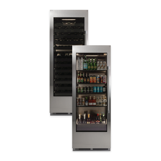
- Page 14 Column Refrigeration Installation & Operation Manual ANTI-TIP APPLICATION Anti-Tip Application for Freestanding Applications NOTE: Cabinet must be leveled before securing to wall with anti-tip bracket. New Glass door model image...
-
Page 15: Installing Door Overlay Panel
1.001 & UP: .012 4 " THIS DOCUMENT / PUBLICATION / SOFTWARE / DRAWING CONTAINS PROPRIETARY INFORMATIO FORM, ELECTRONIC OR MECHANICAL, INCLUDING PHOTOCOPYING, RECORDING, OR USED IN ANY I CORPORATION. COPYRIGHT 20 SW C:\Perlick\Engineering\Projects\Refrigeration\1601802\CAD Files\1007917.slddrw 4” Toe Kick Wood Overlay Template Glass Door... - Page 16 A custom door panel and handle hardware must be installed if a customer chooses to not purchase a Perlick stainless steel door panel. The thickness of the custom panel can vary. A minimum 5/8” (16) thick panel is required, but the thickness can be increased provided it does not exceed the maximum panel weight of 65 lbs (29).
-
Page 17: 24" Column Glass Door Template For 4"/6" Toe Kick
2 " OVERLAY 2 " 60" CUTOUT 8 " 8 " 8 " 8 " 17" CUTOUT MATE 4 " .136 .500 (2X) QTY.: 16 " 8 " FINISH 16 " TYP 8 " TYP 4 " SW C:\Perlick\Engineering\Projects\Refrigeration\1601802\CAD Files\1007917.slddrw... - Page 18 SCALE 1 : 2 8 " 8 " 17" CUTOUT MATERIAL: WOOD 8 " QTY.: 8 " 4 " FINISH: .136 .500 (2X) 16 " TYP 8 " TYP 4 " THIS DOCUMENT / PUB FORM, ELECTRONIC OR C:\Perlick\Engineering\Projects\Refrigeration\1601802\CAD Files\1007917.slddrw...
-
Page 19: 30" Column Glass Door Template For 4"/6" Toe Kick
Column Refrigeration Installation & Operation Manual 30 INCH COLUMN GLASS DOOR TEMPLATE FOR 4” TOE KICK 8 " .136 .500 (5X) 4 " 8 "(2X) 4 " FOR LOCK OPTIONAL 8 "(3X) USE DRILL FIXTURE TO 4 " LOCATE HOLE 8 "(2X) 67"(2X) 16 "... - Page 20 Column Refrigeration Installation & Operation Manual 30 INCH COLUMN GLASS DOOR TEMPLATE FOR 6” TOE KICK .136 .500 (5X) 8 " 4 " 8 "(2X) 4 " 8 "(3X) FOR LOCK OPTIONAL USE DRILL FIXTURE TO LOCATE HOLE 4 " 8 "(2X) 65"(2X) 16 "...
-
Page 21: 24" Wine Shelf Front Detail
BREAK SHARP EDGES - .015 X 45° SCALE: 1:4 THIS DOCUMENT / PUBLICATION / SOFTWARE / DRAWING CONTAINS PROPRIETARY INFORMATION WHICH IS THE PROPERTY OF THE PERLICK CORPORATION. IT MAY NOT BE REPRODUCED OR TRANSMITTED IN ANY FORM, ELECTRONIC OR MECHANICAL, Milwaukee, Wisconsin Perlick Corporation RADIUS SHARP FILLETS - .015 TO .031... -
Page 22: 30" Wine Shelf Front Detail
SCALE: 1:4 Milwaukee, Wisconsin THIS DOCUMENT / PUBLICATION / SOFTWARE / DRAWING CONTAINS PROPRIETARY INFORMATION WHICH IS THE PROPERTY OF THE PERLICK CORPORATION. IT MAY NOT BE REPRODUCED OR TRANSMITTED IN ANY FORM, ELECTRONIC OR MECHANICAL, RADIUS SHARP INCLUDING PHOTOCOPYING, RECORDING, OR USED IN ANY INFORMATION STORAGE, TRANSMISSION, OR RETRIEVAL SYSTEM, WITHOUT WRITTEN PERMISSION FROM THE PERLICK CORPORATION. COPYRIGHT 2015 PERLICK CORPORATION. ALL RIGHTS RESERVED. -
Page 23: Door Overlay Panel Adjustment
Column Refrigeration Installation & Operation Manual DOOR OVERLAY PANEL ADJUSTMENT Close the door to make adjustments to align panels and reveals. For up-and-down adjustments, turn the height adjustment screws in the top bracket in and out. DOOR Adjust the screws as needed to achieve an even reveal on each side of the door overlay. -
Page 24: Door Trim Installation
DIVIDER PANEL FRAME 1 GASKET CONDENSER DIVIDER PANEL INSTALLATION STEPS INSTALLATION STEPS INSTALL FRAME 1 TO OVERLAY. DOOR TRIM INSTALL GASKET ONTO FRAME 2. SW C:\Perlick MOUNT FRAME 2 ONTO FRAME 1. DOOR PANEL DETAIL K SCALE 1 : 4... - Page 25 Column Refrigeration Installation & Operation Manual SCREW ZONE FOR 24 AND 30 INCH OVERLAY TEMPLATES 4 " 16 " 16 " 4 " 4 " NOTE: HATCH AREAS SHOULD PROVIDE ENO THICKNESS FOR WOOD SCREW FOR OVERLAY ATTACHMENT BRACKETS. 66" 2 "...
-
Page 26: Wine Storage And Shelving
Column Refrigeration Installation & Operation Manual WINE STORAGE Wine Shelving ▪ Prior to making shelf adjustments, clear the shelf of product. Shelf must be empty prior to changing its position. To Remove Wine Shelves To Install Wine Shelves PILASTER PILASTER FIXED SLIDER WITH BRACKET FIXED SLIDER WITH BRACKET SHELF... - Page 27 Column Refrigeration Installation & Operation Manual WINE STORAGE To Remove Wine Shelf Fronts To Remove Wine Shelf Plugs ▪ Remove shelf plugs prior to the removal ▪ Use a #2 Phillips screwdriver to remove the of shelving. Use a needle nose pliers to two screws on either side of the wine shelf grab onto the rubber plug and wiggle until front as pictured.
-
Page 28: Toe Kick Installation
Column Refrigeration Installation & Operation Manual COMPLETION - TOE KICK INSTALLATION Install the toe kick by snapping into latch catches. TOE KICK CLEARANCE... -
Page 29: Air Filter Installation
Column Refrigeration Installation & Operation Manual INSTALLING AIR FILTERS Carbon Air Filter The carbon air filters should be placed on the perforated panel located in the top-rear of the cabinet. NOTE: For units with shelves the top shelf will need to be removed for filter. 1. -
Page 30: Perliq Digital Control Operation
(wine models only) Selecting a Temperature Zone Cellar temperature setting Perlick’s PerlIQ™ digital controller is preset with Temperature adjustment (up and down in recommended temperature settings for white wine, 1° increments) red wine and cellaring. Within the presets, you have the ability to adjust the temperature in 1°... - Page 31 Column Refrigeration Installation & Operation Manual COLUMN DIGITAL CONTROL OPERATION Storing White Wine Cellaring Wine Perlick wine columns are preset with expert- Perlick wine columns are preset with expert- recommended temperature settings for white recommended temperature settings for cellaring wine. To set a zone in dual zone models to this (long-term storage) wine.
- Page 32 Sabbath Mode Showroom Mode All Perlick column refrigeration models have Select Showroom mode for units that are being Sabbath mode capabilities. This allows the user to used solely for display purposes. Showroom mode interact with the unit without changing the amount of has the user interface fully functional along with the energy it is using.
-
Page 33: Stainless Steel/Surface Care
▪ Mechanical Abrasion Glass Cleaning This refers to items that will scratch stainless Perlick’s triple pane glass is designed to protect steel surfaces. Steed pads, wire brushes and cabinet contents from UV light, while displaying scrapers are prime examples. -
Page 34: Troubleshooting
Normal for the system to run more frequently Condensation is normal in high humidity ambient, Condensation forms High humidity and/or frequent if installed next to another Perlick column, ensure outside of the unit door opening proper dual-installation kit has been selected Make sure the door is closing properly. - Page 35 High and Low temperature alarms may occur L1, L2, L3, L4, L5, L6 Low temperature alarm from extended door openings or heavy loading of warm product. If alarm persists, call Perlick H1, H2, H3, H4, H5, H6 High temperature alarm Technical Service at (844) 411-8050...
-
Page 36: Column Install Checklist
Has the inside of cabinet been wiped clean of any packaging or other debris? 12. Has all of the packaging been removed from customer site? 8300 West Good Hope Road, Milwaukee, WI 53223, USA perlick.com • (800) 558-5592 © 2024 Perlick Corporation Form No. Z3006...
Need help?
Do you have a question about the CC24B-2 and is the answer not in the manual?
Questions and answers