PI H-811 User Manual
Hexapod microrobot
Hide thumbs
Also See for H-811:
- User manual (110 pages) ,
- Short instructions (8 pages) ,
- User manual (99 pages)
Table of Contents
Advertisement
Quick Links
MS235E
H-811 Hexapod Microrobot
User manual
Version: 2.5.0
Physik Instrumente (PI) GmbH & Co. KG, Auf der Roemerstrasse 1, 76228 Karlsruhe, Germany
Phone +49 721 4846-0, Fax +49 721 4846-1019, Email info@pi.ws, www.pi.ws
Date: 23.02.2023
This document describes the following products:
H-811.I2
Miniature hexapod microrobot, brushless DC
motor, 5 kg load capacity, 10 mm/s max.
velocity
H-811.I2V
Miniature hexapod microrobot, brushless DC
motor, vacuum compatible to 10
load capacity, 10 mm/s velocity
H-811.F2
Miniature hexapod microrobot for optical
alignment, removable magnetic plate,
brushless DC motor, 5 kg load capacity, 10
mm/s max. velocity
H-811.S2
Miniature hexapod microrobot for high
dynamics applications, direct drive, 1.5 kg load
capacity, 10 mm/s maximum velocity
hPa, 5 kg
-6
Advertisement
Table of Contents

Related Manuals for PI H-811


Summary of Contents for PI H-811
- Page 1 Miniature hexapod microrobot for high dynamics applications, direct drive, 1.5 kg load capacity, 10 mm/s maximum velocity Physik Instrumente (PI) GmbH & Co. KG, Auf der Roemerstrasse 1, 76228 Karlsruhe, Germany Phone +49 721 4846-0, Fax +49 721 4846-1019, Email info@pi.ws, www.pi.ws...
- Page 2 BiSS is a registered trademark of iC-Haus GmbH. © 2023 Physik Instrumente (PI) GmbH & Co. KG, Karlsruhe, Germany. The text, photographs, and drawings in this manual are protected by copyright. With regard thereto, Physik Instrumente (PI) GmbH & Co. KG retains all the rights.
-
Page 3: Table Of Contents
Contents About this Document Objective and Target Group of this User Manual ............1 Symbols and Typographic Conventions..............1 Figures ........................2 Other Applicable Documents ..................2 Downloading Manuals ....................3 Safety Intended Use ......................5 General Safety Instructions ..................5 Organizational Measures .................... - Page 4 10.3.1 H-811 Hexapod .................... 66 10.3.2 000067899 Connector Holder ..............69 10.4 Load Curves ......................69 10.5 Dynamic working range of the H-811.S2 ..............75 10.6 Pin Assignment ......................78 10.6.1 Power Supply Connector ................78 10.6.2 Data Transmission Connector ..............78...
-
Page 5: About This Document
Downloading Manuals ........................3 Objective and Target Group of this User Manual This user manual contains the information necessary for using the H-811 as intended. We assume that the user has basic knowledge of closed-loop systems, motion control concepts, and applicable safety measures. -
Page 6: Figures
For better understandability, the colors, proportions, and degree of detail in illustrations can deviate from the actual circumstances. Photographic illustrations may also differ and must not be seen as guaranteed properties. Other Applicable Documents The devices and software tools from PI mentioned in this documentation are described in separate manuals. Device/program Document Document content C-887.5xx controller... -
Page 7: Downloading Manuals
Contact our customer service department (p. 51). Downloading manuals 1. Open the website www.pi.ws. 2. Search the website for the product number (e.g., H-811). 3. Click the corresponding product to open the product detail page. 4. Click the Downloads tab. -
Page 9: Safety
The H-811 is built according to state-of-the-art technology and recognized safety standards. Improper use of the H-811 may result in personal injury and/or damage to the H-811. Use the H-811 for its intended purpose only, and only when it is in perfect condition. Read the user manual. -
Page 10: Measures For Handling Vacuum-Compatible Products
2 Safety If you give the H-811 to other users, include this user manual as well as all other relevant information provided by the manufacturer. Do the work only if the user manual is complete. Missing information due to an incomplete user manual can result in minor injury and damage to equipment. -
Page 11: Product Description
Suitable Controllers ........................16 Features and Applications The various models (p. 7) of H-811 hexapod that are offered differ with respect to the maximum velocity, and load capacity as well as suitability for use in a vacuum. The parallel-kinematic design offers the following advantages: Positioning operations in six independent axes (three translational axes, three ... -
Page 12: Product View
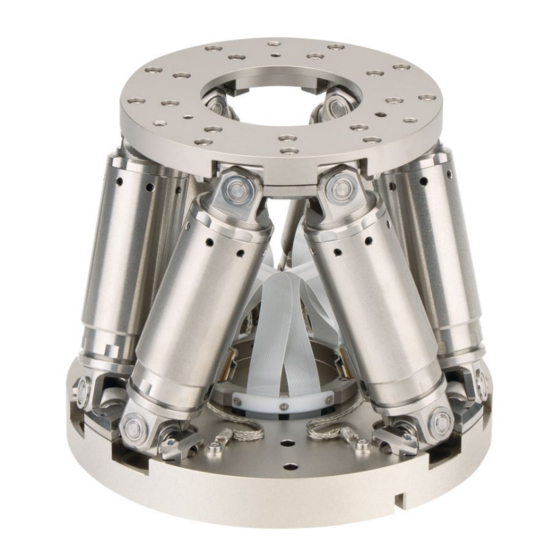
10 mm/s maximum velocity, 1.5 kg load, 0.5 m cable length. Connecting cables are not included in the scope of delivery and must be ordered separately. Product View Figure 1: Product view, H-811.F2 left, H-811.I2 right (applies to H-811.I2V and H-811.S2 also) Motion platform Strut Data transmission cable... -
Page 13: Technical Features
3.4.3 Control Der hexapod is intended for operation with a suitable controller from PI (p. 16). The controller makes it possible to command motion of individual axes, combinations of axes or all six axes at the same time in a single motion command. - Page 14 A given rotation in space is calculated from the individual rotations in the order U -> V- > W. For further information on the center of rotation, see the glossary (p. 83). Version: 2.5.0 MS235E H-811 Hexapod Microrobot...
- Page 15 The rotation around the U axis tilts the rotational axes V and W. Figure 3: Rotation around the U axis Platform in reference position Platform position: U = 10 (U parallel to spatially-fixed X axis) H-811 Hexapod Microrobot MS235E Version: 2.5.0...
- Page 16 The rotation around the V axis tilts the rotational axes U and W. Figure 4: Rotation around the V axis Platform in reference position Platform position: U = 10, V = –10 (U and V parallel to the platform level) Version: 2.5.0 MS235E H-811 Hexapod Microrobot...
-
Page 17: Id Chip
(e.g., geometry data and control parameters). The configuration data for customized hexapods is only stored on the controller if the hexapod and controller are delivered together, or if PI was correspondingly informed before delivery of the controller. -
Page 18: Scope Of Delivery
Accessory for fixing the connector holder for the data transmission cable: 2 socket head screws, M6×30 ISO 4762 1 hex key 5.0 DIN 911 Note that the cables required for connecting the H-811 to the electronics must be ordered separately. Version: 2.5.0 MS235E H-811 Hexapod Microrobot... -
Page 19: Optional Accessories
Ideal for static applications that require increased position stability. Refer to "Optional: Operating the Hexapod with a Separate 12 V Power Adapter" (p. 37) for further information. H-811.F2 model only: Mounting plate for fast replacement of different F-206.TMU assemblies H-811 Hexapod Microrobot MS235E Version: 2.5.0... -
Page 20: Suitable Controllers
Available for hexapod mechanics H-811.F2 and H-811.I2 in combination with a C-887 hexapod controller that features a high-resolution analog input. Installation is done by a PI service engineer in a remote session. Contact will be established by PI after purchase. -
Page 21: Unpacking
When handling the vacuum model of the hexapod, attention must be paid to appropriate cleanliness. At PI, all parts are cleaned before assembly. Powder-free gloves are worn during assembly and measuring. In addition, the hexapod is wipe cleaned afterwards and then shrink- wrapped twice in vacuum-compatible film. - Page 22 4. Take the foam insert together with the hexapod out of the inner box carefully. 5. Tip the foam insert with the hexapod 90° onto its longitudinal side and put it onto a surface. Version: 2.5.0 MS235E H-811 Hexapod Microrobot...
- Page 23 4 Unpacking 6. Remove the clamp from the underside of the foam insert. 7. Remove the top half of the foam insert. H-811 Hexapod Microrobot MS235E Version: 2.5.0...
- Page 24 4 Unpacking 8. Grip the base plate of the hexapod and take it out of the lower half of the foam insert. 9. Remove the foil from the hexapod. Version: 2.5.0 MS235E H-811 Hexapod Microrobot...
- Page 25 12. Compare the contents with the scope of delivery according to the contract and the delivery note. If any of the parts are wrong or are missing, contact PI immediately. 13. Inspect the hexapod for signs of damage. If there is any sign of damage, contact PI immediately.
-
Page 27: Installing
A cable break leads to failure of the hexapod. Ensure that your application fulfills the following requirements for the cables permanently installed at your hexapod: − The cables are not subject to tensile stress. − The cables are not being moved. H-811 Hexapod Microrobot MS235E Version: 2.5.0... -
Page 28: Determining The Permissible Load And Workspace
PIVeriMove, see the C887T0002 technical note (in the scope of delivery of the software). Determining the Permissible Load and Workspace Tools and Accessories PC with Windows operating system with the PI Hexapod Simulation Tool installed. For further information, see the A000T0068 technical note. -
Page 29: Grounding The Hexapod
− The cable is not subject to tensile stress. − The cable is not moved. Fix the permanently installed data transmission cable with the supplied connector holder (p. 14) to underlying surface. H-811 Hexapod Microrobot MS235E Version: 2.5.0... - Page 30 3. Fix the connector holder onto the underlying surface with the screws supplied. The free side of the connector holder is intended for the connection of a suitable data transmission cable. Refer to "Connecting the Hexapod to the Controller" (p. 30) for further information. Version: 2.5.0 MS235E H-811 Hexapod Microrobot...
-
Page 31: Mounting The Hexapod On A Surface
Put the hexapod onto the surface so that the locating pins are inserted into the corresponding locating holes in the hexapod's base plate. 3. Mount the hexapod on the three mounting holes in the base plate with the included screws. H-811 Hexapod Microrobot MS235E Version: 2.5.0... -
Page 32: Fixing The Load To The Hexapod
Only mount the hexapod and the load on the mounting fixtures (holes) intended for this purpose. INFORMATION H-811.F2 model only: The load to be aligned can be fixed to the mounting plate or directly to the motion platform. Fixing to the mounting plate is recommended. - Page 33 Optional: Two Ø 3 mm m6 locating pins for easy alignment of the load on the hexapod, not included in the scope of delivery H-811.F2 model only: If you want to fix several loads to be aligned in quick succession: one additional mounting plate each per assembly, available as optional accessory (p.
-
Page 34: Connecting The Hexapod To The Controller
(see figure). Connecting the Hexapod to the Controller Cables with a length of 0.5 m (H-811.I2., .F2, .S2) or 2 m (811.I2V) are installed permanently on the hexapod. Connecting cables are not included in the scope of delivery and must be ordered separately (p. - Page 35 If you want to operate a vacuum-compatible hexapod in a vacuum chamber: Suitable tools for installing the vacuum feedthrough If necessary: Installing vacuum feedthroughs Figure 8: Vacuum feedthrough for data transmission (4668), dimensions in mm 4 holes, Ø6 x 45° for M3 countersunk screw H-811 Hexapod Microrobot MS235E Version: 2.5.0...
- Page 36 Pay attention to the assignment specified on the labeling of the sockets, plug − connectors, and cables. − Pay attention to the mechanical coding of connectors and sockets. − Do not use force. Use the integrated screws to secure the connections against accidental − disconnection. Version: 2.5.0 MS235E H-811 Hexapod Microrobot...
- Page 37 Controller Refer to "Suitable Controllers" (p. 16) Hexapod H-811.x2 Power adapter, from the scope of delivery of the controller, 24 V DC output Data transmission cable* Power supply cable* * Must be ordered separately. H-811 Hexapod Microrobot MS235E Version: 2.5.0...
- Page 38 Vacuum chamber Data transmission cable* Power supply cable* Vacuum feedthrough for data transmission** Vacuum feedthrough for power supply** * Must be ordered separately. ** From the scope of delivery of the hexapod (p. 14) Version: 2.5.0 MS235E H-811 Hexapod Microrobot...
-
Page 39: Startup
Do not place any objects in areas where they can be caught by moving parts. Stop the motion immediately if a controller malfunction occurs. H-811 Hexapod Microrobot MS235E Version: 2.5.0... -
Page 40: Starting Up The Hexapod System
Starting up the hexapod system 1. Start up the controller (refer to the user manual of the controller). 2. Run a few motion cycles for test purposes (refer to the user manual of the controller). Version: 2.5.0 MS235E H-811 Hexapod Microrobot... -
Page 41: Optional: Operating The Hexapod With A Separate 12 V Power Adapter
Send the following commands to adapt the controller's settings permanently to the 12 V power adapter of the hexapod and to reboot the controller: SVO X 0 CCL 1 advanced SPA 1 0x19004000 0 H-811 Hexapod Microrobot MS235E Version: 2.5.0... - Page 42 4. Use PITerminal to establish communication between the controller and the PC via the TCP/IP interface or the RS-232 interface. 5. Send the following commands to adapt the controller's settings permanently to the hexapod's 24 V supply: SVO X 0 CCL 1 advanced Version: 2.5.0 MS235E H-811 Hexapod Microrobot...
- Page 43 8. If there is an M12 screw plug, remove it from the controller's 24 V output (24 V Out 7 9. Connect the hexapod to the 24 V output of the controller. For further information, see "Connecting the Hexapod to the Controller" (p. 30). H-811 Hexapod Microrobot MS235E Version: 2.5.0...
-
Page 45: Maintenance
Cleaning the Hexapod ........................42 Packing the Hexapod for Transport ..................... 42 PI offers a range of wraparound services for all their products, many of which are designed to increase the system’s lifetime and uptime: Remote system setup: An expert ensures that your system is optimized and runs ... -
Page 46: Cleaning The Hexapod
Cable break due to excessively bent or crushed cable! A cable break leads to failure of the hexapod. Pack the hexapod so that the cables are not bent or crushed too much. Accessories Original packaging (p. 14) Version: 2.5.0 MS235E H-811 Hexapod Microrobot... - Page 47 2. Pack the hexapod in electrostatic dissipative film to protect against dirt. 3. Grip the base plate of the hexapod and lay it sideways into one half of the foam insert. Make sure that the hexapod is correctly aligned to the recesses in the insert. H-811 Hexapod Microrobot MS235E Version: 2.5.0...
- Page 48 7 Maintenance 4. Align the second half of the foam insert and put it onto the hexapod. 5. Push the clamp onto the foam insert to hold both halves together. Version: 2.5.0 MS235E H-811 Hexapod Microrobot...
- Page 49 7. Put the inner box into the outer box. Make sure that it is sitting correctly on the cushioned corners. 8. Put the hexapod into the inner box: a) Set the foam insert upright so that the clamp and therefore the hexapod's base plate are pointing downwards . H-811 Hexapod Microrobot MS235E Version: 2.5.0...
- Page 50 Lower the foam insert with the hexapod into the inner box carefully. 9. Close the inner box. 10. Put four cushioned corners onto the inner box. 11. Close the outer box. 12. Secure the box on the pallet. Version: 2.5.0 MS235E H-811 Hexapod Microrobot...
-
Page 51: Troubleshooting
Z. Blocked or broken Contact our customer service department joint (p. 51). Load too big The hexapod does The mechanics is not Check the power supply cable. H-811 Hexapod Microrobot MS235E Version: 2.5.0... - Page 52 − In PIMikroMove, open the Diagnostic Information window by choosing C- 887 > Show diagnostic information... on the menu − Send the DIA? command. Meaning of the displayed information: 1 (Hexapod Powered): Version: 2.5.0 MS235E H-811 Hexapod Microrobot...
- Page 53 Send the VER? command to check the information for the hexapod type, serial number, and manufacturing date saved on the ID chip. Example for the response: IDChip: H-811.F-2 SN123456789 20/1/2016send the CST? command. The response shows the hexapod, to which the controller is adapted.
- Page 54 If the problem with your hexapod is not listed in the table or cannot be solved as described, contact our customer service department (p. 51). Version: 2.5.0 MS235E H-811 Hexapod Microrobot...
-
Page 55: Customer Service Department
9 Customer Service Department Customer Service Department For inquiries and orders, contact your PI sales engineer or send us an email (mailto:service@pi.de). If you have questions concerning your system, provide the following information: − Product and serial numbers of all products in the system Firmware version of the controller (if applicable) −... -
Page 57: Technical Data
(https://www.pi.ws). In this Chapter Specifications ..........................53 Ambient Conditions and Classifications ..................65 Dimensions ..........................66 Load Curves ..........................69 Dynamic working range of the H-811.S2 ..................75 Pin Assignment ..........................78 10.1 Specifications 10.1.1 Data Table Specifications H-811.I2 Motion H-811.I2... - Page 58 Maximum holding force, base plate in any orientation 2.5 N Maximum holding force, base plate horizontal 15 N Maximum load capacity, base plate in any orientation 2.5 kg Maximum load capacity, base plate horizontal 5 kg Overall mass 2.2 kg Version: 2.5.0 MS235E H-811 Hexapod Microrobot...
- Page 59 Maximum angular velocity in θZ, unloaded 250 mrad/s Typical velocity in X, unloaded 5 mm/s Typical velocity in Y, unloaded 5 mm/s Typical velocity in Z, unloaded 5 mm/s Typical angular velocity in θX, unloaded 120 mrad/s H-811 Hexapod Microrobot MS235E Version: 2.5.0...
- Page 60 Scanning time of spiraled area scan 500 µm Ø < 2 s typ. Drive properties H-811.F2 Tolerance Drive type Brushless DC motor Mechanical properties H-811.F2 Tolerance Stiffness in X 0.7 N/µm Stiffness in Y 0.7 N/µm Stiffness in Z 8 N/µm Version: 2.5.0 MS235E H-811 Hexapod Microrobot...
- Page 61 ± 21 ° Maximum velocity in X 10 mm/s Maximum velocity in Y 10 mm/s Maximum velocity in Z 10 mm/s Maximum angular velocity in θX 240 mrad/s Maximum angular velocity in θY 240 mrad/s H-811 Hexapod Microrobot MS235E Version: 2.5.0...
- Page 62 ± 10 µrad typ. Minimum incremental motion in X 1 µm typ. Minimum incremental motion in Y 1 µm typ. Minimum incremental motion in Z 0.5 µm typ. Minimum incremental motion in θX 12 µrad typ. Version: 2.5.0 MS235E H-811 Hexapod Microrobot...
- Page 63 25 mm supply cable Outer diameter data transmission cable 9.5 mm Minimum bending radius for fixed installation, data 95 mm transmission cable Connector for data transmission HD D-sub 78-pin (m) Recommended controllers / drivers C-887.5x H-811 Hexapod Microrobot MS235E Version: 2.5.0...
- Page 64 0/0/0. The cables fixed to the H-811.x2 are 0.5 m long respectively. The cables fixed to the H-811.x2 are not drag chain compatible.
- Page 65 Miscellaneous H-811.I2V Tolerance Connector for supply voltage LEMO Cable length Vacuum class 10⁻⁶, hPa Operating temperature range 0 to 50 °C Maximum bake out temperature 80 °C Outer diameter power supply cable 4.7 mm H-811 Hexapod Microrobot MS235E Version: 2.5.0...
- Page 66 0/0/0. The cables fixed to the H-811.I2V are not drag chain compatible. Note on outer diameter data transmission cable: The data transmission connection consists of 2 cables that end in one connector.
-
Page 67: Maximum Ratings
Data Transmission and Power Supply Cables Data transmission Power supply cable, single-side Power supply cable, straight cable angled connector connectors Alle Hexapodtypen H-820, H-824, H-825, H-840, H-850 H-810, H-811, H-206 C-815.82D02 C-815.82P02A C-815.82P02E C-815.82D03 C-815.82P03A C-815.82P03E C-815.82D05 C-815.82P05A C-815.82P05E... - Page 68 M12 m/f Power supply cable, angled connector Unit Cable length L 2 / 5 / 7.5 / 10 / 20 m Minimum bending radius in a drag chain Minimum bending radius with the fixed installation Version: 2.5.0 MS235E H-811 Hexapod Microrobot...
-
Page 69: Ambient Conditions And Classifications
Highest relative humidity of 80% at temperatures of up Humidity: to 31°C, decreasing linearly to a relative humidity of 50% at 40°C Degree of protection according IP20 to IEC 60529 Area of application For indoor use only Maximum altitude 2000 m H-811 Hexapod Microrobot MS235E Version: 2.5.0... -
Page 70: Dimensions
10.3.1 H-811 Hexapod Dimensions in mm. Note that a comma is used instead of a decimal point in the drawings. Figure 12: H-811 hexapod, .I2, .S2 models, at zero position of nominal travel range Version: 2.5.0 MS235E H-811 Hexapod Microrobot... - Page 71 10 Technical Data Figure 13: H-811 hexapod, model .I2V, at zero position of nominal travel range H-811 Hexapod Microrobot MS235E Version: 2.5.0...
- Page 72 10 Technical Data Figure 14: H-811 hexapod, .F2 model, at zero position of nominal travel range If the controller's factory settings are used for the coordinate system and the center of rotation, the hexapod in the figure corresponds to the position X=Y=Z=U=V=W=0.
-
Page 73: 000067899 Connector Holder
Dimensions in mm. Note that the decimal points are separated by a comma in the drawings. Figure 15: 000067899 connector holder for strain relief 10.4 Load Curves Figure 16: Maximum loads on the H-811.I2 when mounted horizontally H-811 Hexapod Microrobot MS235E Version: 2.5.0... - Page 74 10 Technical Data Figure 17: Maximum loads on the H-811.I2 when mounted vertically Figure 18: Maximum loads on the H-811.I2 when mounted at the most unfavorable angle Version: 2.5.0 MS235E H-811 Hexapod Microrobot...
- Page 75 10 Technical Data Figure 19: Maximum permissible force acting on the H-811.I2 when mounted horizontally Figure 20: Maximum loads on the H-811.I2V when mounted horizontally H-811 Hexapod Microrobot MS235E Version: 2.5.0...
- Page 76 10 Technical Data Figure 21: Maximum loads on the H-811.I2V when mounted vertically Figure 22: Maximum loads on the H-811.I2V when mounted at the most unfavorable angle Version: 2.5.0 MS235E H-811 Hexapod Microrobot...
- Page 77 10 Technical Data Figure 23: Maximum permissible force acting on the H-811.I2V when mounted horizontally Figure 24: Maximum loads on the H-811.F2 when mounted horizontally H-811 Hexapod Microrobot MS235E Version: 2.5.0...
- Page 78 10 Technical Data Figure 25: Maximum loads on the H-811.F2 when mounted vertically Figure 26: Maximum loads on the H-811.F2 when mounted at the most unfavorable angle Version: 2.5.0 MS235E H-811 Hexapod Microrobot...
-
Page 79: Dynamic Working Range Of The H-811.S2
Figure 27: Maximum permissible force acting on the H-811.F2 when mounted horizontally 10.5 Dynamic working range of the H-811.S2 The diagrams mark the dynamic working range of the H-811.S2. Here, the following prerequisites apply: 1. A compact load is mounted centrically. - Page 80 10 Technical Data Equation 1: Dynamic working range of the H-811.S2, X and Y, 2.5 kg Equation 2: Dynamic working range of the H-811.S2, Z, 2.5 kg Version: 2.5.0 MS235E H-811 Hexapod Microrobot...
- Page 81 10 Technical Data Equation 3: Dynamic working range of the H-811.S2, U and V, 2.5 kg Equation 4: Dynamic working range of the H-811.S2, W, 2.5 kg H-811 Hexapod Microrobot MS235E Version: 2.5.0...
-
Page 82: Pin Assignment
Data Transmission Connector Data transmission between hexapod and controller HD D-sub 78 panel plug Function All signals: TTL Pin Assignment Signal Signal CH1 Sign IN CH1 MAGN IN CH1 Ref OUT CH1 LimP OUT Version: 2.5.0 MS235E H-811 Hexapod Microrobot... - Page 83 CH5 B+ OUT CH5 A- OUT CH5 B- OUT CH6 Sign IN CH6 MAGN IN CH6 Ref OUT CH6 LimP OUT CH6 LimN OUT CH6 A+ OUT CH6 B+ OUT CH6 A- OUT CH6 B- OUT H-811 Hexapod Microrobot MS235E Version: 2.5.0...
- Page 84 10 Technical Data Signal Signal ID Chip Brake/Enable drive Power Good 24 V 24 V input output Version: 2.5.0 MS235E H-811 Hexapod Microrobot...
-
Page 85: Old Equipment Disposal
Dispose of your old equipment according to international, national, and local rules and regulations. To fulfill the responsibility as the product manufacturer, Physik Instrumente (PI) GmbH & Co. KG undertakes environmentally correct disposal of all old PI equipment made available on the market after 13 August 2005 without charge. -
Page 87: Glossary
The intersection of the axes X, Y, and Z of the spatially fixed Cartesian coordinate system (0,0,0) is referred to as the origin. The Z axis is perpendicular to the base plate of the hexapod. H-811 Hexapod Microrobot MS235E Version: 2.5.0... - Page 88 12 Glossary The following example figures of the H-810 hexapod show that the coordinate system does not move along with motion of the platform. Figure 28: H-810 hexapod in the reference position. Cable exit Version: 2.5.0 MS235E H-811 Hexapod Microrobot...
- Page 89 12 Glossary Figure 29: H-810 hexapod, the platform of which has been moved in X. Cable exit H-811 Hexapod Microrobot MS235E Version: 2.5.0...
-
Page 91: Appendix
The following test cycles are performed: Motion over the entire travel range with at least 20 measuring points, in at least five cycles. Motion over partial sections, e.g., ±1 mm in increments of for example, 100 µm H-811 Hexapod Microrobot MS235E Version: 2.5.0... -
Page 93: European Declarations Of Conformity
13 Appendix 13.2 European Declarations of Conformity For the H-811, declarations of conformity were issued according to the following European statutory requirements: EMC Directive RoHS Directive The standards applied for certifying conformity are listed below. EMC: EN 61326-1 Safety: EN 61010-1...
Need help?
Do you have a question about the H-811 and is the answer not in the manual?
Questions and answers