Table of Contents
Advertisement
Quick Links
MP134E
Q-522 Miniature Stage
User Manual
Version: 1.0.1
Date: 23.08.2019
This document describes the following
products:
Q-522.xyz
Q-Motion Miniature Linear Stage,
Piezoelectric Inertia Drive
x: Travel range
0 = 6.5 mm
1 = 13 mm
2 = 26 mm
y: Equipment with a sensor
0 = without sensor
3 = with sensor, sensor resolution 4 nm
4 = with sensor, sensor resolution 1 nm
z: Suitable for vacuum
0 = suitable to 0.1 hPa
U = suitable to 10
Physik Instrumente (PI) GmbH & Co. KG, Auf der Roemerstr. 1, 76228 Karlsruhe, Germany
Phone: +49 721 4846-0, Fax: +49 721 4846-1019, E-mail: info@pi.ws
-9
hPa
Advertisement
Table of Contents

Related Manuals for PI Q-Motion Q-522


Summary of Contents for PI Q-Motion Q-522
- Page 1 4 = with sensor, sensor resolution 1 nm z: Suitable for vacuum 0 = suitable to 0.1 hPa U = suitable to 10 Physik Instrumente (PI) GmbH & Co. KG, Auf der Roemerstr. 1, 76228 Karlsruhe, Germany Phone: +49 721 4846-0, Fax: +49 721 4846-1019, E-mail: info@pi.ws...
- Page 2 With regard thereto, Physik Instrumente (PI) GmbH & Co. KG retains all the rights. Use of said text, photographs and drawings is permitted only in part and only upon citation of the source.
-
Page 3: Table Of Contents
Contents About this Document Goal and Target Audience of this User Manual ........... 1 Symbols and Typographic Conventions ............... 1 Definition ....................... 2 Figures ........................2 Other Applicable Documents ................3 Downloading Manuals ..................3 Safety Intended Use ......................5 General Safety Instructions .................. - Page 4 Startup and Operation General Notes on Startup and Operation ............33 Starting Up the Stage ..................36 6.2.1 Starting Up the Q-522.x0z with the E-870 Drive Electronics ....37 6.2.2 Starting Up the Q-522.x4z with the E-871 Controller .......39 Maintenance General Notes on Maintenance ................41 Performing a Maintenance Run ................41 Cleaning the Q-522 ....................41 Troubleshooting...
-
Page 5: About This Document
1 About this Document About this Document In this Chapter Goal and Target Audience of this User Manual ............1 Symbols and Typographic Conventions ................ 1 Definition ........................2 Figures ........................... 2 Other Applicable Documents ..................3 Downloading Manuals ....................3 1.1 Goal and Target Audience of this User Manual This manual contains information on the intended use of the Q-522. -
Page 6: Definition
1 About this Document INFORMATION Information for easier handling, tricks, tips, etc. Symbol/Label Meaning Action consisting of several steps whose sequential order must be observed Action consisting of one or several steps whose sequential order is irrelevant List item p. -
Page 7: Other Applicable Documents
CD), access to the manuals is password-protected. The password is stored on the CD. Availability of the manuals: Password-protected manuals: FTP download directory Freely available manuals: PI website Follow the corresponding instructions for downloading. Q-522 Miniature Stage MP134E Version: 1.0.1... - Page 8 4. Find the user name and the password in the section "User login for software download" in the Release News. 5. Open the FTP download directory (ftp://pi-ftp.ws). − Windows operating systems: Open the FTP download directory in Windows Explorer.
-
Page 9: Safety
2 Safety Safety In this Chapter Intended Use ......................... 5 General Safety Instructions ................... 5 Organizational Measures ....................6 Measures for Handling Vacuum-Compatible Products ..........6 2.1 Intended Use The Q-522 is a laboratory device as defined by DIN EN 61010-1. It is intended to be used in interior spaces and in an environment which is free of dirt, oil, and lubricants. -
Page 10: Organizational Measures
2.4 Measures for Handling Vacuum-Compatible Products When handling the vacuum version of the stage, attention must be paid to appropriate cleanliness. At PI, all parts are cleaned before assembly. During assembly and measurement, powder-free gloves are worn. Afterwards, the stage is cleaned once again by wiping and shrink-wrapped twice in vacuum-compatible film. -
Page 11: Product Description
3 Product Description Product Description In this Chapter Model Overview ......................7 Product View ....................... 10 Product Labeling ......................12 Scope of Delivery ......................13 Accessories ......................... 13 Suitable Electronics ..................... 14 Technical Features ...................... 15 3.1 Model Overview Classification of the Q-522 models Fifteen standard versions of the Q-522 stage are available. - Page 12 3 Product Description Vacuum Travel Linear encoder Model Dimensions suitability (to range present hPa) Q-522.240 26 mm 32 mm × 42 mm × 10 mm Yes (1 nm) Q-522.00U 6.5 mm 22 mm × 22 mm × 10 mm Q-522.04U 6.5 mm 32 mm ×...
- Page 13 3 Product Description Order Product name number Q-522.230 Q-Motion Miniature Linear Stage, 26 mm Travel Range, Linear Encoder, 4 nm Resolution, 0.6 N Drive Force, Dimensions 22 × 33 × 10 mm (W × L × H), Piezoelectric Inertia Drive Q-522.240 Q-Motion Miniature Linear Stage, 26 mm Travel Range, Linear Encoder, 1 nm Resolution, 0.6 N Drive Force, Dimensions 22 ×...
-
Page 14: Product View
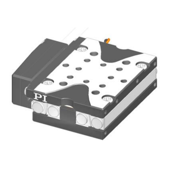
3 Product Description 3.2 Product View Figure 1: Example of model without linear encoder: Q-522.100 stage Moving platform Ceramic rail of the drive Base body Linear guiding Cable exit for drive connection Figure 2: Example of model with linear encoder: Q-522.140 stage Case of the linear encoder Ruler of the linear encoder Moving platform... - Page 15 3 Product Description Figure 3: Example: Stage which is not suitable for operation in a vacuum, equipped with sensor Only with vacuum-incompatible models with sensor: ESD protective cap Connection for drive and sensor; with vacuum-incompatible models: Sub-D 15 (m) connector, with vacuum-compatible models: Sub-D 15 (f) connector With vacuum-incompatible models with sensor: Warning sign "Electrostatic sensitive devices"...
-
Page 16: Product Labeling
3 Product Description 3.3 Product Labeling Figure 5: Type plate of the Q-522: Position of the product labeling (example view) Figure 6: Q-522: Position of the product labeling (example view) Position Labeling Description 113064246 Serial number (example), individual for each Q-522 Meaning of the places (counting from left): 1 = internal information, 2 and 3 = manufacturing year,... -
Page 17: Scope Of Delivery
3 Product Description Position Labeling Description A, B CE conformity mark WWW.PIMICOS.COM Manufacturer's address (website) A, C Manufacturer's logo Symbol for the protective earth conductor, marks the protective earth connection of the Q-522 3.4 Scope of Delivery The Q-522 is delivered with the following components: Item ID Components Q-522... -
Page 18: Suitable Electronics
3 Product Description 3.6 Suitable Electronics Electronics Suitable for Order number Description Stage without Stage with sensor sensor Q-522.x00 Q-522.x40 Q-522.x0U Q-522.x4U E-870.10 PIShift Piezomotor / PiezoMike Drive Electronics, 1 Channel, OEM Board E-870.11 PIShift Piezomotor / PiezoMike Drive Electronics, 1 Channel, ... -
Page 19: Technical Features
Settings for the sensor: Interpolation rate, corrections of hysteresis as well as of phase and offset, gain values When switched on or rebooted, controllers from PI read the data from the ID chip. For more information on the ID chip recognition, see the manual of the controller used. -
Page 21: Unpacking
INFORMATION When handling the vacuum version of the stage, attention must be paid to appropriate cleanliness. At PI, all parts are cleaned before assembly. During assembly and measurement, powder-free gloves are worn. Afterwards, the stage is cleaned once again by wiping and shrink-wrapped twice in vacuum-compatible film. -
Page 23: Installation
5 Installation Installation In this Chapter General Notes on Installation ..................19 Mounting the Q-522 on a Surface and Connecting It to a Protective Earth Conductor ............................. 21 Setting Up a Multi-Axis System ................... 24 Affixing the Load to the Q-522 ..................26 Connecting the Q-522 to the Electronics .............. - Page 24 5 Installation NOTICE Malfunction due to soiling! Any type of soiling, e.g. dust, oil, lubricant or condensation, will render the Q-522 inoperable. Keep the Q-522 free from dirt and condensation. Avoid touching the ceramic rail of the drive and the ruler of the linear encoder. NOTICE Electrostatic hazard The Q-522.x40 models (sensor present;...
-
Page 25: Mounting The Q-522 On A Surface And Connecting It To A Protective Earth Conductor
NOTICE Damage from unsuitable cables! Unsuitable cables can damage the electronics. Only use cables provided by PI for connecting the Q-522 to the electronics. INFORMATION For the reproducibility of the positioning to be optimal, all components must be affixed with zero-backlash. - Page 26 5 Installation NOTICE Warping of the Q-522 due to mounting on uneven surfaces! Mounting the Q-522 on an uneven surface can warp the Q-522. Warping reduces the accuracy. Mount the Q-522 on an even surface. The recommended evenness of the surface is ≤2 µm.
- Page 27 5 Installation Prerequisites You have read and understood the general notes on installation (p. 19). The Q-522 is disconnected from the electronics. You have provided a suitable surface (for the required position and depth of the holes for accommodating the screws and locating pins, see "Dimensions" (p.
-
Page 28: Setting Up A Multi-Axis System
5 Installation b) Introduce the screw into the counter-sunk hole. Tighten the screw with a maximum torque of 35 Ncm. d) Make sure that the screw head does not protrude from the counter-sunk hole. e) Repeat the steps a) to d) for the other counter-sunk hole in the base body of the Q-522. - Page 29 5 Installation Figure 9: Example: Affixing a Q-522.04z on a Q-522.04z Prerequisites You have read and understood the general notes on installation (p. 19). The stages are disconnected from the electronics. You have properly mounted the lower stage on a surface and connected it to a protective earth conductor (p.
-
Page 30: Affixing The Load To The Q-522
5 Installation Setting up a multi-axis system 1. Insert the two locating pins into the locating holes on the bottom side of the upper Q-522 or in the moving platform of the lower Q-522 (see figures above). 2. Place the upper Q-522 on the lower Q-522 so that the locating pins are inserted into the corresponding locating holes on the other side. - Page 31 5 Installation Figure 10: Q-522.00z Figure 11: Q-522.10z Figure 12: Q-522.20z The arrows identify the following mounting holes in the moving platform of the Q-522: For load alignment: Black arrows: Locating holes Ø 1.5 mm H7, depth 2 mm For affixing the load: White arrows: M1.6 threaded holes, depth 2.5 mm Light-gray arrows:...
- Page 32 5 Installation Prerequisites You have read and understood the general notes on installation (p. 19). You have properly mounted the stage on a surface (p. 21) or on a Q-522 (p. 24). The stage is disconnected from the electronics. ...
-
Page 33: Connecting The Q-522 To The Electronics
5 Installation 5.5 Connecting the Q-522 to the Electronics The presence of a sensor defines the electronics to be used to operate the Q-522 (see also "Suitable Electronics" (p. 14)): Models without sensor (Q-522.x0z): E-870 drive electronics (p. 29) ... -
Page 34: Connecting The Q-522 To The Controller
5 Installation Connecting the Q-522.x00 to E-870 drive electronics with a Mini-DIN 4 socket 1. Connect the Q-522.x00 with the adapter cable: − Connect the Sub-D 15 (m) connector of the Q-522 with the connector of the adapter cable (Sub-D 15 (f)). 2. - Page 35 5 Installation Connect the Q-522.x40 to the E-871 controller 1. Connect the Q-522.x40 with the Y adapter cable: a) Remove the ESD protective cap from the Sub-D 15 (m) connector of the Q-522. b) Connect the Sub-D 15 (m) connector of the Q-522 with the connector of the Y adapter cable (Sub-D 15 (f)).
-
Page 37: Startup And Operation
6 Startup and Operation Startup and Operation In this Chapter General Notes on Startup and Operation ..............33 Starting Up the Stage ....................36 6.1 General Notes on Startup and Operation CAUTION Risk of electric shock if the protective earth conductor is not connected! If a protective earth conductor is not or not properly connected, dangerous touch voltages can occur on the Q-522 in the case of malfunction or failure of the system. - Page 38 An operating frequency that is too high can cause damage to the Q-522. Only operate the Q-522 with controllers/drivers and original accessories from PI. Do not exceed the operating frequency range (p. 49) for which the Q-522 is specified.
- Page 39 Operating voltages that are too high or incorrectly connected can cause damage to the Q-522. Only operate the Q-522 with controllers/drivers and original accessories from PI. Do not exceed the operating voltage range (p. 49) for which the Q-522 is specified.
-
Page 40: Starting Up The Stage
6 Startup and Operation NOTICE Destruction of the piezo actuators by electric flashovers! Using the Q-522 in environments that increase the electrical conductivity can lead to the destruction of the piezo actuators of the drive by electric flashovers. Electric flashovers can be caused by moisture, high humidity, liquids and conductive materials (e.g. -
Page 41: Starting Up The Q-522.X0Z With The E-870 Drive Electronics
6 Startup and Operation INFORMATION The PIShift drive develops noises in step mode. The noise development depends on the current step frequency. 6.2.1 Starting Up the Q-522.x0z with the E-870 Drive Electronics INFORMATION The values for the parameters of the E-870 drive electronics are listed in a table in this section (p. - Page 42 6 Startup and Operation The following table lists the settings for the parameters of the E-870 drive electronics. Further information on the parameter settings is found in the "Operating Time" section (p. 50). Parameter Parameter in E-870 Drive Electronics Value Unit Operating voltage, PIShift Upper Supply Voltage...
-
Page 43: Starting Up The Q-522.X4Z With The E-871 Controller
PIMicosStages2.dat stage database. The entries in the stage database are updated regularly. Download the PI Update Finder from the PI website (http://www.update.pi- portal.ws) and use it to update the PIMicosStages2.dat stage database on your For further information, see the user manual of the E-871 controller. - Page 44 6 Startup and Operation 2. If necessary: Adapt the Maximum Motor Output (ID 0x9) parameter to your application (also refer to "General Notes on Start-Up and Operation" (p. 33) and "Operating Time" (p. 50)). The E-871 user manual describes the start-up using the PIMikroMove program.
-
Page 45: Maintenance
7 Maintenance Maintenance In this Chapter General Notes on Maintenance ................... 41 Performing a Maintenance Run ................... 41 Cleaning the Q-522 ..................... 41 7.1 General Notes on Maintenance NOTICE Damage due to improper maintenance! Improper maintenance can lead to misalignment and failure of the Q-522. ... -
Page 47: Troubleshooting
8 Troubleshooting Troubleshooting Problem Possible Causes Solution Functional E-870 drive electronics from PI: Drive electronics or impairment controller has been Adapt the parameters of the drive electronics in the E-870 after system Control PC program to the Q-522 (see "Starting Up the... - Page 48 8 Troubleshooting Problem Possible Causes Solution Drive is blocked Carefully release the blockage by manually moving the moving platform back and forth. Contact our customer service department (p. 45). If the problem that occurred with your system is not listed in the table above or cannot be solved as described, contact our customer service department (p.
-
Page 49: Customer Service
9 Customer Service Customer Service For inquiries and orders, contact your PI sales engineer or send us an e-mail (info@pi.ws). If you have questions concerning your system, have the following information ready: Product codes and serial numbers of all products in the system ... -
Page 51: Technical Data
10 Technical Data 10 Technical Data In this Chapter Specifications ......................47 Operating Time ......................50 Dimensions ........................51 Pin Assignment ......................57 10.1 Specifications 10.1.1 Data Table Motion and Q-522.030 Q-522.040/ Q-522.130 Q-522.140/ Q-522.230 Q-522.240/ Q-522.x00/ Unit positioning Q-522.04U Q-522.14U Q-522.24U Q-522.x0U... - Page 52 10 Technical Data Mechanical Q-522.030 Q-522.040/ Q-522.130 Q-522.140/ Q-522.230 Q-522.240/ Q-522.x00/ Unit properties Q-522.04U Q-522.14U Q-522.24U Q-522.x0U Max. load capacity, horizontal Max. load 0.06 0.06 0.06 0.06 0.06 0.06 0.06 capacity, any Length 22 to 42 Width Height Drive Q-522.030 Q-522.040/ Q-522.130 Q-522.140/...
-
Page 53: Maximum Ratings
10 Technical Data 10.1.2 Maximum Ratings The Q-522 stage is designed for the following operating data: Maximum Operating Maximum Operating Maximum Power Voltage Frequency Consumption 48 V 20 kHz 10 W 10.1.3 Ambient Conditions and Classifications The following ambient conditions and classifications must be observed for the Q-522: Area of application For indoor use only Maximum altitude... -
Page 54: Operating Time
10 Technical Data 10.2 Operating Time The operating time and the operating frequency in step mode affect the lifetime of the stage. In order to prevent overheating and high wear, the operating time with given operating frequency and 100 % duty cycle should not exceed the values given in the following table. -
Page 55: Dimensions
10 Technical Data 10.3 Dimensions 10.3.1 Q-522.00z Dimensions in mm Signs that are used to separate decimal places: Depth and diameter of holes: Point All other dimensions: Comma Figure 13: Q-522.00z Q-522 Miniature Stage MP134E Version: 1.0.1... -
Page 56: Q-522.0Yz
10 Technical Data 10.3.2 Q-522.0yz Dimensions in mm. The dimensions of the Q-522.030 and Q-522.040 models are identical. Signs that are used to separate decimal places: Depth and diameter of holes: Point All other dimensions: Comma Figure 14: Q-522.04z Version: 1.0.1 MP134E Q-522 Miniature Stage... - Page 57 10 Technical Data 10.3.3 Q-522.10z Dimensions in mm Signs that are used to separate decimal places: Depth and diameter of holes: Point All other dimensions: Comma Figure 15: Q-522.10z Q-522 Miniature Stage MP134E Version: 1.0.1...
-
Page 58: Q-522.1Yz
10 Technical Data 10.3.4 Q-522.1yz Dimensions in mm. The dimensions of the Q-522.130 and Q-522.140 models are identical. Signs that are used to separate decimal places: Depth and diameter of holes: Point All other dimensions: Comma Figure 16: Q-522.14z Version: 1.0.1 MP134E Q-522 Miniature Stage... - Page 59 10 Technical Data 10.3.5 Q-522.20z Dimensions in mm Signs that are used to separate decimal places: Depth and diameter of holes: Point All other dimensions: Comma Figure 17: Q-522.20z Q-522 Miniature Stage MP134E Version: 1.0.1...
-
Page 60: Q-522.2Yz
10 Technical Data 10.3.6 Q-522.2yz Dimensions in mm. The dimensions of the Q-522.230 and Q-522.240 models are identical. Signs that are used to separate decimal places: Depth and diameter of holes: Point All other dimensions: Comma Figure 18: Q-522.2yz Version: 1.0.1 MP134E Q-522 Miniature Stage... -
Page 61: Pin Assignment
10 Technical Data 10.4 Pin Assignment 10.4.1 Q-522.xy0 (Vacuum-Incompatible) Connector: Sub-D 15 (m) The Sub-D 15 (m) connector transmits the signals of the drive and, for the models with sensor, in addition the signals of the sensor and of the ID chip. Figure 19: Sub-D 15 (m) connector Signal Function... -
Page 62: Q-522.Xyu (Vacuum-Compatible)
10 Technical Data 10.4.2 Q-522.xyU (Vacuum-Compatible) Connector: Sub-D 15 (f) The Sub-D 15 (f) connector transmits the signals of the drive and, for the models with sensor, in addition the signals of the sensor and of the ID chip. Figure 20: Sub-D 15 (f) connector Signal Function Direction... -
Page 63: Old Equipment Disposal
Instrumente (PI) GmbH & Co. KG ensures environmentally correct disposal of old PI equipment that was first put into circulation after 13 August 2005, free of charge. If you have old PI equipment, you can send it postage-free to the following address: Physik Instrumente (PI) GmbH & Co. KG Auf der Römerstr. - Page 65 12 EC Declaration of Conformity 12 EC Declaration of Conformity For the Q-522, an EC Declaration of Conformity has been issued in accordance with the following European directives: 2006/95/EC, Low Voltage Directive 2004/108/EC, EMC Directive 2011/65/EU, RoHS Directive The applied standards certifying the conformity are listed below. Safety (Low Voltage Directive): EN 61010-1:2010 EMC: EN 61326-1:2013 RoHS: EN 50581:2012...
Need help?
Do you have a question about the Q-Motion Q-522 and is the answer not in the manual?
Questions and answers