Advertisement
Advertisement
Table of Contents

Related Manuals for Showven uFlamer X-Gasboom


Summary of Contents for Showven uFlamer X-Gasboom
- Page 1 USER MANUAL uFlamer X-Gasboom V1.2 2024/06/15 SHOWVEN Technologies Co., Ltd...
-
Page 3: Safety Instructions
Thanks for choosing SHOWVEN uFlamer X-Gasboom, we wish it will bring you lots of exciting moments. Please read the following user’s manual and related product installation guide carefully before operating this system. Safety Instructions Δ 1. Safety icons explanation Safety instructions warn of hazards when handling equipment and provide information on how to avoid those hazards. -
Page 4: Technical Specifications
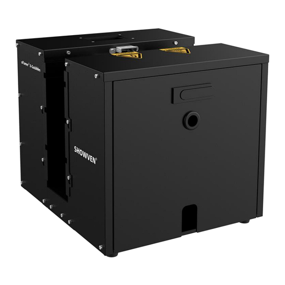
Technical Specifications Δ Model: uFlamer X-Gasboom Housing Material: 304 stainless steel Dimension: 400 360 350mm Weight: 20kg... - Page 5 Structure Δ 1. Hot surface warning icon 2. High voltage warning icon 3. Fire box 4. Handle 5. Rear panel 6. Safety loop 7. Flame detector 8. Igniter (dual) 9. Angle limit block bar (dual) 10. Cartridge holder 11. Side panel 12.
- Page 6 Diagram of bottom panel...
-
Page 7: Rear Panel
Rear Panel Δ 1. LCD Screen 2. Power Switch (with Power indicator light) 3. 3-pin XLR IN/OUT 4. 9-60V pyro signal port 5. Power IN 6. Safety Lock Button (with safety mode indicator light) 7. ARM indicator light 8. 5-pin XLR IN/OUT (5-PIN XLR IN can charge for wireless DMX pen through pin1 and 4, pin4 with DC5V power supply) 9. - Page 8 2. Button functions MENU: Switch interface to setup parameter; +: Parameter Up -: Parameter Down ENTER: Confirm and save parameters (screen will flash once when parameters saved) Note: screen display will switch to main interface if there is no operation in 10s. 3.
- Page 9 Second Line: Alert or error message alternatively display. 7. Alert Message Alert Message Why it appears How to remove Safety Switch at TEST MODE Switch to USER MODE E0 Test Mode Factory mode Switch to Normal mode E0 Factory Mode Ext Ignite ON Set Ext Ignite to OFF E0 ExtIgnite ON...
- Page 10 Preset sequence triggered by pyro signal. If set 83, Set Ext Sequence 1~83 trigger duration is the firing duration When CH1 = 0, Nozzle will back to 0 position Head to middle ON/OFF after firing Invert ON/OFF When turned on, all angles will be mirrored. When ON, nozzle motor disabled, adjust nozzle Motor Disabled ON/OFF...
-
Page 11: Firing Angles
Firing Angles: Δ The firing angle for uFlamer X-Gasboom is from -90° to 90° , from the Audience Side view, there are altogether 7 firing positions as below. Preset Firing Sequences Δ uFlamer X-Gasboom has 83 preset sequences, operator use related channel 5 DMX value or sequence No. - Page 12 SHORT flame Step sequence SHORT flame Step sequence SHORT flame Step sequence SHORT flame Step sequence SHORT flame Step sequence SHORT flame Step sequence SHORT flame Step sequence SHORT flame Step sequence SHORT flame Step sequence SHORT flame Step sequence SHORT flame Step sequence SHORT flame Step sequence SHORT flame Step sequence...
- Page 13 1. The first channel controls the firing angle when manual firing. It defines to which angle the nozzle of uFlamer X-Gasboom move to. The angle can be chosen anywhere between -90° to +90° (DMX value 0 to 255). It defines the firing nozzle stop position when use preset firing sequence.
-
Page 14: Operation
Firing Status Firing OFF Firing ON The third channel activates the actual Firing. If the DMX value of this channel higher than 253, the uFlamer X-Gasboom will firing. Channel 4 (CH4): Firing Duration setup CH4: Manual Firing Duration setup DMX Value ……... - Page 15 The E-Stop interface is power cut-off interface, and the device can be powered on normally only after the interface is connected. E-Stop terminator (standard configuration, SFMET1107). Put the E-Stop terminal in the E-Stop IN interface. E-Stopper (optional, FPEST001). E-Stopper connects with single unit of uFlamer X-Gasboom as below.
- Page 16 E-Stopper connects with multi units of uFlamer X-Gasboom in daisy chain as below: NOTICE: E-Stopper can connect 24 units of uFlamer X-Gasboom in series maximum. NOTICE: For more information about E-Stopper please check the E-Stopper manual.
- Page 17 1.4 Safety Distance Safety distance for uFlamer X-Gasboom divided into two parts safety radius around machine (a) and safety distance at firing direction (b). No person and flammable materials are allowed to stay inside the safety isolation zone when flamer was armed.
- Page 18 Safety Distance a (m) Safety Distance b (m) 2. Battery for uFlamer X-Gasboom uFlamer Gasboom can be powered through 8 pcs of 18650 cells. New X-Gasboom come only with battery compartment, customer need to get 18650 cells locally. The battery we suggest to use is with...
- Page 19 c) Pull out the cartridge holder through the hole at the bottom of machine. The cartridge holder and machine are connected with quick coupler as below, pull out the quick coupler connection to disassemble the cartridge holder. d) Screw the gas cartridge to cartridge holder tightly. e) Install cartridge holder with gas cartridge back to the machine, open the shut-off valve by rotate the knob anti-clockwise to the end position.
- Page 20 4. Install uFlamer X-Gasboom a) Horizontal installation is preferred for uFlamer X-Gasboom. If use built in gas cartridges, Gasboom with maximum tilt angle of 45° or -45° , and it can be angled to two directions as show in below...
- Page 21 If control by DMX controller, follow below steps: a) Connect a DMX cable to the DMX IN socket of first unit of uFlamer X-Gasboom, another head of this DMX cable connect to DMX console (such as FXcommander). Make sure the DMX console is powered off.
- Page 22 6. Power ON the DMX console/Pyro controller and programming Power on DMX console and program the uFlamer X-Gasboom effect on DMX console 7. Test the ignition function of uFlamer X-Gasboom Test the ignition function of machine, we can check whether the igniters of each unit of machine is working fine.
- Page 23 DANGER: Do NOT use parts or components which are not originally from SHOWVEN. NOTICE: When the device is placed or transported without packaging, please use adhesive tape to cover the nozzle to prevent foreign matter from entering. Fuel Consumption Below testing result is based on two 450g gas cartridges as show in above picture, and firing duration is 0.2s, environment temperature is 30 .
-
Page 24: Maintenance
Maintenance Δ 1. To maintain the machine in good performance and running status, it is recommended to running the device at least once per month. 2. Check the ignition probes both before and after each show, if there is any foreign objects on it please clean it up. - Page 25 Optional Parts for uFlamer Gasboom Δ Part. No. Description pcs / unit RMWAS070 G1 O ring 13.2*1.8 RMWAS065 G1 O ring 5.15*1.8 RMBOT036 Safety ring Wireless receiver ( for wireless control with RMEMD062 FXcommander) SFSMA012 Nozzle G20 SFSMA011 Nozzle G16 SFSMA013 Nozzle G25 SFSMA015...
-
Page 26: Warranty Instructions
Damage caused by external reasons (lightning strike, power supply etc.) Damage caused by improper installation or use; For product damage not included in warranty range, we can provide paid service. Invoice is necessary when applying for maintenance service from SHOWVEN... - Page 28 Showven Technologies Co., Ltd. Tel: +86-731-83833068 Web: www.showven.cn E-mail: info@showven.cn Add: No.1 Tengda Road, Liuyang Economic & Technical Development Zone, Changsha, Hunan, 410300, P.R.China...
Need help?
Do you have a question about the uFlamer X-Gasboom and is the answer not in the manual?
Questions and answers