Table of Contents
Advertisement
Quick Links
Advertisement
Table of Contents

Related Manuals for Showven uFlamer Gasboom


Summary of Contents for Showven uFlamer Gasboom
- Page 1 USER MANUAL uFlamer Gasboom V1.0 2023/05/18 SHOWVEN Technologies Co., Ltd...
-
Page 2: Safety Instructions
Thanks for choosing SHOWVEN Flame system, we wish it will bring you lots of exciting moments. Please read the following user’s manual and related product installation guide carefully before operating this system. Safety Instructions Δ 1. Safety icons explanation Safety instructions warn of hazards when handling equipment and provide information on how to avoid those hazards. -
Page 3: Technical Specifications
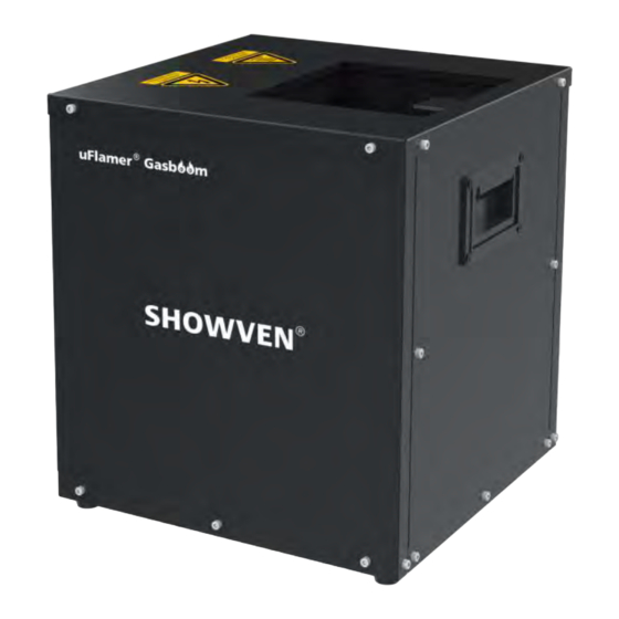
Technical Specifications Δ Model: uFlamer Gasboom Housing Material: 304 stainless steel Dimension: 320 310 325mm Weight: 13kg... - Page 4 Structure Δ 1. Top panel 2. Igniter (dual) 3. Flame detector 4. Fire box 5. Hot surface icon 6. High voltage icon 7. Rear panel 8. Cartridge holder 9. Safety loop 10. Side panel 11. Battery box 12. Audio bracket fixing hole Cartridge holder for 2 (SFMET1063) support cartridge with outer diameter is less than or equal to φ110mm, and the height is less than 275mm.
- Page 5 Diagram of bottom panel...
-
Page 6: Rear Panel
Rear Panel Δ 1. LCD Screen 2. Power Switch (with Power indicator light) 3. 3-pin XLR IN/OUT 4. 9-60V pyro signal port 5. Power IN 6. Safety Lock Button (with safety mode indicator light) 7. ARM indicator light 8. 5-pin XLR IN/OUT (5-PIN XLR IN can charge for wireless DMX pen through pin1 and 4, pin4 with DC5V power supply) 9. - Page 7 2. Button functions MENU: Switch interface to setup parameter; +: Parameter Up -: Parameter Down ENTER: Confirm and save parameters (screen will flash once when parameters saved) Note: screen display will switch to main interface if there is no operation in 10s. 3.
- Page 8 Second Line: 2-1: display SFT value under SFT mode, display “SFT:- -“ in standard mode. 2-2: DMX channel mode (2CH-P, 6CH, 2CH-N), besides, it may also display alert or error message alternatively. 7. Alert Message Alert Message Why it appears How to remove Safety Switch at TEST Switch to USER MODE...
-
Page 9: 语言 (Language)
Gasboom with 3 different channel mode: 2CH-P, 2CH-N and 6CH. 2CH-P: In this channel mode uFlamer Gasboom occupies 1 functional channel CH-F and 1 separate safety channel CH-S (this channel is independent from operational channel, can be shared with other machine). -
Page 10: Operation
0~239: Firing Disable (Emergency STOP) CH-2 Firing Enable / Disable 240~255: Firing Enable 6CH: In this channel mode uFlamer Gasboom occupies 6 functional channel. This channel mode is designed to control the uFlamer together with CIRCLE FLAMER on our Host Controller. Channel Function Value... - Page 11 NOTICE: The yellow area is E-Stop interface. The device enabled only when there is E-Stop terminal or E-Stopper connected the E- stop IN interface. 1.3 E-Stop The E-Stop interface is power cut-off interface, and the device can be powered on normally only after the interface is connected.
- Page 12 NOTICE: For more information about E-Stopper please check the E-Stopper manual. 1.4 Safety Distance The uFlamer Gasboom safety isolation zone (show as below) is a cylindrical three-dimensional space with safety radius around machine (a) and safety distance at firing direction (b). For safety...
- Page 13 2. Battery for uFlamer Gasboom uFlamer Gasboom can be powered through 4 pcs of 18650 cells. New Gasboom come only with battery compartment, customer need to get 18650 cells locally. The battery installations are as below: a) Unscrew the screws of the battery box at the bottom panel as below.
- Page 14 4. Install uFlamer Gasboom a) Horizontal installation is preferred for uFlamer Gasboom. If use built in gas cartridges, Gasboom with maximum tilt angle of 45° or -45° , and it can be angled to two directions as show in below picture.
-
Page 15: User Mode
If control by DMX controller, follow below steps: a) Connect a DMX cable to the DMX IN socket of first unit of uFlamer Gasboom, another head of this DMX cable connect to DMX console (such as FXcommander). Make sure the DMX console is powered off. - Page 16 If control by 9-60V pyro signal, follow below steps: a) Connect a power cable to the POWER IN socket of uFlamer Gasboom. Connect the other end of power cable to the power source. Make sure power supply in consistent with the rated voltage of the equipment, and the socket must well grounded.
- Page 17 WARNING: Forbid to operate uFlamer Gasboom without nozzle, it will cause accidental flame. WARNING: According to the site environment and condition, please choose appropriate type of nozzle. DANGER: Do NOT use parts or components which are not originally from SHOWVEN.
-
Page 18: Maintenance
Maintenance Δ 1. To maintain the machine in good performance and running status, it is recommended to running the device at least once per month. 2. Check the ignition probes both before and after each show, if there is any foreign objects on it please clean it up. - Page 19 Optional Parts for uFlamer Gasboom Δ Part. No. Description pcs / unit RMWAS070 G1 O ring 13.2*1.8 RMWAS065 G1 O ring 5.15*1.8 RMBOT036 Safety ring RMMET045 Safety rope Wireless receiver ( for wireless control with RMEMD062 FXcommander) SFSMA012 Nozzle G20...
-
Page 20: Warranty Instructions
Damage caused by external reasons (lightning strike, power supply etc.) Damage caused by improper installation or use; For product damage not included in warranty range, we can provide paid service. Invoice is necessary when applying for maintenance service from SHOWVEN... - Page 21 PREMIUM FACTORY SAS - DISTRIBUTEUR OFFICIEL 1 Route Neuve, 71710 MONTCENIS – FRANCE Office +33 805 69 13 27 | +33 608 630 452 info@premiumfactory.eu | www.premiumfactory.eu...
Need help?
Do you have a question about the uFlamer Gasboom and is the answer not in the manual?
Questions and answers