
Related Manuals for Tiso JETPAN


Summary of Contents for Tiso JETPAN
- Page 1 "TiSO-PRODUCTION" LTD WAIST-HIGH TURNSTILE JETPAN OPERATION MANUAL AUIA.168 OM (rev.1) 2018...
-
Page 2: Table Of Contents
6 DISPOSAL ............................38 7 MANUFACTURER'S WARRANTY AND TERMS OF WARRANTY MEAINTENANCE ..38 Annex А Overall and installation dimensions of the “«JETPAN-1» type turnstile ......40 Annex B Control desk and connection diagram ................. 42 Continued Annex B Control panel and connection diagram.............. 43 Annex C.1 Wiring diagram of the «JETPAN»... -
Page 3: Introduction
So, fulfillment of all requirements specified in this document is mandatory. The turnstile «JETPAN» can be installed either singly or in line. The single turnstile includes two cabinets (left-hand and right-hand), each of which has one glass blade. - Page 4 Turnstile «JETPAN-1» - set of two pedestrian gates Master and Slave: - identification order code T3.KCD.PK _/500 / 500 Turnstile «JETPAN-2» - one two-leaf pedestrian gate Master/Slave: - identification order code T3.KCD.PK. X / 500 / 500 Fig. 1 – Definition of the turnstile component description Example of reference designation of the single turnstile «JETPAN-1»...
- Page 5 WARNINGS TO THE CUSTOMER ON SAFE OPERATION OF THE TURNSTILE These warnings are designed for ensuring of safety during operation of the turnstile to prevent violation of safety characteristics by improper installation or operation. These warnings are aimed at drawing attention of the customer to safety problems. GENERAL WARNINGS The Operation Manual is an integral part of the product and it should be handed over to the customer.
-
Page 6: Description And Operation
= 790 · 1 + 790 · 1 + 290 = 1870 mm (See Fig 2 Example of calculation of size L total Fig. 2 – Dimensions of turnstile group * Overall dimension for the turnstile with glass countertop ** Overall dimension for the turnstile with high glass panel (Jetpan-HG 1800) - Page 7 В turnstile component JETPAN-1 Т3.КСD.XK 1522 JETPAN-2 Т3.КСD.XK 1000 JETPAN-1 HG Т3.КСD.XK.X (1006*) 1800 JETPAN-2 HG Т3.КСD.XK.X * Overall dimension for the turnstile with glass countertop Fig. 3 – Overall dimensions of the turnstile cabinet 1.1.4 The operation condition parameters according to GOST 15150-69 are specified in Table 3.
-
Page 8: Specifications
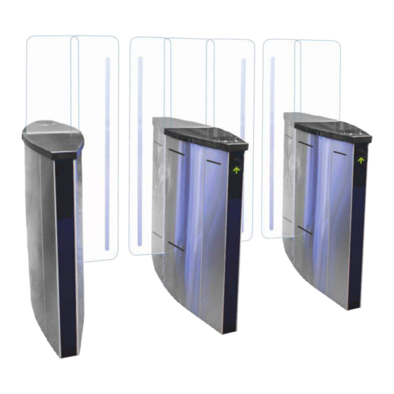
1.3.1 The turnstile modification depends on the number of access ways: 1) For arrangement of single access way the turnstile «JETPAN-1» " is a set of two similar in design pedestrian gates (Master and Slave) with one each of which has one glass leaf (reference... - Page 9 2) For arrangement of two or more access ways the turnstile «JETPAN-1» is a set of two one- leaf pedestrian gates (reference designation Т3.КСD.ХK) (Fig.1 b) and one or more auxiliary pedestrian gate «JETPAN-2» (Master/Slave)with one each of which has two glass leaf (reference designation Т3.КСD.ХK.Х).
- Page 10 1.3.3 Design of the «JETPAN-2» type turnstile (See Fig.5). The turnstile is an additional cabinet «JETPAN-2» (Master/Slave) with two leaves (glass panels). The number of additional cabinets is specified in order. The turnstile «JETPAN-2» operates only as part of the turnstile “JETPAN-1”. The additional cabinet includes: – base;...
- Page 11 4 – Glass panel (leaf); 8 – Base; 9 – Side panel (front and rear); 10 – Turnstile operating mechanism Fig. 5 – Design of the turnstile «JETPAN-2» Т3.КСD.ХK.X 1.3.4 Design, overall and installation dimensions of the turnstile are shown in Annex A.
-
Page 12: Design And Operation
1.4.1.4 Leaf 1 is made from 10 mm tempered glass and is located in the middle of the cabinet body on motion mechanism (1). Each leaf is actuated by separate servomotor. The additional cabinet «JETPAN-2» is equipped with two servomotors (one per each leaf), while the «JETPAN- 1» turnstile cabinets are equipped with one servomotor per each cabinet. - Page 13 8 – bracket retainer; 9 – retractable glass; 10 – retractable device rack 11 – tensioner cramp; 12 – balancing spring 13 – frame base; Fig.7– General appearance of and design of operating mechanism and control desk of the turnstile «JETPAN-1» (Master cabinet)
-
Page 14: Instrumentation, Tools And Accessories
1.4.3 3 Principle of operation 1.4.3.1 Access cycle: 1. In the initial state the turnstile glass blades are located perpendicular to the body block access. 2. The turnstile is opened for access in the direction "А" or "В" after the appropriate command from ACS or control panel is issued. - Page 15 • "FREE ACCESS IN THE DIRECTION B". • "FREE ACCESS IN BOTH DIRECTIONS". • "LOCK OF ACCESS IN THE DIRECTION А". • "LOCK OF ACCESS IN THE DIRECTION B". • "LOCK OF ACCESS IN BOTH DIRECTIONS". • «"ALARM". "INITIAL STATE" The turnstile is in this mode during energization and after completion of the turnstile access, if during access the mode is not changed to "LOCK", "FREE"...
- Page 16 The lock mode prevails over single and free access mode. It means that access can be locked at any time, thus, if within the blade closing area there is no any obstacle they will be closed. The controller will be in this mode until arrival of command "CANCELLATION OF ACCESS LOCK" via interface RS-485 from control panel.
- Page 17 Table 5 № Directio Connec Signal description and Description Designation tor/cont parameters INP1 1) logical «0» (02,2) ХТ4/1 («TO BE OPENED ENTRY Command "TO BE 2) logical «1» (3 5) A») OPENED FOR SINGLE INP2 / FREE ACCESS" 3) active level of ХТ4/2 («TO BE OPENED ENTRY...
- Page 18 Continued Table 5 1) type of output – open collector; 2) peak voltage on privacy key 60V; Output for connection of 3) peak current of audible alarm. The output public key 250mA; ХТ1/1 is active in case of 4) resistance of public unauthorized access key (0,48640) Ohm;...
- Page 19 1.6.2 Turnstile controller РСВ.201.01.00.00 1.6.2.1 Appearance of controller РСВ.201.01.00.00 is shown in Figure 9. 1.6.2.2 Description of operation The controller is designed to control DC motor, intended to move the turnstile blades, and electromagnetic brake installed on motor shaft. Control is performed based on the signals coming from magnetic sensor as well as from motor current sensor.
- Page 20 Table 6 № Descriptio Signal description and Direction Designation Connector parameters /contact 1) logical “0” X1/1 ENTRY «TO BE OPENED A» (0 1,7) V; 2) X1/2 ENTRY «LOCK» 2) logical “1” X1/3 ENTRY Not applicable (3,7 5) V; 3) Not applicable X1/4 ENTRY...
-
Page 21: Intended Use
2 INTENDED USE 2.1 Operation restrictions 2.1.1The turnstile must be used in the environment specified in p. 1.1.4 of this document subject to the specifications listed in section 1.2. IT IS FORBIDDEN: TO MISUSE THE TURNSTILE (See Section 1 "DESCRIPTION OPERATION");... - Page 22 − extension cord; − kit of end and pin wrenches; − kit of hexagons; − kit of screwdrivers; − hammer; − multimeter (tester); − measuring tape; − marker; − pliers, side cutters; − builder's level. Fig. 10 - Tools and accessories for layout and installation...
- Page 23 2.2.5. Total configuration of the «JETPAN»turnstile access ways Fig. 11–The «JETPAN» turnstile access way arrangement options WARNING: The damages occurred during the turnstile transportation are not covered by the manufacturer's warranty liabilities.
- Page 24 2.2.6. Installation procedure. The turnstile installation procedure is as follows: 1) The package integrity to be checked prior to unpacking. If package is damaged, then damages to be documented (picture to be taken, damage report to be made). 2) The turnstile to be unpacked and inspected for defects and damages as well as completeness to be checked according to the turnstile data sheet;...
- Page 25 The cabinet relative position and vertical installation of the turnstile to be complied with. Fig. 13 – Installation dimensions of the turnstile set «JETPAN-1» and «JETPAN-2» 6) The relevant holes to be drilled on the surface according to the marking due to diameter of anchors (12×120М10) for the turnstile fixation.
- Page 26 Cables to be run in corrugated or metal pipes prior to pulling to prevent damages. Fig. 14 – General view of connection between cabinets...
- Page 27 Option 1 Slave Master IROUT 1 IROUT 2 IROUT 3 IROUT 4 IROUT 5 IROUT 6 IROUT 7 IROUT 8 RS A2 RS B2 AUX 1 AUX 2 AUX 3 LED B R LED B G Wire 1.5 mm Wire 0.22(0.5) mm Wire 1.5 mm Option 2 Fig.
- Page 28 Fig.13; The turnstile to be fixed by means of anchors included in the scope of delivery Fig. 16 - General view of the «JETPAN-1» turnstile cabinet installation...
- Page 29 12) Turnstile connection: a) Power supply cable ~230 V to be connected (Fig. 17): - Phase (L) - to be connected to circuit breaker; - Neutral (N) to be connected to terminal ~230V; - Earth (РЕ) to be connected to earthing terminal (РЕ).
-
Page 30: Turnstile Preparation For Use
Fig.19 – Installation of card reader into the turnstile pedestrian gate «JETPAN» 2.3 Turnstile preparation for use 2.3.1 Commissioning guidelines Prior to the turnstile energization: 1) make sure of proper connection and good condition of all connecting cables; 2) clear the turnstile leaf swing area from foreign particles. - Page 31 2.3.2.1 When the turnstile is commissioned it is necessary to perform the inspections specified in Table 7. During inspections the wiring diagram according to Annex C and the control desk according to Annex B to be used Table 7 Operation Mode Setting LED display Functional check...
-
Page 32: Contingency Actions
Continued Table 7 "FREE" button to be Glass leaves 8. Free access pushed for access in Green arrow of authorized pushed inside in one direction chosen direction («A» or free access chosen turnstile opening and locked «B») "LOCK" direction is lit and red access access in button to be pushed to... -
Page 33: Maintenance
3 MAINTENANCE 3.1 General guidelines 3.1.1 Commissioning and subsequent maintenance of the turnstile to be performed only by the staff being in charge of the turnstile. 3.1.2 The turnstile to be serviced only by the staff having the relevant electrical safety qualification level according to the national requirements. -
Page 34: Routine Maintenance
Table 8 Detergent description Manufacturer Country of origin Stainless steel cleaning spray “Stainless Group of European Steel Cleaner And Polish” companies Cleaning fluid “Well Done” Well Done Hungary Stainless steel products and other metals XANTO United Kingdom cleaner “XANTO STEEL 3in1” «Dr.BECKMANN»... -
Page 35: Jetpan-1" Turnstile Blade Initialization Procedure
Wires to be checked. 4.3. «JETPAN-1» turnstile blade initialization procedure Initial setting of the blade zero position at the first activation of the turnstile: 1) Turn OFF the power supply; 2) Motor to be disconnected from PCB 201terminal: MOT1 (Fig.7);... - Page 36 6) The new initial position calibration The new initial position setting is completed.is completed Layout of board over Top view of the installed magnetic between magnetic axis and magnetic axis sensor magnetic sensor Fig. 21– General view of the «JETPAN»turnstile magnetic sensor...
-
Page 37: Postrepair Checkout
Fig. 22 – Magnetic sensor board PCB 730.01 4.4 Postrepair checkout The turnstile performance is checked after repair according to p. 2.3.2 of this OM. 5 TRANSPORTATION AND STORAGE 5.1 Turnstile storage It is forbidden to subject the turnstile to jerks and impacts during storage. Transportation trolleys to be used for handling of the turnstile. -
Page 38: Turnstile Transportation
gases and vapours causing metal corrosion. Air temperature during storage should not be below +500 С and above +400 С and relative air humidity should not be more than 80% at the temperature 20° С. 5.2 Turnstile transportation The ready-to-install turnstile to be transported according to the transportation regulations related to the relevant mode of transport, such as: –... - Page 39 "TiSO-PRODUCTION" LTD 14 Promyshlennaya str., 02088 Kiev, Ukraine Tel: +38 (044) 291-21-11 Tel./Fax: +38 (044) 291-21-02 E-mail: sales@tiso.global www.tiso.global SERVICE CENTER e-mail: service1@tiso.global Our equipment complies with requirements of the European Standards: EN ISO 12100:2010; EN 614-1:2006+A1:2009; EN 1037:1995+A1:2008; EN 60204-1:2006; EN 953:1997+A1:2009; ISO 3864:1995;...
-
Page 40: Annex А Overall And Installation Dimensions Of The ""Jetpan-1" Type Turnstile
Annex А (mandatory) Overall and installation dimensions of the “«JETPAN-1» type turnstile * Overall dimension for the turnstile with glass countertop Figure А.1 – Installation dimensions of the single turnstile T3.KCD.XK_/500/500... - Page 41 Continued Annex А Overall dimensions of the «JETPAN-1» and «JETPAN-2» type turnstile * Overall dimension for the turnstile with glass countertop Figure А.2 – Installation dimensions of group of the turnstiles T3.KCD.XK.X/500/500 and T3.KCD.XK_/500/500...
-
Page 42: Annex B Control Desk And Connection Diagram
Annex B (mandatory) Control desk and connection diagram 1 – control panel body; 5 – "FREE ACCESS" mode control button 2 – "SINGLE ACCESS" mode control 6 – "PANIC" mode control button button 3 – front plate; 7 – access direction LED display; 4 –... -
Page 43: Continued Annex B Control Panel And Connection Diagram
Continued Annex B Control panel and connection diagram Figure B.2 – Connection diagram of control panel AUIA.114.02.00.00... -
Page 44: Annex C.1 Wiring Diagram Of The "Jetpan" Type Turnstile
Annex C.1 (mandatory) Wiring diagram of the «JETPAN» type turnstile... -
Page 45: Annex D.1 Diagram Of The Turnstile Connection To Access Control System (Acs)
Annex D.1 (mandatory) Diagram of the turnstile connection to access control system (ACS) Relay 1 Relay 2 Door contact 1 Door contact 2 inp1 - "TO BE OPENED A" in pulse mode. When command is issued entry is activated for 5 sec. inp2- "TO BE OPENED B"... -
Page 46: Annex D.2 Diagram Of The Turnstile Connection To Access Control System (Acs)
Annex D.2 (mandatory) Diagram of the turnstile connection to access control system (ACS) inp1- " TO BE OPENED A" in pulse mode. When command is issued the input is activated for 5 sec. . inp - 2 " TO BE OPENED B" in pulse mode. When command is issued the input is activated for 5 seconds. -
Page 47: Annex D.3 Diagram Of The Turnstile Connection To Fire Alarm (Fa)
Annex D.3 (mandatory) Diagram of the turnstile connection to fire alarm (FA) inp1- " TO BE OPENED A" in pulse mode. When command is issued the input is activated for 5 sec. inp - 2 " TO BE OPENED B" in pulse mode. When command is issued the input is activated for 5 seconds. -
Page 48: Annex D.4 Diagram Of The Turnstile Connection To Control Panel
Annex D.4 (mandatory) Diagram of the turnstile connection to control panel 5 4 3 2 1...
Need help?
Do you have a question about the JETPAN and is the answer not in the manual?
Questions and answers