Table of Contents
Advertisement
Quick Links
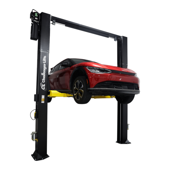
Installation, Operation & Maintenance Manual
V
ersymmetric®
Two Post
Surface Mounted Lift
CL10AV3
M
:
ODELS
CL10AV3-QC
(Q
C
)
UICK
YCLE
10,000
. C
LBS
APACITY
2500
.
A
LBS
PER
RM
2311 South Park Rd Louisville, Kentucky 40219
Email:
Challengerlifts@soe.freshdesk.com
Phone: 800-648-5438
IMPORTANT:
READ THIS MANUAL COMPLETELY BEFORE
INSTALLING OR OPERATING LIFT
Rev. 2024/06/11
Advertisement
Table of Contents

Related Manuals for Challenger Lifts Versymmetric CL10AV3 Series


Summary of Contents for Challenger Lifts Versymmetric CL10AV3 Series
- Page 1 Installation, Operation & Maintenance Manual ersymmetric® Two Post Surface Mounted Lift CL10AV3 ODELS CL10AV3-QC UICK YCLE 10,000 APACITY 2500 2311 South Park Rd Louisville, Kentucky 40219 Email: Challengerlifts@soe.freshdesk.com Phone: 800-648-5438 IMPORTANT: READ THIS MANUAL COMPLETELY BEFORE INSTALLING OR OPERATING LIFT Rev.
-
Page 2: Specifications
Model CL10A Installation, Operation and Maintenance ENERAL PECIFICATIONS See Figure 1 CL10A CL10A-2 CL10A-3 11’-2” or 11’- 8” 13’-2” or 13’- 8” 14’-2” or 14’- 8” Column Height 12’ 13’- 3” or 13’- 9” 14’- 3” or 14’- 9” * Ceiling Height Required 11’- 11”... -
Page 3: Vertical Clearance
Model CL10A Installation, Operation and Maintenance ERTICAL LEARANCE EAD ENTIRE MANUAL BEFORE ASSEMBLING INSTALLING OPERATING OR SERVICING THIS Check the height of the area where the lift is to be EQUIPMENT installed. Clearance should be calculated based on ROPER MAINTENANCE AND INSPECTION IS the full raised height of the lift. -
Page 4: Installation
Chalk line shorted or damaged goods. Do this for your own c. 4ft level protection. d. 10” adjustable wrench Challenger Lifts NOTIFY AT ONCE if any hidden e. Standard open-end wrenches 7/16”, 1/2", loss or damage is discovered after receipt. - Page 5 Model CL10A Installation, Operation and Maintenance 3) Determine the sheave location on the lower 4) Route cables as shown in Fig. 2 and Fig. 4. bracket based on the overall height and width of Ensure cables do not wrap around hoses during the lift at its chosen configuration.
- Page 6 Model CL10A Installation, Operation and Maintenance OCKING 12) Clean the hole inside and out. DUAL PENDANT 13) Assemble a washer and nut to the anchor with OR LIFTS WITH OPTIONAL nut just below impact section of bolt. Drive the CONTROL, REFER INSTALLATION anchor into the hole until the nut is 3/4”...
- Page 7 Model CL10A Installation, Operation and Maintenance inner overhead holes will be used. For the (-12”) 22) Install the idler bracket to the overhead beam width, the inner set of overhead holes will be using the rear set of holes on the idler side of used.
- Page 8 Model CL10A Installation, Operation and Maintenance 26) Mount synchronizer cables to carriages as one full turn. Again, tighten flared fitting finger tight, shown in Fig. 11a & 11b. then rotate flared fitting 1-1/2 hex flats (90 deg.). 27) Mount power unit to power column as shown in If installing at 114-1/2”...
- Page 9 Model CL10A Installation, Operation and Maintenance 1/4-20NC NUT 1/4 NYLON SPACER HYD. LINE CLAMP 1/4-20NC x 3/4 BOLT 3/8 HOSE CLAMP 3/8-16NC x 3/4 BOLT 3/8-16NC NUT Fig. 14 – Power Unit Hose 31) Thread 9/16-18 O-ring elbow ( ) into in hardware box power unit.
-
Page 10: Arm Installation
Model CL10A Installation, Operation and Maintenance overhead clear of moving parts and back out 42) Make sure all the arm bolts are tight. Slide all the through access slot in bottom of idler side column arms out so they are fully extended making sure extension. - Page 11 Model CL10A Installation, Operation and Maintenance YDRAULICS engaged and fully out against the tab when disengaged. Tighten idler column lower tab jam 50) Lower the lift to the floor and raise the lift nuts. approximately one foot. IMPORTANT: I F IDLER SIDE LOCK PAWL DOES NOT 51) Start with idler side first.
- Page 12 Model CL10A Installation, Operation and Maintenance FIELD FIELD FIELD FIELD CONNECTIONS CONNECTIONS CONNECTIONS CONNECTIONS (Normally Open) (Normally Open) (Normally Open) (Normally Open) ...
-
Page 13: Operation Procedure
Model CL10A Installation, Operation and Maintenance the case of frame engaging lift, ALI/LP-GUIDE, PERATION ROCEDURE Vehicle Lifting Points/Quick Reference Guide for AFETY OTICES AND ECALS Frame Engaging Lifts; in a conspicuous location in the lift area convenient to the operator. This product is furnished with graphic safety warning labels, which are reproduced on page 3 IMPORTANT SAFETY INSTRUCTIONS... -
Page 14: Lifting A Vehicle
• Check adapters for damage or excessive wear. readjust the arms. If the vehicle is stable, raise Replace as required with genuine Challenger Lifts the vehicle to a height a few inches above the parts. -
Page 15: Parts Breakdown
31058 ANCHOR BOLT, 3/4 x 5-1/2” Lg. Replace all worn, damaged, or broken parts with parts approved by Challenger Lifts Inc. or with parts meeting Challenger Lifts Inc. specifications. Contact your local Challenger Lifts Parts Distributor for pricing and availability. - Page 16 36096 BALL HANDLE – Power side ONLY Replace all worn, damaged, or broken parts with parts approved by Challenger Lifts Inc. or with parts meeting Challenger Lifts Inc. specifications. Contact your local Challenger Lifts Parts Distributor for pricing and availability.
- Page 17 ¼-20 x ¾ HEX FLANGE HEAD BOLT 40085 ¼-20 HEX FLANGE NUT Replace all worn, damaged, or broken parts with parts approved by Challenger Lifts Inc. or with parts meeting Challenger Lifts Inc. specifications. Contact your local Challenger Lifts Parts Distributor for pricing and availability.
- Page 18 4100342 5/16-18 HEX FLANGE NUT X 1/2” Lg. Replace all worn, damaged, or broken parts with parts approved by Challenger Lifts Inc. or with parts meeting Challenger Lifts Inc. specifications. Contact your local Challenger Lifts Parts Distributor for pricing and availability.
- Page 19 PARTS BREAKDOWN (continued) Fig E. Carriage & 3-Stage Arm Pack (B2202SD) Replace all worn, damaged, or broken parts with parts approved by Challenger Lifts Inc. or with parts meeting Challenger Lifts Inc. specifications. Contact your local Challenger Lifts Parts Distributor for pricing and availability.
- Page 20 38mm EXTERNAL RETAINING RING B2202SD ARM PACK, CL10, 3-STAGE Replace all worn, damaged, or broken parts with parts approved by Challenger Lifts Inc. or with parts meeting Challenger Lifts Inc. specifications. Contact your local Challenger Lifts Parts Distributor for pricing and availability.
- Page 21 Model CL10A Installation, Operation and Maintenance NOTES Page 21 CL10A-IOM-A.doc Rev 2024/06/11...
- Page 22 Model CL10A Installation, Operation and Maintenance REVISIONS Page 22 CL10A-IOM-A.doc Rev 2024/06/11...
Need help?
Do you have a question about the Versymmetric CL10AV3 Series and is the answer not in the manual?
Questions and answers