Table of Contents
Advertisement
Quick Links
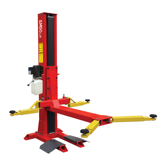
CHAIN-DRIVE SINGLE POST LIFT
Cargo Claims
If there is any missing or damaged
product during transportation, the
buyer must notate on the shipping
paperwork or refuse the shipment.
NOTATE ALL DAMAGE OR REFUSE
DAMAGED SHIPMENT!
Model: SL-7
△
DANGER
!
Read the entire contents of this manual before
using this product. Failure to follow instructions
and safety precautions could result in serious
injury or even death. Make sure all other
operators also read this manual. Keep this
manual near the machine so that it can be seen
by all users. By proceeding with installation and
operation, you agree that you are fully
understand the contents of this manual and take
full responsibility for the use of the product.
Original
Advertisement
Table of Contents

Related Manuals for AMGO Hydraulics SL-7


Summary of Contents for AMGO Hydraulics SL-7
- Page 1 Original CHAIN-DRIVE SINGLE POST LIFT Model: SL-7 △ DANGER Read the entire contents of this manual before using this product. Failure to follow instructions and safety precautions could result in serious Cargo Claims injury or even death. Make sure all other If there is any missing or damaged operators also read this manual.
-
Page 2: Table Of Contents
CONTENTS PROFILE ............................. 1 IMPORTANT SAFETY INSTRUCTIONS ................3 I. PRODUCT FEATURES AND SPECIFICATIONS ............ 5 II. INSTALLATION REQUIREMENT ................7 III. INSTALLATION STEPS ....................9 IV. EXPLODED VIEW ......................20 V. TEST RUN ........................... 26 VI. OPERATION INSTRUCTIONS ................. 28 VII. -
Page 3: Profile
PROFILE This installation and service manual is specially prepared for you. Your new lift is the product of over a decade of continuous research, testing and development and is the most technologically advanced lift on the market today. Please make sure to read through this manual before operating the lift. Record the information on the nameplate label here : Model No. - Page 4 SAFETY WARNING LABEL Fig.1...
-
Page 5: Important Safety Instructions
IMPORTANT SAFETY INSTRUCTIONS In order to properly maintain your product and ensure operator safety, it is the responsibility of the product owner to read and follow these instructions! 1. Ensure product installation full complies with all applicable local and national rules, ordinances and regulations;... - Page 6 the power supply before any circuit repair. Unplug in case the power supply is accidentally switched on during maintenance; 15. Warning! There is a risk of explosion. There are parts in the equipment that produce arc light and spark. Do not operate near flammable gas. This machine should not be placed in the lounge or basement;...
-
Page 7: Product Features And Specifications
Fig.2 I. PRODUCT FEATURES AND SPECIFICATIONS CHAIN-DRIVE SINGLE POST MODEL SL-7 FEATURES · Lifting capacity: 7000lbs · Compact design. · Hydraulic cylinder is designed and made on high standard, with utilizing imported oil seal in cylinder. · Self-lubricating UHMW polyethylene sliders and bronze bush. - Page 8 MODEL SL-7 SPECIFICATIONS Arm Swings View Fig.3 Lifting Lifting Time Model Capacity Overall Minimum Max. Lifting Height Overall Width Height Pad Height Without extension Include extension adapters adapters 84S( 110V) 7000lbs 108 7/8" 84 1/2 ” 4 3 /8" SL-7 32S (220V) 72 1 /4"~74 1 3/16"...
-
Page 9: Installation Requirement
II. INSTALLATION REQUIREMENT A. TOOLS REQUIRED Rotary Hammer Drill(Φ19) Carpenter’s Chalk √ √ Hammer Screw sets √ √ Tape Measure(7.5mm) Level Bar √ √ English Spanner(12″) √ Pliers √ Wrench set:(10#, 13#, 14#, Socket Head Wrench:(4#,5#,6#) √ √ 15#,17#,19#,24#,27#) Fig.4... - Page 10 Equipment storage and installation requirements. 1.Store the equipment in a dry, non-moldy, non-flammable environment; 2.The equipment is only allowed for indoor installation and use. Outdoor installation is prohibited; 3.When installing the equipment, take safety precautions according to the instructions to avoid device damage;...
-
Page 11: Installation Steps
D. Power supply 1.You are required to use a licensed and qualified electrician for the installation process. 2.The power supply should be 110VAC/60HZ, with a cord larger than 12AWG, and must be properly grounded. △ DANGER All l tifi d e ec r ca w r ng mus e per orme y a cense an cer... - Page 12 △ CAUTION I t lli th lift ith l 3° d t i j ns a ng on a sur ace w s opes more o n ury or even death. The lift is designed for installation on a flat and level surface only. (Defined as no more than 3/8”...
- Page 13 4. Open the parts box, and check all the parts according to the parts list. Fig.9 5. Open parts bag, check all the parts according to the parts bag list. Parts bag Fig.10 C. Confirm the installation position and place the base onto it. (See Fig.11) Fig.11...
- Page 14 D. Fix anchor bolts. Using the prescribed rotary hammer drill, and drill all the anchor holes and install the anchor bolts. Then tighten the anchor bolts. (See Fig. 12) Note: Torque of anchors is 150N.m (1327612.5lbf.in), . Minimum embedment of anchors is 4 3/8”.
- Page 15 3. Position the column onto the base, align the mounting holes, and install with bolts. Check the column plumbness with level bar, adjust with shims if necessary. (See Fig.15) 45 M20*50 Hex bolt with flat washer, lock washer 62/63 Adjust with 3/64” or 5/64” shims if necessary.
- Page 16 F. Install power unit, retainer and connect oil hose. Install power unit. (See Fig.17) M8*25 hex bolt w/ φ20*φ8*3 rubber ring, M8 nylo k nut Fig.17 2. Connect oil hose. Install the 90° fitting to the power unit, then connect it with the oil hose that comes from the cylinder.
- Page 17 3. Install retainer 12 M6*8 round head bolt w/ φ6 flat washer Fig.19 Note: Tighten all the hydraulic fittings after installation. 4. Fill the reservoir with hydraulic oil. Note: In consideration of power unit’s durability and keep the equipment running in the perfect condition, please use hydraulic oil 46#.
- Page 18 Power supply wires Fig.20 △ DANGER th lift if th If th hi l o no use e w res are amage or severe y worn. e ve c e rises without noticing damage or extreme wear, carefully lower the vehicle to the ground. Once the lift is on the ground, remove it, disconnect the power, and arrange for protection.
- Page 19 I. Install lifting arms. 1. Install inside arms. Align the inside lifting arm with the hole, insert arm pin and limited with clip ring. Fig.22 2. Engage arm lock and moon gear. Follow the steps blow to engage arm lock and moon gear. 2.
- Page 20 3. Install outside arms. Align the outside lifting arm with the hole, insert the arm pin, and tighten with M8*12 flat head bolt. (See Fig.26) Arm pin M8*12 flat head bolt Fig.26 4. Operation of arm lock release handle ② ②...
- Page 21 J. Install fabric curtain cover. (See Fig.28) Follow the steps below to install the fabric curtain cover. 3 M6*95 hook bolt, w/ φ6 flat washer and M6 nylo k nut Just assemble the nut to flush with the hook bolt, don’t tighten yet 2.
-
Page 22: Exploded View
IV. EXPLOEDED VIEW Fig.29... - Page 23 PARTS LIST FOR SL-7 Description Item Part# Top plate 11101013 M12*30 hex bolt w/ M12 nylo k nut 1001085013 Hook bolt M6*95 w/ φ6 flat washer, M6 Nylo k Nut 1101085015 Fabric curtain cover L= 101 3/ 16” 11101042 Chain pulley seat assy.
- Page 24 Description Item Part# Lock washer φ10 10209039 10209021 Hex nut M10 Oil hose 1/4”*65 11/32” (L= 1660mm) 10101027 11101023 Base M20*50 Hex bolt w/ φ20 flat washer, φ20 lock washer 1001085005 M8*12 Hex bolt w/ flat washer, lock washer 1001045004 Stackable adapter bracket 11203035 Stackable adapter 3 ”...
- Page 25 4.1 Rubber pad assy. (10203054) exploded view: Description Item Part# M8*20 socket bolt 10420043 Double screwed rubber pad 10203043 Support frame 11203026 Elastic retaining ring 10203041 Adjusting rod 11203025 Elastic retaining ring 10203042 Adjusting sleeve 11203024 Fig.30 4.2 Outside arm assy. (10101033) exploded view: Fig.31 Description Part#...
- Page 26 4.3 Inside arm assy. (left) (10101034)exploded view: Fig. 32 Description Item Part# QTY. Socket bolt M8*25 (w/ flat washer, lock 1001045006 washer) 10209035 Moon gear 11101020 Outer arm Round head bolt M8*12 10201149 Inner arm 11102006 4.4 Cylinder (10207010) exploded view: Fig.
- Page 27 Description Item Part# QTY. Piston rod 11207027 Piston 11207028 O-ring 10206069 Support ring 10620053 Y- ring OSI 10620054 O-ring 10630027 10206071 Hex nut Cylinder adjusting sleeve 11207029 Dust ring 10217078 O-ring 10520058 Head cap 11207030 Bleeding plug 10201034 O-ring 10207031 11207032 Bore weldment 4.5 Chain pulley seat assy.
-
Page 28: Test Run
Illustration of hydraulic valves for power unit UP button Relief valve Oil return port Release valve Oil output port Throttle valve Handle for Oil output port release valve Check valve Fig. 35 V. TEST RUN 1. Adjust the lowering speed (Fig.36) If necessary, you can adjust the lowering speed of the lift by turning the throttle valve clockwise to decrease it, or counterclockwise to increase the lower speed. - Page 29 2. Test with load A test with load should be conducted after the above adjustments have been completed. Run the lift at low level several times first, when there is no other abnormal phenomenon, run the whole process. Repeat the above adjustment if there is any abnormal phenomenon. Tips: There will be vibration during the first operation without load, load and run several times, the vibration will disappear naturally after the air in the hydraulic system is exhausted!
-
Page 30: Operation Instructions
VI. OPERATION INSTRUCTIONS To lift vehicle 1. Keep operation site clean; 2. Lower the lifting arm to the lowest position; 3. Retract the lifting arm to the shortest position; 4. Swing lifting arms straight to both sides; 5. Drive the vehicle onto the lift. To get off conveniently, make the cab towards outside instead of the column side;... -
Page 31: Maintenance Schedule
VII.MAINTENANCE SCHEDULE Monthly: 1. Tighten all connecting bolts; 2. Check all fitting, bolts and pins to ensure proper connections; 3. Lubricate slider, chain with lubricant; Make a visual inspection of all hydraulic hoses/lines for possible wear or leakage; 5. Check safety device and make sure in proper condition; 6. -
Page 32: Trouble Shooting
VIII. TROUBLE SHOOTING TROUBLE CAUSE REMEDY 1. Replace 1. Button does not work 2.Wiring connections in good 2. Repair all wiring connections condition Motor does 3. Replace 3. AC contractor burned out not run 4. Repair or replace 4. Motor burned out 1. -
Page 33: Car Lift Safety Tips
IX. CAR LIFT SAFETY TIPS Put this safety tips in a place where you can always alert the operator. Please reference to the lift manufacturer’s manual for specific information about the lift. 1. Check the lift daily. If the machine breaks down or has damaged parts, do not operate, and use the parts of original equipment to repair. - Page 34 AMGO HYDRAULIC CORPORATION Address: SC Division : 1931 Joe Rogers Jr Blvd, Manning, SC 29102, USA TX Division : 4310 Adler Dr., Suite #200, Dallas, TX 75211, USA Tel : (803) 505-6410 Fax: (803) 505-6410 Manual Part No.: 72210409 Revision Date: 2023/10...
Need help?
Do you have a question about the SL-7 and is the answer not in the manual?
Questions and answers