Table of Contents
Advertisement
Quick Links
Advertisement
Table of Contents

Related Manuals for AMGO Hydraulics SL-6


Summary of Contents for AMGO Hydraulics SL-6
- Page 1 SINGLE POST LIFT Model:SL-6...
-
Page 2: Table Of Contents
II. INSTALLATION REQUIREMENT ..................3 III. STEPS OF INSTALLATION ..................... 5 IV. EXPLODED VIEW ....................13 V. TEST RUN ......................15 VI. OPERATION INSTRUCTIONS ................. 17 VII. MAINTENANCE SCHEDULE ................... 18 VIII. TROUBLE SHOOTING ..................19 IX. PARTS LIST FOR SL-6 ..................20... -
Page 3: Product Features And Specifications
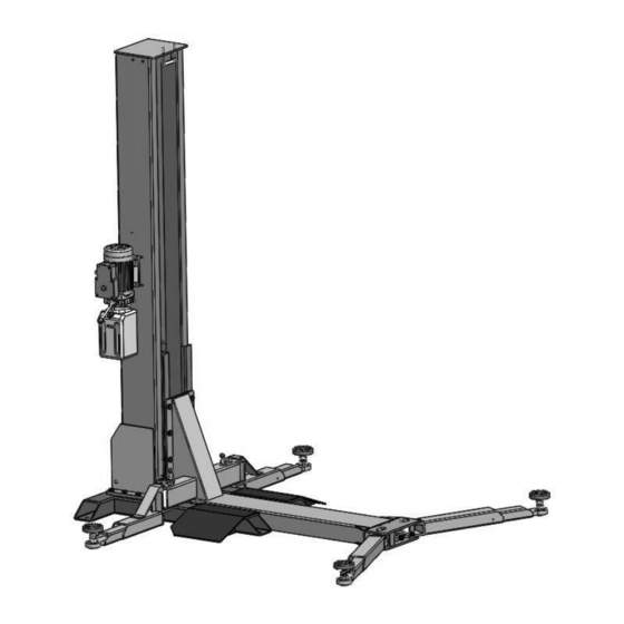
PRODUCT FEATURES AND SPECIFICATIONS CHAIN-DRIVE SINGLE POST MODEL SL-6 FEATURES · Compact design. · Hydraulic cylinders, designed and made on ANSI standard, utilizing NOK oil seal in cylinder. · Self-lubricating UHMW Polyethylene sliders and bronze bush. · Manual release safety lock, two-stage lock system ·... - Page 4 Arm Swings View Fig.2...
-
Page 5: Installation Requirement
INSTALLATION REQUIREMENT A. TOOLS REQUIRED Rotary Hammer Drill(Φ19) Carpenter’s Chalk Hammer Screw sets Level Bar Tape Measure(7.5mm) English Spanner(12″) Pliers Wrench set:(10 Socket Head Wrench:(4 # # # # # #... - Page 6 B. SPECIFICATIONS OF CONCRETE (See Fig. 4) Specifications of concrete must be adhered to the specification as following. Failure to do so may result in lift and/or vehicle falling. 1. Concrete must be thickness 4’’ minimum and without reinforcing steel bars and must be dried completely before the installation.
-
Page 7: Steps Of Installation
STEPS OF INSTALLATION III. A. Location of installation Check and insure the installation location (concrete, layout, space size etc.) is suitable for lift installation. B. Check the parts before assembly Packaged lift and hydraulic power unit (See Fig. 5) Column Power Unit Base Carriage... - Page 8 2. Take off the packaging on the machine. Take off the packing rack. 3. Move aside the parts and check the parts according to the shipment parts list(See Fig.6 & 7) Fig.6 Fig.7 4. Check the parts of the parts bag according to the parts bag list (See Fig.8) Fig.8...
- Page 9 C. Lay the base flat to the ground, confirm installation place according to the ground state, the main purpose is to save space. (See Fig.9) Fig.9 D. Install column and lift platform 1. Lay the column flat to the ground.(See Fig.10) Fig 10 2.
- Page 10 3. Fix column to the base plate. (See Fig.12) 4. Fix lifting platform to carriage.(See Fig.13) Fig.13 Fig.12...
- Page 11 E. Install motor fixed plate, power unit and oil hose(See Fig.14) Note: Tighten the oil hose fitting and power unit fitting to avoid oil leakage; Pay attention to the direction of power unit fitting. Tighter the screw with 19# wrench set after install power unit fitting.
- Page 12 F. Install plastic barrier (See Fig.15) Clip support Clip support The plastic barrier pass through from here Fig.15 G. Connect the power source according to the data on plate of power unit Note: For the safety of operators, the power wiring must contact the floor well Single phase motor (See Fig.
- Page 13 H. Install lifting arms(see Fig.17); Lowing the carriages down to the lowest position, then use the 6# wrench to loosen the nut (See Fig. 18)Adjust the arm lock as arrow direction (See Fig. 19). Adjust moon gear and arm lock to make it to be good engagement, then tighten the nut of arm lock (See Fig.
- Page 14 I. Tighten all the hydraulic fittings, and fill the reservoir with hydraulic oil. Note: In consideration of Hydraulic Power Unit’s durability and keep the equipment running in the perfect condition, please use Hydraulic Oil 46#. J. Using level to measure and adjust the column to be vertical . Use level to measure the column by front and side to make sure the column...
-
Page 15: Exploded View
Ⅳ. Exploded View Model:SL-6 Fig.24... - Page 16 Cylinder exploded view Fig.25 Exploded view of manual power unit 110V/60Hz/1 phase Fig.26...
-
Page 17: Test Run
Illustration of hydraulic valve for hydraulic power unit Power unit of 110V/60Hz/1PH(Fig.27) Oil return port Relief valve Solenoid valve Oil output port Check valve Throttle valve Fig.27 V. TEST RUN Adjust the lower speed (See Fig.28) You can adjust the lower speed of the lift if needing: Loosen the Fixing Nut of the Throttle Valve, and then turn the Throttle Valve clockwise to decrease the lower speed, or counterclockwise to increase the lower speed. - Page 18 2. Test with load After finishing the above adjustment, test running the lift with load. Run the lift in low position for several times first, make sure the lift can rise and lower without abnormal phenomena. And then test run the lift to the top completely. If there are anything improper, repeat the above adjustment.
-
Page 19: Operation Instructions
OPERATION INSTRUCTIONS To lift vehicle 1. Keep clean of site near the lift; 2. Position lift arms to the lowest position; 3. To shortest lift arms; 4. Open lift arms; 5. Position vehicle beside of the lifting arm, cab should at the other side of the column; 6. -
Page 20: Maintenance Schedule
MAINTENANCE SCHEDULE VII. Monthly: 1. Re-torque the anchor bolts to 150 N.M; 2. Check all connectors, bolts and pins to insure proper mounting; 3. Lubricate cable with lubricant; 4. Make a visual inspection of all hydraulic hoses/lines for possible wear or leakage; 5. -
Page 21: Trouble Shooting
TROUBLE SHOOTING VIII. TROUBLE CAUSE REMEDY Button does not work 1. Replace button Wiring connections are not in good 2. Repair all wiring connection condition Motor does AC contactor burned out 3. Repair or replace contactor not run Motor burned out 4. -
Page 22: Parts List For Sl-6
PARTS LIST FOR SL-6 Item Part# Description QTY. Note 101023 Base assembly 201020 90° Fitting for Cylinder 101014 Column assembly 101015 Carriage assembly 101002 Hex Bolt 201114 Lock Washer 209128 Washer 101001 Hex Bolt 420175 Hex Nut Connect pin assembly... - Page 23 Item Part# Description QTY. Note 209059 Anchor Bolt 101013 Top Plate assembly 206023 Self Locking Nut 217069 Hex Bolt 206079 Cap Head Bolt 209012 Spring Pin 203002 Power Side Safety Device 209007 Safety Spring 209009 Cap Head Bolt 209008 Safety Cover 206002 Safety Pin 206003A...
- Page 24 Item Part# Description QTY. Note 520023 Snap Ring 209026 Spring 209025 Spring Pin 101016 Lifting Platform Assy. 201002 Hex Socket Bolt 101006 Screw 217048 Cable clap 071103 Hydraulic Power Unit Parts For Hydraulic Cylinder 65-1 207027 Piston Rod 65-2 207028 Piston 65-3 206069...
- Page 25 Relief valve 81400266 Plug 81400284 81400452 Handle for release valve 81400451 Plastic ball 10209020 Nut for release valve 81400125 Shim for release valve 81400124 Valve seat 81400449 Release valve 070001 Check valve 070002 Oil suction pipe 81400375 Oil return pipe 81400376 Clamps 81400364...
- Page 26 AMGO HYDRAULIC CORPORA TION 1931 Joe Rogers Blvd, Manning, South Carolina, Zip:29102 Tel: (803) 505-6410 fax: (803) 505-6410 72245801 09/2017...
Need help?
Do you have a question about the SL-6 and is the answer not in the manual?
Questions and answers