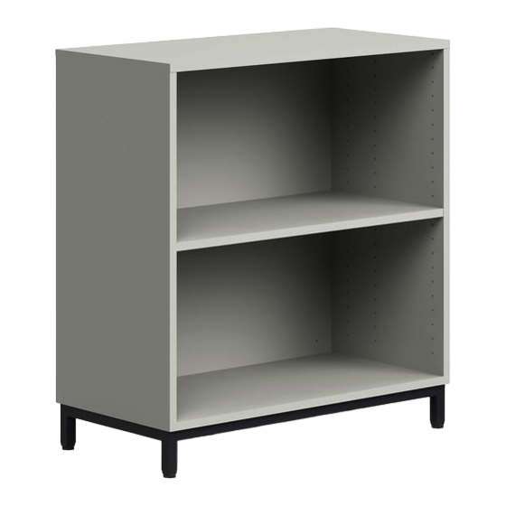
Summary of Contents for SMITH SYSTEM Constellate Double Sided Library Storage
- Page 1 Assembly Instructions Constellate Double Sided Library Storage If you have damaged or missing components, please contact customer service at 1-800-328-1061 Document #: 179725 REVISED: 02/2024...
- Page 2 Hardware and Components 36” MOBILE LEG PACK (PN:60442) MOBILE HARDWARE PACK (PN:60413) Document #: 179725 REVISED: 02/2024...
- Page 3 Hardware and Components 48” MOBILE LEG PACK (PN:60443) MOBILE HARDWARE PACK (PN:60413) Document #: 179725 REVISED: 02/2024...
- Page 4 Hardware and Components 36” MOBILE BOARD KIT (PN:70039) 48” MOBILE BOARD KIT (PN:70042) 11”X34” SHELF PACK (PN:60374) 36” Qty. = 2 48” Qty. = 4 Document #: 179725 REVISED: 02/2024...
- Page 5 Hardware and Components CASTER MODELS ONLY (PN:60021 x4) GLIDE MODELS ONLY (PN:60372) OPTIONAL EXTERNAL HOOK (PN:60554) Document #: 179725 REVISED: 02/2024...
-
Page 6: Assembly Guidelines
Assembly Guidelines Special Notes: • TOOLS REQUIRED: o Drill w/ T25 Torx driver bit (bit provided). o Rubber Mallet o Drill w/ 3/16”x3” hex driver bit (bit provided) – For glide assembly only. o Optional: 36” Soft Jaw Clamps o NOTE: Do NOT use impact drills. •... - Page 7 Assembly Instructions 1. Unpack and confirm all parts are present. Find a smooth flat surface to assemble the unit. NOTE: 36” Double Sided unit shown for these instructions. 2. Take one of the wood side panels (the ones with multiple shelf holes) and install a left and right leg as shown.
- Page 8 Assembly Instructions 4. Lay side panel on the smooth flat surface. Take the bottom panel and secure it to the legs using four (4) wood screws as shown. Do NOT overtighten screws. 5. Secure bottom bracket to side and bottom panels with four (4) wood screws as shown.
- Page 9 Assembly Instructions 6. Take the back panel and attach it to the bottom panel using three (3) wood dowels as shown. If the holes on the edge of the back panel do not line up with the bottom panel, flip the back panel around to use the other edge with holes. 7.
- Page 10 Assembly Instructions 8. Take the other side panel and secure it to the bottom panel using four (4) wood screws as shown. Then secure the bottom bracket to the side and bottom panels using four (4) wood screws. Do NOT overtighten screws. 9.
- Page 11 Assembly Instructions 10. Take the header brackets and line them up to the top edge of the legs as shown. The top of the header bracket should be along the same plane as the top of the leg and the front of the header bracket should be parallel with the front of the leg. 11.
- Page 12 Assembly Instructions 12. Take the top panel and attach it to the back panel using three (3) wood dowels as shown. 13. Secure the top panel to the legs and header brackets using 12 wood screws. Do NOT overtighten. Document #: 179725 REVISED: 02/2024...
- Page 13 Assembly Instructions 14A. For caster units, install four (4) casters into the bottom of the legs, it is a press fit. 14B. For glide units, install four (4) glides using supplied Allen key. The Allen key head is accessed through a hole in the bottom of the glide. Do NOT overtighten. Once installed there should be no gap or movement in the glide.
- Page 14 Assembly Instructions 15. Flip unit over onto its casters or glides. Install four (4) shelf pegs into the holes in the side panels at the desired height for each shelf. 16. Insert the shelf at an angle and slowly lower one side at a time onto the pegs. There are cutouts in the shelf that allow the shelf to sit on the pegs securely.
- Page 15 Assembly Instructions 1. OPTIONAL: The external hook can be installed on the side of the unit in the opening between the top of the side panel and the top panel. 2. Install external hook as shown. Do NOT overtighten. OPTIONAL ASSEMBLY COMPLETE Document #: 179725 REVISED: 02/2024...


Need help?
Do you have a question about the Constellate Double Sided Library Storage and is the answer not in the manual?
Questions and answers