
Related Manuals for SMITH SYSTEM Constellate Single Sided Library Storage


Summary of Contents for SMITH SYSTEM Constellate Single Sided Library Storage
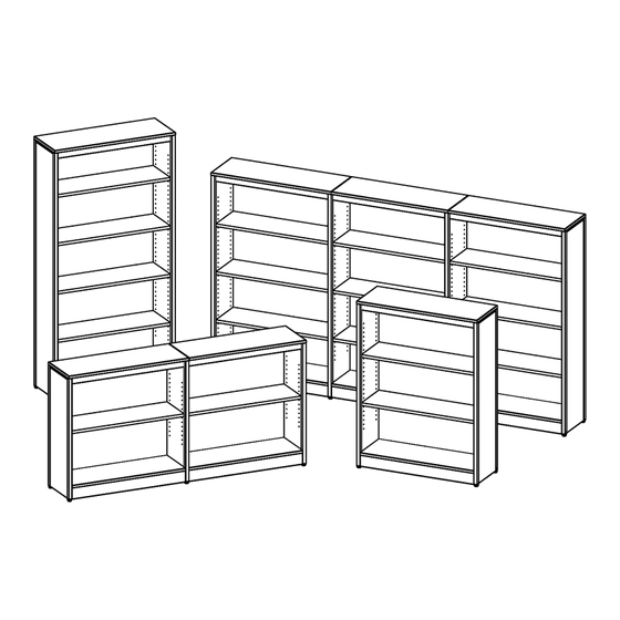
- Page 1 Assembly Instructions Constellate Single Sided Library Storage If you have damaged or missing components, please contact customer service at 1-800-328-1061 REVISED: 05/2024 Document #: 179724...
- Page 2 Hardware and Components 36” STARTER LEG PACK (PN:60430) STARTER HARDWARE PACK (PN:60381) ANCHOR KIT (PN:60375) Document #: 179724 REVISED: 05/2024...
- Page 3 Hardware and Components 36” ADDER LEG PACK (PN:60431) SEE PAGE #2 FOR DETAIL ADDER HARDWARE PACK (PN:60380) Document #: 179724 REVISED: 05/2024...
- Page 4 Hardware and Components 48” STARTER LEG PACK (PN:60433) SEE PAGE #2 FOR DETAIL SEE PAGE #2 FOR DETAIL 48” ADDER LEG PACK (PN:60434) SEE PAGE #3 FOR DETAIL SEE PAGE #2 FOR DETAIL Document #: 179724 REVISED: 05/2024...
- Page 5 Hardware and Components 60” STARTER LEG PACK (PN:60436) SEE PAGE #2 FOR DETAIL SEE PAGE #2 FOR DETAIL 60” ADDER LEG PACK (PN:60437) SEE PAGE #3 FOR DETAIL SEE PAGE #2 FOR DETAIL Document #: 179724 REVISED: 05/2024...
- Page 6 Hardware and Components 72” STARTER LEG PACK (PN:60439) SEE PAGE #2 FOR DETAIL SEE PAGE #2 FOR DETAIL 60” ADDER LEG PACK (PN:60437) SEE PAGE #3 FOR DETAIL SEE PAGE #2 FOR DETAIL Document #: 179724 REVISED: 05/2024...
- Page 7 Hardware and Components 36” STARTER BOARD KIT (PN:70037) 36” ADDER BOARD KIT (PN:70038) 48” STARTER BOARD KIT (PN:70040) Document #: 179724 REVISED: 05/2024...
- Page 8 Hardware and Components 48” ADDER BOARD KIT (PN:70041) 60” STARTER BOARD KIT (PN:70043) 60” ADDER BOARD KIT (PN:70044) Document #: 179724 REVISED: 05/2024...
- Page 9 Hardware and Components 72” STARTER BOARD KIT (PN:70045) 72” ADDER BOARD KIT (PN:70047) 11”X34” SHELF PACK (PN:60374) 36” Qty. = 1 48” Qty. = 2 60” Qty. = 3 72” Qty. = 4 Document #: 179724 REVISED: 05/2024...
-
Page 10: Special Notes
Hardware and Components OPTIONAL EXTERNAL HOOK (PN:60554) Special Notes: • TOOLS REQUIRED: o Drill w/ T25 Torx driver bit (bit provided). o Rubber Mallet o Optional: 36” Soft Jaw Clamps o NOTE: Do NOT use impact drills. o For Bottom Panel Removal ▪... - Page 11 Assembly Instructions 1. Unpack and confirm all parts are present. Find a smooth flat surface to assemble the unit. These units can be built vertically. NOTE: 48” Single Sided units are shown for these instructions. 2A. Take one of the wood side panels (the ones with multiple shelf holes) and install a front left and back left leg as shown.
- Page 12 Assembly Instructions 3A. With a helper holding the legs tightly to the panel, secure legs to the side panel using eight (8) #10x5/8” wood screws installing them with the provided T25 Torx bit. Do NOT overtighten screws. Repeat this for all other side panels and set aside. HINT: You can use 36”...
- Page 13 Assembly Instructions 4A. With a helper, attach a left and right side panel to the back panel by making sure to line up the pegs on the legs with the holes in the back panel. The bottom edge of the back panel should rest on the lip of the bottom brackets on the legs.
- Page 14 Assembly Instructions 5A. With a helper holding the side panels tightly to the back panel, secure side panels to the back panel using eight (8) #10x5/8” wood screws installing them with the provided T25 Torx bit. Do NOT overtighten screws. 5B.
- Page 15 Assembly Instructions 6. Use two (2) of the ¼” wood dowels and insert them into the back edge of the false bottom panel. With the pilot holes facing up, slide this panel under the leg brackets as shown so that the dowels are inserted into the back panel. There will be a slight gap between the back panel and the false bottom panel.
- Page 16 Assembly Instructions 8. Take the back support backet and secure it to the false bottom panel and back panel, using four (4) #10x5/8” wood screws. Do NOT overtighten screws. 9. Use two (2) of the ¼” wood dowels and insert them into the back side of the front kick plate panel.
- Page 17 Assembly Instructions 10. Secure the front kick plate panel to the leg brackets using four (4) #10x5/8” wood screws. Do NOT overtighten screws. 11. Take the header bracket and line it up to the top edge of the legs as shown. The top of the header bracket should be along the same plane as the top of the leg, and the front of the header bracket should be parallel with the front of the leg.
- Page 18 Assembly Instructions 12. Secure header bracket with two (2) #10x7/16” machine screws to the legs as shown. Make sure to keep the header bracket parallel with the top and front of the leg. Do NOT overtighten, you just need to get the screw snug. 13B.
- Page 19 Assembly Instructions 14B. If building two or more units, with a helper holding the side panels tightly to the back panel, secure side panels to the back panel using eight (8) #10x5/8” wood screws installing them with the provided T25 Torx bit. Do NOT overtighten screws. Repeat steps 6 through 12 for the other units.
- Page 20 Assembly Instructions . If building two or more units, insert two (2) ¼” wood dowels into the top edge of the back panel on the end unit and lower the top panel onto the dowels as shown. . If building two or more units, insert two (2) ¼” wood dowels into the top edge of the next back panel and lower the adder top panel onto the dowels as shown.
- Page 21 Assembly Instructions 16A. Secure the top panel to the legs and header using twelve (12) #10x5/8” wood screws installing them with the provided T25 Torx bit. Do NOT overtighten screws. 16B. If building two or more units, secure each top panel to the legs and header using twelve (12) #10x5/8”...
- Page 22 Assembly Instructions 17. Take the bottom panel and, while using the rubber mallet, gently tap in two (2) plastic retaining clips. Make sure to put the short side in the holes of the bottom panel as shown. Do NOT tap too hard as the clips can break. 18.
- Page 23 Assembly Instructions 19B. If building two or more units, repeat steps 17 and 18 for each unit. 20. For all units, install four (4) shelf pegs into the holes on the side panels at the desired height for each shelf. Document #: 179724 REVISED: 05/2024...
- Page 24 Assembly Instructions 21. Insert the shelf at an angle and slowly lower one side at a time onto the pegs. There are cutouts in the shelf that allow the shelf to sit on the pegs securely. 22. For all units, install all remaining shelves. Document #: 179724 REVISED: 05/2024...
- Page 25 Assembly Instructions 23. Position the anchor bracket as shown below on the back of the unit, keeping the bracket inside the hatched area. The anchor bracket can also be attached to the top of the unit in the same manner. Attach the bracket to the back panel using two (2) wood screws.
- Page 26 Assembly Instructions 1. OPTIONAL: The external hook can be installed in the opening between the top of the side panel and the top panel. 2. Install external hook as shown. Do NOT overtighten. OPTIONAL ASSEMBLY COMPLETE Document #: 179724 REVISED: 05/2024...
- Page 27 Disassembly Instructions 1. If you are adding additional units to an existing assembly, you need to remove the bottom panel to expose the screws. To do this, take a wide putty knife and wedge it in between the bottom panel and the front kick plate panel. This must be done at least 7”...
- Page 28 Disassembly Instructions 3. Once the bottom panel is free, set it to the side for reassembly. Proceed to remove the side panel and assemble the new units as previously shown in the above instructions. DISASSEMBLY COMPLETE Document #: 179724 REVISED: 05/2024...
Need help?
Do you have a question about the Constellate Single Sided Library Storage and is the answer not in the manual?
Questions and answers