Table of Contents
Advertisement
Quick Links
Advertisement
Table of Contents

Related Manuals for STMicroelectronics MB467


Summary of Contents for STMicroelectronics MB467
- Page 1 STMicroelectronics MB467 Airbag EVA Board UM0178 User manual Rev 1 February 2006...
- Page 2 BLANK...
- Page 3 Airbag Eva Board Introduction The MB467 Airbag Eva Board is a complete demonstrator of an airbag system based on STMicroelectronics devices. The board implements a flexible and open design demonstrating the capability of the STMicroelectronics 16/32bit microcontrollers and safing devices for airbag applications.
-
Page 4: Table Of Contents
UM0178 Table of Contents Introduction ..........6 Features . - Page 5 UM0178 Reset ............23 4.10 CPU Board connector .
- Page 6 UM0178 List of tables Table 1. Satellite connector ............14 Table 2.
- Page 7 MB467 Airbag Eva Board system block diagram ....... . 11...
-
Page 8: Introduction
1 Introduction Introduction The MB467 Airbag Eva Board is intended as a low cost development platform to demonstrate the capability of the L9658/L9654 safing and L4998 voltage regulator ASIC’s. The board includes also a CPU board connector to interface with ST10/ST30 EVA board. -
Page 9: Devices
UM0178 1 Introduction Devices The MB467 Airbag Eva Board mounts the following devices: L9658 octal squib driver and quad sensor interface ASIC for safety application – 64-pin TQFP version – 8 deployment drivers – interface with 4 satellite sensors –... -
Page 10: Before You Start
UM0178 2 Before you start Before you start This section describes operations needed before powering up the board. Please, refer to Chapter 4 on page 10 for detailed information on board configuration and jumper settings. Jumper settings For the location and (default) settings of the various jumpers, please refer as follows: Close the jumper J51 to supply the board. -
Page 11: Using The Board
UM0178 3 Using the board Using the board How to exercise diagnostic functionality 3.1.1 Arming interface Arming communication between micro and ASIC can be exercised by interrupting clock signal of the specific SPI. This can be done opening the jumper J20. 3.1.2 Squibs This board support both real squibs or simulated loads. -
Page 12: Hardware
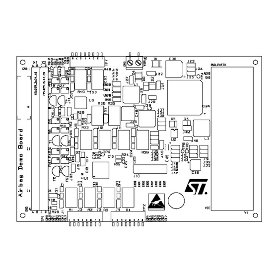
UM0178 4 Hardware Hardware This chapter describes all the hardware modules of the board. Overview The MB467 Airbag Eva Board is a specific platform for airbag with SPI interface. Figure 2. MB467 Airbag Eva Board layout block diagram L9654 SQUIB... -
Page 13: L9658 Octal Squib Driver And Quad Sensor Interface Asic
UM0178 4 Hardware Figure 3. MB467 Airbag Eva Board system block diagram L9658 octal squib driver and quad sensor interface ASIC L9658 is intended to deploy up to 8 squibs and to interface up to 4 satellites. Two satellite interfaces can be used to interface Hall sensors. Squib drivers are sized to deploy 1.2A minimum for 2ms minimum during load dump and 1.75A minimum for 1ms minimum during... -
Page 14: L9654 Quad Squib Driver And Dual Sensor Interface Asic
UM0178 4 Hardware Programmable independent current trip points for each satellite channel Support Manchester protocol for satellite sensors Supports for variable bit rate detection Independent current limit and fault timer shutdown protection for each satellite output Short to ground and short to battery detection and reporting for each satellite channel 5.5MHz SPI interface Satellite message error detection Hall effect sensor support on satellite channels 3 and 4. -
Page 15: L4998 Safety Power Regulator Asic
UM0178 4 Hardware L4998 Safety Power Regulator ASIC The L4998 integrated circuit is intended for automotive applications.The main feature set is described below: Boost regulator able of sourcing up to 90mA output current Buck regulator operating in Continuous Conduction Mode able of sourcing up to 250 mA output current One 5.0V linear regulator (V ) able of sourcing up to 200mA output current... -
Page 16: Satellite Spi Interface
UM0178 4 Hardware the current limit condition was removed, this fault condition does not interfere with the operation of any of the other output channels. Channels 3 and 4 of the L9658 can by used to provide an analog feed back current as a 1/ 100th ratio of the sense current in this mode internal FIFO and decoder are bypassed. -
Page 17: Arming Interface
UM0178 4 Hardware Table 2. Satellite jumpers Name Figure Description Figure 4 Interrupt SPI communication for Satellite and Deployment Figure 4 Enable load simulation for L9658 satellite channel 1 through DICH1 Figure 4 Enable load simulation for L9658 satellite channel 2 through DICH2 Enable load simulation for L9658 satellite/sensor channel 3 through Figure 4 DICH3... -
Page 18: Arming Spi Interface
UM0178 4 Hardware There are on board two different deployment enables for L9658 and L9654. When these pins are asserted, L9658/L9654 are able to turn on its high (SQH) and low side (SQL) drivers upon receiving a valid deployment command or a MOS diagnostic request. When a deployment is initiated, it cant be terminated, except during a reset event. -
Page 19: Asic Diagnostic Functionality
UM0178 4 Hardware Daisy chain configuration Arming SPI interface shall support a daisy-chain configuration. In this configuration, the processor can send arming commands to multiple L9658 devices without having to use additional pins. The functioning is underline in the following figure: Figure 6. -
Page 20: Squib And Deployment Drivers
UM0178 4 Hardware Figure 7. Arming jumpers location Squib and deployment drivers The on-chip deployment drivers are designed to deliver 1.2A (min.) at 6.9V VRES. Deployment current is be 1.2A (min.) for 2ms (min.). The high side driver can survives deployment with 1.47A, 40V at VRES and SQL is shorted to ground for 2.5ms. -
Page 21: Functional Description
UM0178 4 Hardware 4.7.2 Functional description The Airbag Eva Board supports up to 12 squibs. Upon receiving a valid deployment condition, the respective SQH and SQL drivers are turned on. SQH and SQL drivers are also turned on momentarily during a MOS diagnostic. Otherwise, SQH and SQL are inactive under any normal, fault, or transient conditions. -
Page 22: Table 6. Squib Dummy Loads
UM0178 4 Hardware Name Figure Description SQL7 Figure 8 Low Side Driver Output for Channel 7 for L9658 SQL9 Figure 8 Low Side Driver Output for Channel 0 for L9654 SQL10 Figure 8 Low Side Driver Output for Channel 1 for L9654 SQL11 Figure 8 Low Side Driver Output for Channel 2 for L9654... -
Page 23: Power Supply
J16-J19 Power supply The MB467 Airbag Eva Board is supplied using an external 12V supply. All other required voltages (5V, 8V and 35V) are provided by the on-board Power Regulator. A connected microcontroller board can also be supplied via the V pins available on the CPU board connector (5V, 200mA). -
Page 24: Table 7. Power Supply Jumpers
UM0178 4 Hardware A soft start function (C ) of V linear regulator can be obtained by closing jumper J46. slew Closing J46 connect an external capacitor to the C pin of the SPR producing a linear slew voltage ramp at the start-up. The SPR uses this linear voltage to limit the slew rate of the output. -
Page 25: Reset
UM0178 4 Hardware Figure 9. Power supply jumpers location J23-25 J48-50 J31-33 Reset Power on reset is driven by the L4998 Safety Power Regulator (SPR). The SPR provides an output (RST) to indicate the regulation status of VCC. The RST output is asserted low whenever VCC falls below its low voltage threshold or VCC rises above its over-voltage threshold. -
Page 26: Cpu Board Connector
UM0178 4 Hardware Figure 10. Reset jumper 4.10 CPU Board connector The CPU board Connector allows interfacing this board to a ST30F7xx/ST10F3xx Eva Boards. Signals provided on the connector are listed in Table 10. on page Table 10. CPU Board connector pinout Column Name Description... -
Page 27: Prototyping Area
Chip select for Arming Interface of L9658 4.11 Prototyping area A standard 100mils prototyping area is available for user’s application. 4.12 Jumpers summary Table 11. summarizes jumpers available on the MB467 Airbag Eva Board. Table 11. Jumpers summary Jumper Name Figure Description... - Page 28 UM0178 4 Hardware Jumper Name Figure Description L9658 satellite channel 2: SATELLITE Figure 4 Open: real satellite (ICH2 on J6 pin 1) Closed: simulated satellite (load driven by DICH2) L9658 satellite channel 3: SATELLITE Figure 4 Open: real satellite (ICH3 on J7 pin 1) Closed: simulated satellite (load driven by DICH3) L9658 satellite channel 4: SATELLITE...
- Page 29 UM0178 4 Hardware Jumper Name Figure Description IREF Figure 9 IREF partitioning Soft start function (C Figure 9 SLEW slew partitioning Figure 9 partitioning Figure 9 partitioning Figure 9 VIGN Figure 9 Power supply switch SQUIB Figure 8 Driver Output for Channel 0 for L9654 SQUIB Figure 8 Driver Output for Channel 1 for L9654...
-
Page 30: Connectors Summary
UM0178 4 Hardware 4.13 Connectors summary Table 12. summarizes connectors available on the MB467 Airbag Eva Board. Table 12. Connectors summary Name Figure Description SQH0 Figure 8 High Side Driver Output for Channel 0 for L9658 SQH1 Figure 8 High Side Driver Output for Channel 1 for L9658... - Page 31 UM0178 4 Hardware Name Figure Description GND9 Figure 8 Power Ground for Loop Channel 0 for L9654 GND10 Figure 8 Power Ground for Loop Channel 1 for L9654 GND11 Figure 8 Power Ground for Loop Channel 2 for L9654 GND12 Figure 8 Power Ground for Loop Channel 3 for L9654 29/37...
-
Page 32: Revision History
UM0178 5 Revision history Revision history Date Revision Changes 18-Oct-2005 Initial release. 30/37... -
Page 33: Appendix A Bill Of Materials
UM0178 5 Revision history Appendix A Bill of materials Table 13. Bill of materials Item Reference Part C1,C2,C3,C4,C5,C6,C7,C8,C11,C13,C17,C19,C20,C21,C22,C23,C2 4,C25,C26,C27,C28,C29,C30,C31,C32,C33,C44,C51,C54,C55,C56, 100nF C57,C59,C61,C63,C64,C65,C66,C67,C68,C69,C70 C9,C12,C14,C15,C16,C18,C60,C62 10pF C10,C58 330pF 3000 MF C35,C39,C42,C43,C48 100nF 100MF 10MF 220MF 47MF 4.7MF 220nF 470nF 10nF C52,C53 470pF D1,D4 SMBJ24A-TR MBRS1100T3 ES1B... - Page 34 UM0178 5 Revision history R1,R2,R3,R4,R22,R23,R24,R25,R35,R36,R48,R49 R5,R6,R12,R13,R19,R20,R26,R27,R42,R43,R46,R47 R7,R11,R14,R17,R31,R37,R40,R41,R44 R8,R18,R21,R28,R45,R50 4.7K R9,R38 11.5K R10,R39 R15,R16 6.8K R29,R30 12.4K TP1,TP2,TP7 Barr Screw TP3,TP4,TP5,TP6 TP_CMS T1,T2,T3,T4,T5,T6 2N4401 L9658 L4998 L9654 ED102 Header 2x34 AB Header 2x34 CD 32/37...
-
Page 35: Appendix B Schematics
UM0178 5 Revision history Appendix B Schematics Figure 11. L4998 Safety Power Regulator 33/37... -
Page 36: Figure 12. L9658 Octal Squib Driver And Quad Sensor Interfaces
UM0178 5 Revision history Figure 12. L9658 Octal Squib Driver and Quad Sensor Interfaces GND4 GND0 GND4 GND0 SQL4 SQL0 SQL4 SQL0 SQH4 SQH0 SQH4 SQH0 VRES VRES VRES4 VRES0 VRES VRES VRES5 VRES1 SQH5 SQH1 SQH5 SQH1 SQL5 SQL1 SQL5 SQL1 GND5... -
Page 37: Figure 13. L9654 Quad Squib Driver And Dual Sensor Interfaces
UM0178 5 Revision history Figure 13. L9654 Quad Squib Driver and Dual Sensor Interfaces MOSI_A MISO MOSI_A MISO SCLK_A MSG2 SCLK_A SCLK SCLK GND11 GND9 GND2 GND0 SQL11 SQL9 SQL2 SQL0 SQH11 SQH9 SQH2 SQH0 VRES VRES VRES2 VRES0 VRES VRES VRES VRES... -
Page 38: Figure 14. Connector To Cpu Board
UM0178 5 Revision history Figure 14. Connector to CPU board GND0 GND1 GND1 GND2 GND3 GND4 GND5 GND6 GND7 RESETB SCLK MOSI MISO DICH3 DICH4 DICH5 DICH6 CS_S1 CS_D1 AOUT AOUT2 GND9 GND10 GND11 GND12 Header 2x34 AB Header 2x34 AB MSG2 BCKFLT DICH1... - Page 39 Please Read Carefully: Information in this document is provided solely in connection with ST products. STMicroelectronics NV and its subsidiaries (“ST”) reserve the right to make changes, corrections, modifications or improvements, to this document, and the products and services described herein at any time, without notice.
Need help?
Do you have a question about the MB467 and is the answer not in the manual?
Questions and answers