Table of Contents
Advertisement
Quick Links
EMX
PROFESSIONAL SCRUBBING MACHINES
USE AND MAINTENANCE MANUAL
TRANSLATION OF THE ORIGINAL INSTRUCTIONS DOC.
10129622 - Ver. AA - 09-2023
The constructive elements and content of this manual, including the structure, text, diagrams, images and logo, are the exclusive property of FIMAP S.P.A..
They are protected, both collectively and individually, by the current regulations regarding intellectual property (including copyright laws), and cannot be either wholly or partially copied or imitated. Any
reproduction, reprocessing, distribution or dissemination is strictly prohibited.
Advertisement
Table of Contents

Subscribe to Our Youtube Channel
Related Manuals for Fimap EMX


Summary of Contents for Fimap EMX
- Page 1 10129622 - Ver. AA - 09-2023 The constructive elements and content of this manual, including the structure, text, diagrams, images and logo, are the exclusive property of FIMAP S.P.A.. They are protected, both collectively and individually, by the current regulations regarding intellectual property (including copyright laws), and cannot be either wholly or partially copied or imitated. Any...
-
Page 3: Table Of Contents
CONTENTS CONTENTS ................................3 DEFINITION OF LEVELS OF WARNING ......................6 GENERAL SAFETY REGULATIONS ........................6 GENERAL DESCRIPTION ............................ 6 SYMBOLS USED IN THE MANUAL........................7 TECHNICAL DESCRIPTION (DISCOID SCRUBBING VERSION) ................ 7 TECHNICAL DESCRIPTION (CYLINDRICAL SCRUBBING VERSION) ............... 8 TECHNICAL DESCRIPTION (ORBITAL VERSIONS) .................... - Page 4 ALARM SCREEN (PRO VERSIONS) ........................81 OPTIONAL FUNCTIONS ............................. 82 SOS DEVICE (PRO VERSIONS WITH FFM SYSTEM – FIMAP FLEET MANAGEMENT WI-FI & GSM) ..82 TAG INSERTION .............................. 82 AUTOMATIC DETERGENT DOSING SYSTEM (PRO VERSIONS WITH FSS SYSTEM – FIMAP SOLUTION SAVER) ................................
- Page 5 DRAINING THE SOLUTION TANK ........................104 CLEANING THE SOLUTION TANK FILTER-CAP ....................105 CLEANING DETERGENT CANISTER (VERSIONS WITH FSS SYSTEM – FIMAP SOLUTION SAVER) ..105 CLEANING DETERGENT CANISTER (VERSIONS WITH AUTOMATIC DETERGENT DOSING SYSTEM USING AQUÆ® TECHNOLOGY) ..........................107 EXTRAORDINARY MAINTENANCE WORK ....................
-
Page 6: Definition Of Levels Of Warning
DEFINITION OF LEVELS OF WARNING DANGER: indicates an imminent dangerous situation that, unless avoided, will result in death or serious injuries. WARNING: Indicates a potentially dangerous situation that, unless avoided, could cause death of serious injury. ATTENTION: Indicates a potentially dangerous situation that, unless avoided, could cause slight or moderate injuries. -
Page 7: Symbols Used In The Manual
TECHNICAL DESCRIPTION (DISCOID SCRUBBING VERSION) TECHNICAL DESCRIPTION (DISCOID SCRUBBING VERSION) The EMX E or EMX B or EMX BT machine uses the mechanical action of a disc-shaped brush with the added action of a chemical solution brought to the brush through a water system. -
Page 8: Technical Description (Cylindrical Scrubbing Version)
TECHNICAL DESCRIPTION (CYLINDRICAL SCRUBBING VERSION) TECHNICAL DESCRIPTION (CYLINDRICAL SCRUBBING VERSION) The EMX BTS machine uses the mechanical action of two cylindrical brushes with the added action of a chemical solution brought to the brushes through a water system. The machine can clean a wide range of flooring and... -
Page 9: Serial Number Plate
SERIAL NUMBER PLATE SERIAL NUMBER PLATE The serial number plate is positioned inside the machine, above the electrical system cover carter. It indicates the general machine characteristics, in particular the serial number. The serial number is a very important piece of information and should always be provided together with any request for assistance or when purchasing spare parts. -
Page 10: Main Machine Components
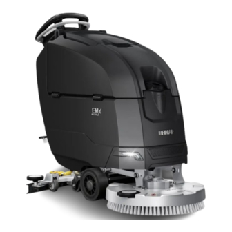
MAIN MACHINE COMPONENTS Scrubbing brush head Parking brake Front headlights Front wheels Solution tank Rear wheels Solution tank inlet cap Recovery tank Recovery tank cover Control handlebar recovery tank drainage tube Solution tank capacity level hose Solution tank filter Detergent solution adjustment tap Brush head body control pedal LED lights on-board charger Adjustment screw for squeegee tilt... - Page 11 Control handlebar PRO version, see Control handlebar BT BASE version, see “DASHBOARD (PRO VERSION)” on “DASHBOARD (BASIC VERSION WITH page TRACTION)” on page Control handlebar B BASE version, see Control handlebar E BASE version, see “DASHBOARD (BASIC VERSION)” on “DASHBOARD (ELECTRIC VERSION)” page on page - 11 -...
-
Page 12: Technical Data
TECHNICAL DATA N.B.: for all other technical data, contact the FIMAP service centre of reference or the one closest to you, or visit the website www.fimap.com. IS of U.M. TECHNICAL DATA 50 E [International System] Rated voltage [IEC 60335-2-72; IEC 62885-9] Rated frequency [IEC 60335-2-72;... - Page 13 IS of U.M. TECHNICAL DATA 43 B 50 B 43 BT 50 BT [International System] Rated voltage [IEC 60335-2-72; IEC 62885-9] Nominal input power 0,92 0,92 1,07 1,07 [IEC 60335-2-72; IEC 62885-9] Working gradeability with GVW [IEC 60335-2-72; IEC 62885-9] Machine working weight (gross weight - GVW) [IEC 60335-2-72;...
- Page 14 EMX PRO EMX PRO EMX PRO EMX PRO IS of U.M. TECHNICAL DATA 43 BT 50 BT 50 BTO 50 BTS [International System] Rated voltage [IEC 60335-2-72; IEC 62885-9] Nominal input power 0,92 0,92 1,25 1,27 [IEC 60335-2-72; IEC 62885-9] Working gradeability with GVW [IEC 60335-2-72;...
-
Page 15: Symbols Used On The Machine
SYMBOLS USED ON THE MACHINE Position symbol for the brush head control pedal: It is used at the rear of the solution tank to identify the brush head control pedal. Position symbol for the detergent solution adjusting tap: It is used at the back of the solution tank to identify the detergent solution adjustment knob. - Page 16 Solution tank filling symbol: Located on the left side of the machine's solution tank to indicate the amount of water or detergent solution in the tank. Position symbol for the brake: It is used on the left side of the solution tank to identify the brake control lever.
- Page 17 Symbol for maximum temperature for filling the solution tank: It is used at the front of the solution tank to indicate the maximum temperature the water must have to safely fill the solution tank, see “FILLING THE SOLUTION TANK” on page Recovery tank drainage hose symbol: It is used on the left side of the recovery tank to identify the recovery tank discharge pipe, see...
- Page 18 Warning symbol removal only by authorised personnel: It is used in the electrical system cover carter to warn the operator that removal of the casing should be done only by persons authorised by FIMAP. - 18 -...
-
Page 19: Labels Used On The Machine
LABELS USED ON THE MACHINE Label indicating that touching the brush when moving is prohibited: It is used to indicate to the operator that it is forbidden to approach the brush with the hands while it is in motion. Daily maintenance label: It is used to remind the operator to close the tap at the end of work and to perform daily maintenance on all filters in the machine, see “MAINTENANCE PLAN”... - Page 20 Battery charging instruction label (battery-powered version with on-board charger): In battery-powered versions, it is used to indicate to the user what procedures should be carried out for proper charging of the battery box, see “RECHARGING THE BATTERIES (BATTERY-POWERED VERSIONS)” on page Prohibition to vacuum hazardous elements label: In mains-powered versions, it is used to indicate to the user that it is absolutely forbidden to inhale glowing particles or flammable and/or explosive dust and/or liquids with the machine and...
- Page 21 Battery box warning label (battery-powered version): In battery-powered versions, it is used to indicate to the user that during the charging phase the cells could leak highly flammable hydrogen gas, see the "GENERAL SAFETY RULES" document delivered with the machine documentation. Warning label - disconnect mains cable before maintenance (electric version): In versions with mains power supply, it is used to indicate to the user that before carrying out any kind of maintenance, the power cable must be disconnected.
- Page 22 Water system filter maintenance warning label: It is used to warn the user to service the water system filter each time the machine is used, “MAINTENANCE PLAN” on page Prohibition to vacuum hazardous elements label: In battery-powered versions, it is used to indicate to the user that it is absolutely forbidden to inhale glowing particles or flammable and/or explosive dust and/or liquids with the machine and to operate in their vicinity.
- Page 23 Label indicating the need to see the Use and Maintenance Manual: Indicates the need to see the use and maintenance manual before using the machine. Label indicating machine supply voltage: In mains-powered versions, it is used to indicate to the user that there is a danger of electrocution at 220-230 volts.
- Page 24 Label warning about the risk of crushed hands: Applied to the solution tank to indicate the areas where hand crushing hazards are present. Label for ON-OFF main switch: In mains-powered versions, it is used to identify the position of the primary main switch to the user. - 24 -...
- Page 25 Label for ON-OFF key switch: It is used to identify the position of the key switch to the user. Label for brush uncoupling system: In the BASIC version machine it is used in the lower left part of the control handlebar to identify the switch that controls the brush uncoupling system, see “BRUSH UNCOUPLING FUNCTION (DISCOID SCRUBBING VERSION)”...
- Page 26 In the PRO version machine, it is used in the lower right part of the control handlebar to identify the switch that controls the automatic detergent dosing system, see “AUTOMATIC DETERGENT DOSING SYSTEM (PRO VERSIONS WITH FSS SYSTEM – FIMAP SOLUTION SAVER)” on page - 26 -...
- Page 27 It is used at the top of the pump box, found inside the battery compartment, to indicate to the user what warnings should be taken to take advantage of the automatic chemical dosing system, see “AUTOMATIC DETERGENT DOSING SYSTEM (PRO VERSIONS WITH FSS SYSTEM – FIMAP SOLUTION SAVER)” on page...
- Page 28 Recommended pH label for the detergent in the automatic chemical dosing system (optional): It is used on the detergent canister to indicate to the user the recommended pH range that the detergent should have in order to make best use of the automatic chemical dosing system, see “DETERGENT SOLUTION VERSIONS WITH FSS SYSTEM”...
- Page 29 Warning label for cleaning system without chemical cleaners (optional): It is used on the detergent canister to indicate to the user what warnings should be taken to take advantage of the chemical-free cleaning system, see “DETERGENT SOLUTION VERSIONS WITH FSS SYSTEM PAIRED WITH AQUÆ® TECHNOLOGY” on page - 29 -...
-
Page 30: Control Station
CONTROL STATION The machine has an easy and user-friendly control station, comprised of mainly the following: Control panel. Squeegee support control lever. Brush head control pedal. Detergent solution regulation tap. DASHBOARD (ELECTRIC VERSION) DASHBOARD (ELECTRIC VERSION) The control panel, in versions with mains power supply, consists mainly of the following: Control handlebars. -
Page 31: Dashboard (Basic Version With Traction)
(VERSIONS WITH TRACTION)” on page Valid only for machine versions with automatic Wifi-GSM fleet management, service message activation switch, see “SOS DEVICE (PRO VERSIONS WITH FFM SYSTEM – FIMAP FLEET MANAGEMENT WI-FI & GSM)” on page User presence lever. Main key switch. -
Page 32: Control Display (Basic Version)
CONTROL DISPLAY (BASIC VERSION) CONTROL DISPLAY (BASIC VERSION) In battery-powered versions, the basic control display is composed of the following: Battery charge level graphic symbol, see “BATTERY SYSTEM CHARGE LEVEL INDICATOR (BATTERY-POWERED BASIC VERSION)” on page Battery charge level graphic icon, see “BATTERY SYSTEM CHARGE LEVEL INDICATOR (BATTERY- POWERED BASIC VERSION)”... -
Page 33: Control Display (Pro Version)
“POWER MODE WORKING PROGRAM (PRO VERSION)” on page Graphic symbol used to identify that the automatic detergent dosing system is active, see “AUTOMATIC DETERGENT DOSING SYSTEM (PRO VERSIONS WITH FSS SYSTEM – FIMAP SOLUTION SAVER)” on page - 33 -... -
Page 34: Preparation Of Machine
WARNING: the descent ramp must have an inclination and a capacity such as not to damage the machine or be damaged during the transit of the machine, contact the FIMAP service centre technician to obtain the net weight of the machine. -
Page 35: Machine Safety
The machine is secured to the footboard with wedges that lock the wheels; remove these wedges. Verify that the brush head body is in the home position (raised off the floor), if not, press the pedal (1) to the end of the stroke, slide it to the left, and release it (Fig.1). Check that the squeegee body is in the home position (raised off the floor), if not, rotate the lever upward (2) (Fig.2). -
Page 36: Securing The Machine (Battery-Powered Version)
SECURING THE MACHINE (BATTERY-POWERED VERSION) SECURING THE MACHINE (BATTERY-POWERED VERSION) • Check the main switch is on "0". If it isn't, make a quarter turn anti-clockwise with the key (4) (Fig.4). • Remove the key from the instrument panel. • Grasp the handle (5) and turn the recovery tank cover (6) to its maintenance position (Fig.5). -
Page 37: How To Move The Machine
• Remove the key from the instrument panel. • Disconnect the plug (12) in the power cable from the mains power socket (13) (Fig.10). DANGER: to prevent damaging the mains socket, disconnect power cable by pulling the plug directly, and not the cable. -
Page 38: Type Of Battery To Be Used (Battery-Powered Versions)
For battery maintenance and recharging, follow the instructions contained in the document provided by the battery manufacturer. When the batteries are dead, they must be disconnected by a trained technician from your local FIMAP service center or the one closest to you; using suitable lifting devices, remove the batteries from the machine and take them to a specific disposal centre. -
Page 39: Inserting The Batteries In The Machine (Battery-Powered Version)
VERSION) VERSION) The insertion of the batteries inside the machine must be done by a trained technician from the relevant FIMAP service center or the one closest to you. WARNING: FIMAP declines all responsibility for any damage to property or injury persons in the event that the batteries are replaced by an unauthorized technician. - Page 40 Placement of acid batteries 12-TP-90: place the batteries (8) in the relevant compartment, with the '+' and '-' poles facing each other. Use the jumper cable (9) to connect the two batteries (8) so that the voltage is 24V. Connect the battery cable (10) to the remaining free poles.
-
Page 41: Recharging The Batteries (Battery-Powered Versions)
ATTENTION: to prevent unintentional rotation of the recovery tank, turn it until the rope (3) is fully tensioned (Fig.2). WARNING: the following operations must be carried out by specialised personnel from the FIMAP service centre of reference or the one closest to you. An incorrect connection of the connector may cause a malfunction of the device. -
Page 42: Recharging With An Internal Machine Charger
The battery charger in the machine is programmed by the factory with the following type of charging curve: GelGeneric, to change the type of charging curve contact your local FIMAP service centre or the one nearest to you; Alternatively, you can send an email to service@fimap.com, or visit the website at www.fimap.com... - Page 43 WARNING: if, during the battery charging phase, the LEDs in the battery charger display make a series of non-compliant flashes, stop charging the batteries and contact the relevant FIMAP service centre or the one nearest to you; Alternatively, you can send an email to service@fimap.com, or visit the website www.fimap.com •...
-
Page 44: Inserting Water System Filter
INSERTING WATER SYSTEM FILTER INSERTING WATER SYSTEM FILTER Before using the machine for the first time the water system filter needs to be reset, for shipping reasons the filter cap has been removed. To insert the filter cap into the solution tank: Take the machine to the maintenance area. - Page 45 Check that the filter (4) under the cap is positioned correctly (Fig.4) in order to prevent impurities and dirt from getting inside, which can cause the machine's water system to malfunction. Fill the solution tank. N.B.: the amount of solution inside the tank is indicated by the coloured ball inside the level tube (5) on the left-hand side of the machine (Fig.5).
-
Page 46: Detergent Solution
DETERGENT SOLUTION DETERGENT SOLUTION DETERGENT SOLUTION VERSIONS WITHOUT FSS SYSTEM DETERGENT SOLUTION VERSIONS WITHOUT FSS SYSTEM On machine versions without the automatic chemical dosing system after filling the solution tank with clean water, proceed as follows: Take the machine to the usual place for filling the solution tank. Perform all the operations required to secure the machine. -
Page 47: Detergent Solution Versions With Fss System
DETERGENT SOLUTION VERSIONS WITH FSS SYSTEM The FSS (FIMAP SOLUTION SAVER) system allows the dispensing of water and detergent to be dosed separately. In this way, only the necessary amount of water and the correct percentage of detergent are used according to the type of dirt to be removed, avoiding waste or excessive quantities of solution which can then be difficult to remove. - Page 48 Fill the canister (5) with the desired cleaning agent. ATTENTION: always use detergents which have a manufacturer's label that indicates that they are suitable for use with floor scrubbing machines. Do not use acid or alkaline products or solvents without this indication. WARNING: the dosing system is particularly suitable for frequent maintenance cleaning operations.
-
Page 49: Detergent Solution Versions With Fss System Paired With Aquæ® Technology
DETERGENT SOLUTION VERSIONS WITH FSS SYSTEM PAIRED WITH DETERGENT SOLUTION VERSIONS WITH FSS SYSTEM PAIRED WITH AQUÆ® TECHNOLOGY AQUÆ® TECHNOLOGY In machine versions with the automatic chemical dosing system associated with AQUÆ® technology, after filling the solution tank with water hardness <5 °fH (very light water) proceed as follows: Take the machine to the usual place for filling the solution tank. - Page 50 Fill the canister with the desired all-purpose cleaner. WARNING: FIMAP defines multipurpose detergents as those ordinary cleaning products with a pH between 6 and 8 and that do not contain: oxidising agents, chlorine or bromine, formaldehyde, mineral solvents. Close the cap (5) correctly to prevent liquid leaking out when working (Fig.7).
-
Page 51: Mounting Brushes Or Drive Discs (Discoid Scrubbing Version)
MOUNTING BRUSHES OR DRIVE DISCS (DISCOID SCRUBBING VERSION) MOUNTING BRUSHES OR DRIVE DISCS (DISCOID SCRUBBING VERSION) To mount the brush or drive disc in the brush head, follow the steps below: Take the machine to the maintenance area. Perform all the operations required to secure the machine. See “MACHINE SAFETY”... -
Page 52: Fitting Brushes (Cylindrical Scrubbing Version)
FITTING BRUSHES (CYLINDRICAL SCRUBBING VERSION) FITTING BRUSHES (CYLINDRICAL SCRUBBING VERSION) To assemble the brushes on the brush head, proceed as follows: Take the machine to the maintenance area. Perform all the operations required to secure the machine. See “MACHINE SAFETY” on page CAUTION: it is recommended to wear the appropriate PPE (Personal Protective Equipment), suitable for the work to be carried out. -
Page 53: Assembling The Abrasive Pad (Orbital Versions)
ASSEMBLING THE ABRASIVE PAD (ORBITAL VERSIONS) ASSEMBLING THE ABRASIVE PAD (ORBITAL VERSIONS) To mount the abrasive pad in the orbital brush head body, proceed as follows: Take the machine to the maintenance area. Perform all the operations required to secure the machine. See “MACHINE SAFETY”... - Page 54 Insert the vacuum tube (5) in the sleeve (6) in the squeegee body (Fig.4). WARNING: The squeegee comes pre-adjusted, however if necessary see “ADJUSTING THE SQUEEGEE RUBBER BLADES” on page 115. - 54 -...
-
Page 55: Work Preparation Checklist
Contact your FIMAP service centre of reference, or that which is closest to you; Alternatively, you can send Check for any fluid leaks an email to service@fimap.com, or visit the website at www.fimap.com Contact your FIMAP service centre of reference, or that which is closest to you;... - Page 56 Contact your FIMAP service centre of reference, or Check that the gasket on the recovery tank cover is that which is closest to you; Alternatively, you can send not damaged or worn an email to service@fimap.com, or visit the website at www.fimap.com - 56 -...
-
Page 57: Working Programs (Valid For Pro Versions)
WORKING PROGRAMS (VALID FOR PRO VERSIONS) The PRO version machine can be used with the following working programs: 1. ECO MODE: for light maintenance cleaning tasks, using fewer resources and operating at a low noise level, “ECO MODE WORKING PROGRAM (PRO VERSION)” on page 57). -
Page 58: Power Mode Working Program (Pro Version)
N.B.: By selecting the ECO MODE working program, the working parameters (machine speed; the performance of the suction motor; the detergent solution flow) are automatically changed. The parameters pre-set on a scale of 1 to 3 are as follows: Detergent Speed Suction Solution... -
Page 59: Manual Mode Working Program (Pro Version)
MANUAL MODE WORKING PROGRAM (PRO VERSION) MANUAL MODE WORKING PROGRAM (PRO VERSION) With the MANUAL MODE working program, it is the operator who evaluates and chooses the parameters based on the cleaning requirements that arise during the course of the work activities. To switch from the ECO MODE or POWER MODE or PROGRAM ZONE program to the MANUAL ZONE program, simply change one of the performance levels. -
Page 60: Working Mode
WORKING MODE TRANSFER WORKING MODE TRANSFER WORKING MODE In the TRANSFER working mode, both the brush head and the squeegee are in their resting positions. This working mode is used to transfer the machine from the work site to the maintenance site. To use the machine in transfer mode, do the following: Carry out all the checks listed in the “WORK PREPARATION CHECKLIST”... -
Page 61: Transfer Mode (Electric Version)
TRANSFER MODE (ELECTRIC VERSION) TRANSFER MODE (ELECTRIC VERSION) • Check that the main switch (7) (Fig.6) is in the '0' position, otherwise press the switch. ATTENTION: the primary main switch is set to '0' when the LED light inside it is off. •... -
Page 62: Scrubber Working Mode
The machine is now in the transfer working mode. SCRUBBER WORKING MODE SCRUBBER WORKING MODE In the SCRUBBING MACHINE working mode, the brush head and squeegee are in their working positions. This working mode is used to scrub and dry the floor at the same time. To use the machine in scrubbing machine working mode, do the following: Carry out all the checks listed in the “WORK PREPARATION CHECKLIST”... -
Page 63: Scrubber Mode (Electric Version)
• Insert the key (1) into the slot on the right side of the control handlebar. • Turn on the machine and turn the key (1) a quarter turn clockwise (Fig.5). • For PRO versions, when the control display is turned on, screens appear in sequence, the last of which contains the machine programming characteristics. -
Page 64: Pre-Scrub Working Mode
The machine is now in scrubber working mode. PRE-SCRUB WORKING MODE PRE-SCRUB WORKING MODE In the PRE-SCRUBBING working mode, only the brush head is in its working position, with the squeegee remaining in its resting position. This working mode is used to thoroughly scrub the floor without drying it. To use the machine in pre-scrub working mode, do the following: Carry out all the checks listed in the “WORK PREPARATION CHECKLIST”... -
Page 65: Pre-Scrub Mode (Electric Version)
WARNING: the following operations must be carried out by qualified personnel. Incorrect operations could result in machine malfunctions. • Check that the connector (5) in the wiring of the machine's electrical system is connected to the connector (6) in the power cable coming from the battery box, otherwise connect it (Fig.4). •... -
Page 66: Drying Working Mode
• Insert the key (1) into the slot on the right side of the control handlebar. • Move the secondary main switch to position "I" and turn the key (8) a quarter turn clockwise (Fig.9). • Set the primary main switch (7) (Fig.6) to position 'I', otherwise press the switch. -
Page 67: Drying Mode (Electric Version)
WARNING: to prevent unintentional rotation of the recovery tank, turn it until the rope (4) is fully tensioned (Fig.3). WARNING: the following operations must be carried out by qualified personnel. Incorrect operations could result in machine malfunctions. • Check that the connector (5) in the wiring of the machine's electrical system is connected to the connector (6) in the power cable coming from the battery box, otherwise connect it (Fig.4). - Page 68 • Insert the key (1) into the slot on the right side of the control handlebar. • Move the secondary main switch to position "I" and turn the key (8) a quarter turn clockwise (Fig.9). • Set the primary main switch (7) (Fig.6) to position 'I', otherwise press the switch.
-
Page 69: Starting Work
STARTING WORK SWITCHING ON THE MACHINE (ELECTRIC VERSION) SWITCHING ON THE MACHINE (ELECTRIC VERSION) As an example let's take the scrubbing work mode, therefore scrubbing with drying of the floor, to start work, carry out the following: Carry out all the checks listed in the “WORK PREPARATION CHECKLIST”... -
Page 70: Switching On The Machine (Battery-Powered Version)
12. Set the parking brake to the rest position, turn the lever (7) anti-clockwise (Fig.7). 13. The machine is now in scrubber working mode. SWITCHING ON THE MACHINE (BATTERY-POWERED VERSION) SWITCHING ON THE MACHINE (BATTERY-POWERED VERSION) As an example let's take the scrubbing work mode, therefore scrubbing with drying of the floor, to start work, carry out the following: Carry out all the checks listed in the “WORK PREPARATION CHECKLIST”... - Page 71 WARNING: the following operations must be carried out by qualified personnel. Incorrect operations could result in machine malfunctions. Check that the connector (5) in the wiring of the machine's electrical system is connected to the connector (6) in the power cable coming from the battery box, otherwise connect it (Fig.4). Grip the handle (2) and turn the recovery tank (3) to its working position.
-
Page 72: Control Display (Battery-Powered Basic Version)
N.B.: pick up any large pieces of waste before performing the cleaning operations; pick up wire, tape, string, large pieces of wood, or any other types of refuse that could wrap around the brushes or become entangled. N.B.: drive the machine along the most linear path possible. Avoid hitting any obstacles and scratching the sides of the machine. -
Page 73: Control Display (Pro Battery-Powered Version)
"OPERATOR INTERFACE CONFIGURATION MANUAL" which can be downloaded from www.fimap.com N.B.: the hour meter shown in the control display (13) is the one selected in the function board parameter list, to change the battery type see the "OPERATOR INTERFACE CONFIGURATION MANUAL" which can be downloaded from www.fimap.com... -
Page 74: Battery System Charge Level Indicator (Pro Battery-Powered Version)
BATTERY SYSTEM CHARGE LEVEL INDICATOR (PRO BATTERY-POWERED BATTERY SYSTEM CHARGE LEVEL INDICATOR (PRO BATTERY-POWERED VERSION) VERSION) The control display is located on the machine control panel. The central part of the screen displays the battery box charge percentage on the upper row (1) (Fig.1). The battery box charge percentage indicator consists of two charge level symbols, the first being a graphic symbol (2), and the second being a number indicating the charge percentage (3) (Fig.2). -
Page 75: Hour Meter (Basic Battery-Powered Versions)
HOUR METER (BASIC BATTERY-POWERED VERSIONS) HOUR METER (BASIC BATTERY-POWERED VERSIONS) The control display is present on the control panel of the machine, the hour meter (1) is present in the upper part of the screen. The hour meter allows the user to view the machine's total time of use via a series of numbers. -
Page 76: Additional Functions
(2) on the control display. To change the values relating to the amount of detergent solution in the machine's water system, contact your local FIMAP service center or the one nearest to you; Alternatively, you can send an email to service@fimap.com, or visit the website at www.fimap.com... -
Page 77: Adjusting The Forward Speed (Pro Versions)
(2) on the main screen. To change the values relating to the machine's feed rate performance, contact your local FIMAP service center or the one nearest to you; Alternatively, you can send an email to service@fimap.com, or visit the website at www.fimap.com... -
Page 78: Brush Uncoupling Function (Discoid Scrubbing Version)
BRUSH UNCOUPLING FUNCTION (DISCOID SCRUBBING VERSION) BRUSH UNCOUPLING FUNCTION (DISCOID SCRUBBING VERSION) BRUSH UNCOUPLING (BASIC VERSION) BRUSH UNCOUPLING (BASIC VERSION) The machine is equipped with a button that activates the brush uncoupling function, when it is necessary to carry out maintenance or replace the brushes in the brush head. To activate the function, proceed as follows: Insert the key (1) into the slot on the right side of the control handlebar. -
Page 79: Brush Uncoupling (Pro Version)
BRUSH UNCOUPLING (PRO VERSION) BRUSH UNCOUPLING (PRO VERSION) The machine is equipped with a button that activates the brush uncoupling function, when it is necessary to carry out maintenance or replace the brushes in the brush head. To activate the function, proceed as follows: Insert the key (1) into the slot on the right side of the control handlebar. -
Page 80: Reverse (Versions With Traction)
Disengage the emergency button (1) by turning it in the direction indicated by the arrows printed on it. Eliminate the anomaly that caused the problem. N.B.: if the fault persists, contact the relevant FIMAP service center or the one closest to you; Alternatively, you can send an email to service@fimap.com, or visit the website at www.fimap.com... -
Page 81: Alarm Screen (Pro Versions)
Wait at least ten seconds, then turn the machine on by bringing the main switch to the "I" position and making a quarter turn clockwise with the key (4) (Fig.2). If the error persists, contact your FIMAP service centre of reference or the one closest to you. Alternatively, you can send an email to service@fimap.com... -
Page 82: Optional Functions
N.B.: in order to send a technical assistance request the machine needs to be on and should be in a zone with data traffic coverage. N.B.: the FFM system contains a device that transmits machine operation data to FIMAP. Data does not include personal data. FIMAP uses this machine operational data, among other things, to provide service and maintenance. -
Page 83: Automatic Detergent Dosing System (Pro Versions With Fss System - Fimap Solution Saver)
“STARTING WORK” on page AUTOMATIC DETERGENT DOSING SYSTEM (PRO VERSIONS WITH FSS AUTOMATIC DETERGENT DOSING SYSTEM (PRO VERSIONS WITH FSS SYSTEM – FIMAP SOLUTION SAVER) SYSTEM – FIMAP SOLUTION SAVER) Upon request, the machine can be equipped with an automatic detergent dosing system. -
Page 84: Cleaning Gun System (Pro Versions)
N.B.: at the end of each work cycle carry out daily maintenance of the machine, see “MAINTENANCE PLAN” on page N.B.: when the automatic dosing system is in function, the chemical dosing pump is powered together with the water pump. CLEANING GUN SYSTEM (PRO VERSIONS) CLEANING GUN SYSTEM (PRO VERSIONS) Upon request, the machine can be equipped with a recovery tank... -
Page 85: At The End Of The Work
N.B.: when the kit is deactivated the screen (Fig.2) will no longer be visible on the control display. N.B.: the kit is only in function when the machine is stopped and the solution tank is not empty. N.B.: with the kit active, the traction and work functions are deactivated. CAUTION: it is recommended to wear the appropriate PPE (Personal Protective Equipment), suitable for the work to be carried out. -
Page 86: Maintenance Plan
N.B.: A dilemma may arise during maintenance: which spare parts are best? FIMAP supplies original spare parts which are exactly identical to the parts on a given machine that need replacing; these are the best choice because they are durable and long-lasting, and help to maintain the performance of the machine. - Page 87 1 - SUCTION SYSTEM 2A - SCRUBBING SYSTEM (DISCOID VERSION) 2B - SCRUBBING SYSTEM (CYLINDRICAL VERSION) 2C - SCRUBBING SYSTEM (ORBITAL VERSION) - 87 -...
- Page 88 3 - RECOVERY TANK 4 - SOLUTION TANK 5 - CHEMICAL PRODUCT TANK AUTOMATIC 6 - CHEMICAL PRODUCT TANK CLEANING DETERGENT MANAGEMENT SYSTEM (FSS SYSTEM WITH ELECTROLYSIS (AQUÆ® Technology.) technology) - 88 -...
- Page 89 7 - BATTER- POWERED SYSTEM 8 - RUBBER SPLASH GUARD TRACTION MOTOR PROTECTION 9 - ON-BOARD BATTERY CHARGER - 89 -...
-
Page 90: Routine Maintenance Interval Table (Normal Worker)
N.B.: "specialised operator" means someone able to handle specific tasks requiring special practical skills obtained via technical-practical preparation organised by FIMAP service centre technicians. DAILY MAINTENANCE DAILY MAINTENANCE... -
Page 91: Maintenance After 50 Working Hours
104 Clean the detergent “CLEANING DETERGENT CANISTER tank automatic chemical Clean the inside of the detergent canister of (VERSIONS WITH FSS SYSTEM – FIMAP dosing system (FSS the FSS system SOLUTION SAVER)” on page 105 system) Clean the filter of the “CLEANING DETERGENT CANISTER... -
Page 92: Routine Maintenance Interval Table (Specialist Worker)
WARNING: if the squeegee suction hose is damaged and does not ensure proper suction Check the integrity of the of the cleaning solution, contact your local FIMAP service center or the one closest to you; squeegee suction hose Alternatively, you can send an email to service@fimap.com, or go to www.fimap.com... -
Page 93: Maintenance After 100 Working Hours
WARNING: If the wear condition of the rubber blade does not provide splash protection, traction motor protection splash contact your local FIMAP service center or the one closest to you; Alternatively, you can guard rubber blade send an email to service@fimap.com, or go to www.fimap.com... -
Page 94: Routine Maintenance
ROUTINE MAINTENANCE Before carrying out any routine maintenance operations, proceed as follows: Take the machine to the maintenance area. WARNING: the place designated for this operation must comply with current regulations concerning safety at work and current environmental protection regulations. Make sure the machine is in a safe condition, see “MACHINE SAFETY”... -
Page 95: Cleaning The Squeegee Vacuum Hose
N.B.: Check that the two rubber blades are in good condition; if necessary, replace the squeegee rubber blades, refer to. Completely unscrew the knobs (7) in the squeegee pre-assembly (Fig.7). Remove the vacuum nozzle (8) from the squeegee unit (Fig.8). Clean the suction chamber (9) of the suction nozzle (8) well with a jet of water and then with a damp cloth (Fig.9). -
Page 96: Draining The Recovery Tank
Remove the waste tray (5) (Fig.4). Clean the inside of the vacuum hose with a stream of running water. N.B.: the water jet must be directed inside the duct (6) present inside the recovery tank (Fig.5). Repeat the operations in reverse order to reassemble all the parts. DRAINING THE RECOVERY TANK DRAINING THE RECOVERY TANK Thoroughly cleaning the recovery tank will prevent unpleasant odours from... -
Page 97: Cleaning Of The Suction Motor Air Intake Filter
Bend the end of the drainage tube, so as to create a choke and prevent the contents from coming out, put the tube on the discharge surface, unscrew the cap and gradually release the tube. Gradually unscrew the plug in the discharge pipe. Grip the handle (2) on the recovery tank cover (3) (Fig.2), turn the cover (3) to the maintenance position (Fig.3). -
Page 98: Cleaning Of Brush Head Drive Brush (Discoid Scrubbing Version)
Remove the filter protection (5) (Fig.4), before removing it from its seat, remember to turn it anticlockwise. Remove the snap-on collar (6) that fastens the filter to its holder ( Fig.5). Slide the filter (7) out of its holder (Fig.6). Clean the suction motor inlet air filter with a stream of running water. -
Page 99: Cleaning Of Brush Head Drive Brush (Basic Versions)
After cleaning, refit the brush, see “MOUNTING BRUSHES OR DRIVE DISCS (DISCOID SCRUBBING VERSION)” on page To clean the brush, using the brush uncoupling function, perform the following.: Stand at the back of the machine. Check the main switch is on "0". If it isn't, make a quarter turn anti-clockwise with the key (1) (Fig.1). Remove the key from the instrument panel. -
Page 100: Cleaning Of Brush Head Drive Brush (Pro Versions)
• Slightly press the dead man's lever (9)(Fig.8A) until the motor in the brush head (brush rotation) is activated. • Move the lever (10) in the brush uncoupling switch (Fig.9A) and at the same time press the brush head control pedal (7) (Fig.10A) to lift it off the floor. -
Page 101: Cleaning Brush Head Splash Guard (Discoid Scrubbing Version)
• The machine will automatically perform the BRUSH UNCOUPLING function. N.B.: once the brush uncoupling sequence has been activated, it is not possible to activate other functions or move the machine. CAUTION: make sure that no people or objects are in the machine's vicinity during this operation. Make sure the machine is in a safe condition, see “MACHINE SAFETY”... -
Page 102: Cleaning Brush (Cylindrical Scrubbing Version)
CLEANING BRUSH (CYLINDRICAL SCRUBBING VERSION) CLEANING BRUSH (CYLINDRICAL SCRUBBING VERSION) The careful cleaning of the brush in the brush head will ensure better floor cleaning, thus decreasing costs while at the same time improving environmental sustainability and performance. To clean the brush, proceed as follows: Go to the front left-hand side of the machine. -
Page 103: Cleaning Debris Hopper (Cylindrical Scrubbing Version)
Thoroughly clean the splash guard with a stream of running water, and then with a damp cloth. Repeat the steps indicated above also for the rear brush. The inspection door is located on the right side of the machine. To refit, repeat the operations for removal but in the reverse order. CLEANING DEBRIS HOPPER (CYLINDRICAL SCRUBBING VERSION) CLEANING DEBRIS HOPPER (CYLINDRICAL SCRUBBING VERSION) Thorough cleaning of the debris hopper ensures better floor cleaning, if the hopper is clean it collects more... -
Page 104: Cleaning Abrasive Pad (Orbital Versions)
CLEANING ABRASIVE PAD (ORBITAL VERSIONS) CLEANING ABRASIVE PAD (ORBITAL VERSIONS) Thorough cleaning of the abrasive pad ensures better floor cleaning thereby increasing cost savings and an increase in environmental eco-sustainability. To carry out the cleaning of the abrasive pad, perform the following: Go to the front of the machine. -
Page 105: Cleaning The Solution Tank Filter-Cap
N.B.: before screwing the cap onto the solution tank, check that the gasket is positioned correctly in the cap. CLEANING DETERGENT CANISTER (VERSIONS WITH FSS SYSTEM – CLEANING DETERGENT CANISTER (VERSIONS WITH FSS SYSTEM – FIMAP SOLUTION SAVER) FIMAP SOLUTION SAVER) A thoroughly cleaning of the detergent canister will ensure a cleaner floor, thereby reducing costs and increasing environmental sustainability. - Page 106 Remove the detergent canister (5) from the machine (Fig.5). Remove the detergent tank cap (9) (Fig.6). Clean the inside of the canister. Clean the suction filter (10) with a stream of running water and then with a damp cloth (Fig.8). Close the cap (5) correctly to prevent liquid leaking out when working (Fig.7).
-
Page 107: Cleaning Detergent Canister (Versions With Automatic Detergent Dosing System Using Aquæ® Technology)
CLEANING DETERGENT CANISTER (VERSIONS WITH AUTOMATIC CLEANING DETERGENT CANISTER (VERSIONS WITH AUTOMATIC DETERGENT DOSING SYSTEM USING AQUÆ® TECHNOLOGY) DETERGENT DOSING SYSTEM USING AQUÆ® TECHNOLOGY) A thoroughly cleaning of the detergent canister will ensure a cleaner floor, thereby reducing costs and increasing environmental sustainability. -
Page 108: Extraordinary Maintenance Work
Close the cap (5) correctly to prevent liquid leaking out when working (Fig.7). WARNING: Take care that the filter (10) in the suction pipe is correctly placed in the bottom of the canister (Fig.8). Place the detergent canister inside the machine. Connect the delivery hose (4) to the detergent canister (5) (Fig.9), before inserting the male quick coupling (6) into the female quick coupling (8) remember to press the locking lever (7) (Fig.10). -
Page 109: Replacing The Squeegee Rubber Blades
REPLACING THE SQUEEGEE RUBBER BLADES REPLACING THE SQUEEGEE RUBBER BLADES Intact squeegee rubber blades will ensure better floor cleaning, thus decreasing costs while at the same time improving environmental sustainability and performance. To replace the squeegee rubber blades, do the following: Remove the vacuum hose (1) from the sleeve (2) in the squeegee (Fig.1). -
Page 110: Replacing Brushes Or Drive Discs (Discoid Scrubbing Version)
After both squeegee rubber blades have been replaced, attach the squeegee to the squeegee holder in the machine, see “ASSEMBLING THE SQUEEGEE BODY” on page N.B.: check the adjustment of the rubber blades in the squeegee, if necessary see “ADJUSTING THE SQUEEGEE RUBBER BLADES”... -
Page 111: With The Brush Uncoupling Function (Basic Versions)
WARNING: the following operations must be carried out by qualified personnel. Incorrect operations could result in machine malfunctions. Check that the connector (5) in the wiring of the machine's electrical system is connected to the connector (6) in the power cable coming from the battery box, otherwise connect it (Fig.4). Grip the handle (2) and turn the recovery tank (3) to its working position. -
Page 112: With The Brush Uncoupling Function (Pro Versions)
• The machine will automatically perform the BRUSH UNCOUPLING function. N.B.: once the brush uncoupling sequence has been activated, it is not possible to activate other functions or move the machine. CAUTION: make sure that no people or objects are in the machine's vicinity during this operation. WITH THE BRUSH UNCOUPLING FUNCTION (PRO VERSIONS) WITH THE BRUSH UNCOUPLING FUNCTION (PRO VERSIONS) •... -
Page 113: Brush Replacement (Cylindrical Scrubbing Version)
BRUSH REPLACEMENT (CYLINDRICAL SCRUBBING VERSION) BRUSH REPLACEMENT (CYLINDRICAL SCRUBBING VERSION) Ensuring the brush or the drive disc on the brush head is intact will ensure better floor cleaning, thus decreasing costs while at the same time improving environmental sustainability and performance. To replace the brushes in the brush head, proceed as follows: Go to the front left-hand side of the machine. -
Page 114: Replacing Suction Motor Outlet Air Filter (Hepa Version)
REPLACING SUCTION MOTOR OUTLET AIR FILTER (HEPA VERSION) REPLACING SUCTION MOTOR OUTLET AIR FILTER (HEPA VERSION) The accurate integrity of the Hepa filter air outlet ensures proper filtration of fine particulate matter in the air that is fed back from the machine (air at the suction motor outlet). To replace the suction motor outlet air filter: Grasp the handle (1) and turn the recovery tank cover (2) to its maintenance position (Fig.1). -
Page 115: Adjustment Interventions
ADJUSTMENT INTERVENTIONS ADJUSTING THE SQUEEGEE RUBBER BLADES ADJUSTING THE SQUEEGEE RUBBER BLADES The precise adjustment of the squeegee rubber blades will ensure better floor cleaning, thus decreasing costs while at the same time improving environmental sustainability and performance. To regulate the squeegee rubber blades, proceed as follows: Check the main switch is on "0". -
Page 116: Adjusting The Squeegee Inclination
CAUTION: it is recommended to wear the appropriate PPE (Personal Protective Equipment), suitable for the work to be carried out. 13. Stand at the back of the machine. ADJUSTING THE SQUEEGEE HEIGHT ADJUSTING THE SQUEEGEE HEIGHT • Adjust the height of the rubber blade in relation to the floor by loosening or tightening the knobs (10) (Fig.9). -
Page 117: Adjusting Brush Head Splash Guard Rubber Blades (Cylindrical Scrubbing Version)
ADJUSTING BRUSH HEAD SPLASH GUARD RUBBER BLADES ADJUSTING BRUSH HEAD SPLASH GUARD RUBBER BLADES (CYLINDRICAL SCRUBBING VERSION) (CYLINDRICAL SCRUBBING VERSION) Careful adjustment of the splash guard rubber blades in the scrubbing brush head with cylindrical brush, ensures better cleaning of the floor thereby increasing cost savings and an increase in environmental eco-sustainability. To regulate the squeegee rubber blades, proceed as follows: Take the machine to the maintenance area. -
Page 118: Disposal
At the end of the machine's life cycle, FIMAP offers the RECYCLING MANUAL (which can be downloaded from the link https://www.fimap.com/it/fimap/sostenibilita/75/riciclabilita.html), in order to provide some simple information on how to dispose of the materials that make up your scrubbing machine. - Page 119 As an alternative to brushes, drive discs can be used. They consist of the rigid brush body without the bristles, which are replaced by pads. PADS Ideal for both regular and non- routine cleaning Perfect for porcelain floors; tuff or microporous surfaces Ideal for resin floors;...
-
Page 120: Brushes Or Drive Discs (Discoid Scrubbing Version)
DISCOID BRUSH (Ø =430mm Ø =410mm) DRIVE DISC Ø =410mm (410575 - CENTER LOCK 452414 410 mm H=20 GREEN SCREW) EMX 50 E; EMX 50 B; EMX 50 BT; EMX PRO 50 BT Ø TYPE OF Ø CODE NOTES EXTERNAL BRISTLE BRISTLES LIGHT BLUE DISCOID BRUSH (Ø... -
Page 121: Brushes Or Drive Discs (Cylindrical Scrubbing Version)
Legend: Ø = external bristle diameter; Ø = external tank diameter (brush body); L = maximum brush width (bristle reference); L = maximum brush width (tank reference); Cylindrical brush EMX PRO 50 BTS TYPE OF Ø Ø CODE NOTES EXTERNAL... -
Page 122: Abrasive Pads (Orbital Versions)
ABRASIVE PADS (ORBITAL VERSIONS) Legend: L= maximum width of the abrasive pad; P= maximum depth of the abrasive pad (measurements refer to the working direction of the machine) Rectangular Abrasive Pad EMX PRO 50 BTO CODE WIDTH (L) DEPTH (P) -
Page 123: Troubleshooting
TROUBLESHOOTING MACHINE DOES NOT START (ELECTRIC VERSION) MACHINE DOES NOT START (ELECTRIC VERSION) START Is the extension Connect the plug on the cable connected extension cable to the mains to the mains socket power? Connect the plug on the Is the extension cable connected machine power cable to the to the machine? -
Page 124: Machine Does Not Start (Battery-Powered Version)
Do the electrical characteristics of the machine Contact your FIMAP service correspond with centre of reference, or that those of the which is closest to you mains power supply? MACHINE DOES NOT START (BATTERY-POWERED VERSION) MACHINE DOES NOT START (BATTERY-POWERED VERSION) - Page 125 Is the battery "RECHARGING charge level Carry out a complete THE BATTERIES sufficient for the battery charging (BATTERY work to be carried cycle VERSION)" out? Contact your FIMAP service centre of reference, or that which is closest to you - 125 -...
-
Page 126: The Batteries Are Not Fully Charged (Battery-Powered Version)
BATTERIES (BATTERY connected to batteries VERSIONS)" the batteries? Are there one or Contact your FIMAP more lights on the Is the charger battery charge service centre of external to the that are reference, or that machine? - Page 127 Does the To programme the battery type set Is the charger battery charger, in the battery external to the contact your FIMAP charger match machine? service centre or the the battery in one nearest to you use? To programme the...
-
Page 128: Batteries Do Not Function Properly (Battery-Powered Version)
Carry out routine maintenance maintenance manual maintenance on the been carried for the batteries in batteries question out? Contact your FIMAP Is the battery service centre of bridge cable reference, or the one damaged? closest to you Is the cable connecting the... -
Page 129: An Error Appears In The Control Display ( Battery-Powered Version Pro)
Read the use and Is the battery maintenance manual charger working of the charger you properly? are using Contact your FIMAP Is the charger service centre of external to the reference, or that which machine? is closest to you Contact the service... -
Page 130: Very Low Working Range (Battery-Powered Version)
Are the NOT WORKING batteries CORRECTLY working (BATTERY properly? VERSIONS)" Have the batteries Contact your FIMAP already been service centre of subject to many reference, or that discharge and which is closest to you recharge cycles? Have the Read the use and... -
Page 131: Machine Does Not Move (Electric Version)
WILL NOT START (ELECTRICAL VERSIONS)" Is the parking Deactivate the brake parking brake deactivated? Is the operator Press the operator presence lever presence lever depressed? Contact your FIMAP service centre of reference, or that which is closest to you - 131 -... -
Page 132: Machine Does Not Move (Battery-Powered Basic Version)
(BATTERY VERSIONS)" properly? Is the parking Deactivate the brake parking brake deactivated? Is the operator Press the operator presence lever presence lever depressed? Contact your FIMAP service centre of reference, or that which is closest to you - 132 -... -
Page 133: Machine Does Not Move (Battery-Powered Pro Version)
CORRECTLY properly? (BATTERY VERSIONS)" Is the parking Deactivate the brake parking brake deactivated? Contact your FIMAP Is the operator Press the operator service centre of presence lever presence lever reference, or that which depressed? is closest to you - 133 -... -
Page 134: Insufficient Detergent Solution On The Brushes
Is the cleaning solution Remove the obstruction distribution pipe clogged? Is the solenoid Contact your FIMAP service valve in the water centre of reference, or the one system working? closest to you - 134 -... -
Page 135: The Machine Does Not Clean Correctly
Is the detergent solution filter Remove the obstruction clogged? Contact your FIMAP service centre of reference, or that which is closest to you THE MACHINE DOES NOT CLEAN CORRECTLY THE MACHINE DOES NOT CLEAN CORRECTLY START Read the section entitled "THE MACHINE WON'T START"... - Page 136 Is the solenoid valve Contact your FIMAP service centre of reference, or the one the water closest to you system working? Is the gear Contact your FIMAP service motor in the centre of reference, or the one brush head closest to you...
- Page 137 Is the brush type selected Contact your FIMAP service suitable for the centre of reference, or the one work to be closest to you carried out? Contact your FIMAP service centre of reference, or the one closest to you Read the section Is the debris entitled "EMPTYING...
-
Page 138: The Squeegee Does Not Suction Properly
"WASH AND Activate the wash and dry working DRY WORKING dry mode mode selected? MODE" Does lowering Contact your FIMAP service the squeegee centre of reference, or the one activate the closest to you suction motor? Are the squeegee... - Page 139 Read the section Is the squeegee entitled "ADJUSTING correctly Adjusting the squeegee THE SQUEEGEE adjusted? RUBBER BLADES" Has the Read the section squeegee been entitled "CLEANING Clean the squeegee properly THE SQUEEGEE" cleaned? Is the squeegee Insert the pipe into the suction pipe nozzle on the squeegee inserted...
- Page 140 MOTOR INTAKE AIR filter been cleaned intake air filter FILTER" properly? Contact your FIMAP service Does the suction centre of reference, or the one motor work? closest to you Is the cap of the Close the cap of the...
-
Page 141: Excessive Foam Production
Is the floor to be Dilute the detergent cleaned not more very dirty? Contact your FIMAP service centre of reference, or the one closest to you - 141 -... -
Page 142: Ec Declaration Of Conformity
FIMAP S.p.A. Via Invalidi del Lavoro, 1 37059 Santa Maria di Zevio (VR) declares under its sole responsibility that the products FLOOR SCRUBBING MACHINES mod. EMX 50 E comply with the requirements of the following Directives: • 2006/42/EC: Machinery Directive. •... - Page 143 FLOOR SCRUBBING MACHINES mod. EMX 43 B; EMX 50 B; EMX 43 BT; EMX 50 BT; EMX PRO 43 BT; EMX PRO 50 BT; EMX PRO 50 BTO, EMX PRO 50 BTS comply with the requirements of the following Directives: •...
- Page 144 FLOOR SCRUBBING MACHINES mod. EMX 43 B CB; EMX 50 B CB; EMX 43 BT CB; EMX 50 BT CB; EMX PRO 43 BT CB; EMX PRO 50 BT CB; EMX PRO 50 BTO CB; EMX PRO 50 BTS CB comply with the requirements of the following Directives: •...
-
Page 145: Ukca Declaration Of Conformity
37059 Santa Maria di Zevio (VR) declares under its sole responsibility that the products FLOOR SCRUBBING MACHINES mod. EMX 50 E comply with the requirements of the following Directives: • S.I. 2008/1597 Supply of Machinery (Safety) Regulations 2008 (as amended). - Page 146 FLOOR SCRUBBING MACHINES mod. EMX 43 B; EMX 50 B; EMX 43 BT; EMX 50 BT; EMX PRO 43 BT; EMX PRO 50 BT; EMX PRO 50 BTO, EMX PRO 50 BTS comply with the requirements of the following Directives: •...
- Page 147 FLOOR SCRUBBING MACHINES mod. EMX 43 B CB; EMX 50 B CB; EMX 43 BT CB; EMX 50 BT CB; EMX PRO 43 BT CB; EMX PRO 50 BT CB; EMX PRO 50 BTO CB; EMX PRO 50 BTS CB comply with the requirements of the following Directives: •...
- Page 148 Page 148...
- Page 149 Page 149...
- Page 150 Page 150...
- Page 152 FIMAP S.p.A. Via Invalidi del Lavoro, 1 37059 S. Maria di Zevio (VR) Italy +39 045 6060491 - +39 045 6060440 service@fimap.com www.fimap.com...
Need help?
Do you have a question about the EMX and is the answer not in the manual?
Questions and answers