
Subscribe to Our Youtube Channel
Related Manuals for Fimap SMG120 B


Summary of Contents for Fimap SMG120 B
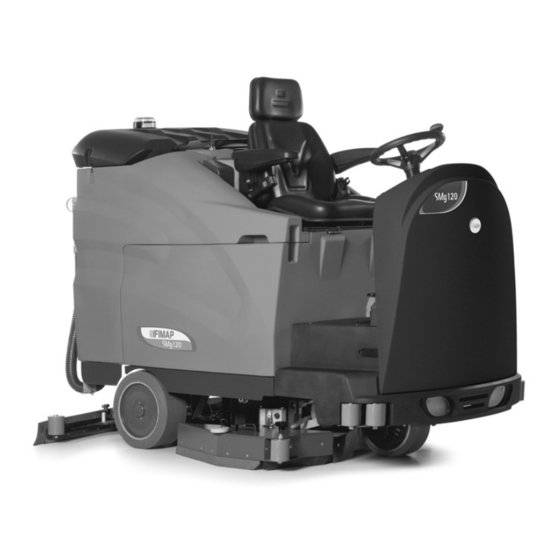
- Page 1 USE AND MAINTENANCE MANUAL SMG120 B ED. 03-2012 ORIGINAL INSTRUCTIONS Doc. 10034073 Ver.
- Page 2 The descriptions contained in this document are not binding. The company therefore reserves the right to make any modifications at any time to elements, details, or accessory supply, as considered necessary for reasons of improvement or manufacturing/commercial requirements. The reproduction, even partial, of the text and drawings contained in this document is prohibited by law.
-
Page 3: Table Of Contents
CONTENTS ON CONSIGNMENT OF THE MACHINE................................5 SERIAL NUMBER PLATE ....................................5 INTRODUCTORY COMMENT .................................... 5 INTENDED USE ........................................5 TECHNICAL DESCRIPTION....................................6 SYMBOLS USED ON THE MACHINE................................7 GENERAL SAFETY REGULATIONS................................10 MACHINE PREPARATION....................................11 1. HANDLING THE PACKAGED MACHINE............................11 2. - Page 4 43. BRUSH CLEANING.................................. 31 EXTRAORDINARY MAINTENANCE................................32 44. REPLACING THE FRONT SQUEEGEE RUBBER ........................... 32 45. REPLACING THE REAR SQUEEGEE RUBBER ..........................32 46. REPLACING THE REAR SPLASH GUARD RUBBER ON THE SIDE COVER OF THE BRUSH HEAD ............32 47.
-
Page 5: On Consignment Of The Machine
On consignment of the machine Serial number plate When the machine is delivered to the customer, an immediate check must be performed to ensure all the material mentioned in the shipping documents has been received, in addition to verifying that the machine has not been damaged during transportation. -
Page 6: Technical Description
TECHNICAL DESCRIPTION SMG120 B Working width 1200 Squeegee width 1266 Working capacity, up to 7920 Disc brush No. / ∅Ø mm 2 / 610 Disc brush rotations Brush motor 36/2000 Maximum pressure on the brushes Traction motor 24 / 1500 Traction wheel (diameter / width) ∅... -
Page 7: Symbols Used On The Machine
SYMBOLS USED ON THE MACHINE Main switch or key switch symbol Used on the instrument panel, to indicate the key switch for machine operation on (ON-I) or off (OFF-0) Symbol denoting acoustic alarm Used to indicate the acoustic alarm button Symbol denoting forwards and backwards speed selector Used on the instrument panel, to indicate the speed of the forwards or backwards movements of the machine Symbol denoting pressure applied to the brushes... - Page 8 SYMBOLS USED ON THE MACHINE Symbol denoting recovery tank rotation Used on the instrument panel, for the green indicator light indicating rotation consent to recovery tank Symbol denoting water and detergent level adjustment Used on the left side of the control panel, to indicate the knobs for adjusting the percentage level of detergent dissolved in the water, and the level of water distributed on the brushes Symbol denoting the command to open or close the recovery tank and the suction cap Used on the steering column to indicate the command which allows the recovery tank and the suction cap to be opened or...
- Page 9 SYMBOLS USED ON THE MACHINE Symbol indicating the position of the solution tank drain pipe Symbol indicating the position of the recovery tank drain pipe Indicates the maximum gradient Label with instructions for using standard or concentrated detergents Label with warnings relating to the type of detergent to use Label with the pH value of the detergent to use Label relating to uncoupling the seat support Displayed on the seat support to indicate the uncoupling handle...
-
Page 10: General Safety Regulations
GENERAL SAFETY REGULATIONS The regulations below must be carefully followed in order to avoid harm to the operator and damage to the machine. WARNING: Read the labels on the machine carefully. Do not cover them for any reason and replace them immediately if they become damaged. •... -
Page 11: Machine Preparation
The machine is contained in specific packaging with a pallet for the handling with fork trucks. The packages cannot be placed on top of each other. The total weight of the machine and packaging is 680kg The dimensions of the packaging is as follows: SMG120 B A: 1620mm B : 1520 mm C : 2380 mm 1. -
Page 12: Steering Column Components
MACHINE PREPARATION 5. Level indicator for battery/hour meter 6. Red warning light indicating that there is a malfunction in the machine traction 7. Red indicator light, indicates that the parking brake is engaged or indicates the machine's braking system oil reserve level 8. -
Page 13: Footboard Components
MACHINE PREPARATION 17. Switch for opening and closing the suction cap and recovery tank rotation 5. FOOTBOARD COMPONENTS The components at the front right of the footboard are identified as follows: 18. Forward movement pedal 19. Backward movement pedal 20. Brake pedal 21. -
Page 14: Machine's Front Components
MACHINE PREPARATION 27. Solution tank drain pipe 28. Recovery tank drain pipe 29. Recovery tank discharge cap 30. Flashing warning light 31. Water/detergent solution filler cap 32. Rapid filling kit 8. MACHINE'S FRONT COMPONENTS The front components of the machine are identified as follows: 33. -
Page 15: Handling - Inserting Batteries
MACHINE PREPARATION WARNING: You are advised to always wear protective gloves, to avoid the risk of serious injury to your hands. WARNING: You are advised to only lift and move the batteries with lifting and transportation means suitable for the specific weight and size 11. -
Page 16: Battery Connection And Battery Connectors
MACHINE PREPARATION 11. Turn the key of the main switch a quarter of a turn clockwise (to position 1). 12. The recovery tank will begin to rotate when the switch (5) is moved downwards, open it to its maximum rotation. 13. -
Page 17: Battery Charge Level Indicator (Battery Version)
MACHINE PREPARATION To connect the battery charger you must: 1. Move the machine near to the battery charger 2. Make sure that the key switch in the “0” position 3. Engage the parking brake 4. Grip the seat rotation uncoupling handle (1), move it forward as far as it will go 5. -
Page 18: Working Forward Speed
MACHINE PREPARATION In case of lack of oil in the braking system, the red warning light (2) on the instrument panel will come on; contact the technician to check the level of brake oil. Press downwards on the pedal (3) and pull it towards the rear of the machine to engage the parking brake. 16. -
Page 19: Increasing The Pressure On The Brush Head Unit
MACHINE PREPARATION 18. INCREASING THE PRESSURE ON THE BRUSH HEAD UNIT This machine can increase the pressure on the brushes via the knob (1) located on the instrument panel; it has three different settings: Step01: the weight exerted on the floor is 110 kg. Step02: the weight exerted on the floor is 130 kg. -
Page 20: Regulating The Detergent
MACHINE PREPARATION WARNING: Always use detergents whose manufacturer's label indicates their suitability for scrubbing machines. Do not use acid or alkaline products or solvents without this indication. In addition, you are advised to always use low foam detergents. Do not use pure acids or detergents with a stronger gradation than that indicated on the label supplied. -
Page 21: Recovery Tank
MACHINE PREPARATION 22. RECOVERY TANK Make sure the recovery tank is empty, otherwise empty it completely. Check the cap of the drainage tube (1) (on the rear of the machine) is correctly closed. Check that the drain pipe cap (2) at the rear of the machine is correctly closed. 23. -
Page 22: Assembling The Brushes
MACHINE PREPARATION 26. ASSEMBLING THE BRUSHES To assemble the brushes of the brush head body, proceed as follows: 1. Check that the brush head body is lifted off the ground 2. Turn the main switch key anticlockwise to the "0" position 3. -
Page 23: Priming The Detergent Pump
MACHINE PREPARATION PRIMING THE DETERGENT PUMP The detergent pump must be primed before starting work; proceed as follows to do so: 1. Check that the main switch is in the “Off – 0” position 2. Check that the battery connector is disconnected from the machine connector 3. -
Page 24: Work
WORK 29. WORK Before beginning to work, it is necessary to: 1. make sure the recovery tank is empty, otherwise empty it completely 2. Check that the main switch (3) of the machine is set to "0" 3. connect the battery connector (1) to the electric system connector (2) 4. -
Page 25: Braking System Oil Level
WORK 10. Rotate the tap lever (7) in an anticlockwise direction, allowing for full passage of water. This lever should not be used to make adjustments. To obtain the correct dose to the brushes, use the knobs only to adjust the amount of water solution (8) and detergent (9). See paragraph “DETERGENT ADJUSTMENT WITH FSS SYSTEM”. -
Page 26: At The End Of The Work
AT THE END OF THE WORK 35. AT THE END OF WORK At the end of the work, and before carrying out any type of maintenance, perform the following operations: 1. Turn the water flow rate adjustment knob (1) to the zero position 2. -
Page 27: Daily Maintenance
DAILY MAINTENANCE PERFORM ALL MAINTENANCE OPERATIONS IN SEQUENCE 36. CLEANING THE SUCTION MOTOR FILTER 1. Check the recovery tank is empty (if necessary, empty it). 2. Check that the parking brake is engaged, and if not, engage it 3. Turn the key of the main switch (1) a quarter of a turn clockwise (to position 1). The green indicator light on the control panel indicating consent to the rotation of the suction cap is switched on. -
Page 28: Cleaning The Squeegee
DAILY MAINTENANCE 38. CLEANING THE SQUEEGEE The careful cleaning of the whole vacuum unit ensures better drying and cleaning of the floor as well as greater duration of the suction motor. Proceed as follows for cleaning: 1. Check that the parking brake is engaged, and if not, engage it 2. -
Page 29: Weekly Maintenance
WEEKLY MAINTENANCE 40. CLEANING THE SUCTION HOSE Whenever suction seems to be unsatisfactory, check that the suction tube is not obstructed. If necessary clean with a jet of water as follows: 1. Make sure the recovery tank is empty, otherwise empty it completely. 2. -
Page 30: Detergent Tank Cleaning
WEEKLY MAINTENANCE 5. Close the water tap (1) 6. Disconnect the solution tank drain hose (2) located at the rear of the machine 7. Unscrew the solution tank drain hose cap 1. Unscrew the solution tank filling plug (3), located behind the operator's seat 2. -
Page 31: Brush Cleaning
WEEKLY MAINTENANCE 43. BRUSH CLEANING Proceed as follows for cleaning: 1. Check that the parking brake is engaged, and if not, engage it 2. Check that the electrical system connector is disconnected from the battery connector, and if not, disconnect it 3. -
Page 32: Extraordinary Maintenance
EXTRAORDINARY MAINTENANCE 44. REPLACING THE FRONT SQUEEGEE RUBBER Suction will be poor and the machine will not dry perfectly if the front squeegee rubber is worn. Proceed as follows to replace: 1. Check that the parking brake is engaged, and if not, engage it 2. -
Page 33: Replacing The Front Splash Guard Rubber On The Side Cover Of The Brush Head
EXTRAORDINARY MAINTENANCE 4. Turn the knobs (1) in an anti-clockwise direction 5. Use the handle (2) to remove the right splash guard cover WARNING: This operation must be carried out using gloves to protect against contact with dangerous solutions. 6. Use suitable equipment to remove the rubber-pressing blade (3) from inside the side cover, and unscrew the screws (4) which fasten it to the splash guard support. -
Page 34: Side Splash Guard Height Adjustment
EXTRAORDINARY MAINTENANCE 48. SIDE SPLASH GUARD HEIGHT ADJUSTMENT If the splash guard rubbers on the brush head side cover not are not positioned correctly in relation to the floor, these may not function properly (i.e. they may not conduct water to the squeegee correctly). The height of the splash guard rubbers must therefore be adjusted. - Page 35 EXTRAORDINARY MAINTENANCE 12. Connect the battery connector to the machine connector. 13. Turn the key of the main switch a quarter of a turn clockwise (to position 1). 14. Disengage the parking brake 15. Make sure that the work programme is set to "Work" (position C). 16.
-
Page 36: Troubleshooting
TROUBLESHOOTING 50. THE MACHINE DOES NOT START 1. Check that batteries are charged 2. Make sure the electric system connector is connected to the battery connector 3. Check the key switch is ON/I 51. INSUFFICIENT WATER ON THE BRUSHES 1. Check there is water in the solution tank 2. -
Page 37: Electric Fuses And Thermal Cut-Outs
With the dosing system out-of-use, the water flow is regulated via the tap on the steering column. Contact an Authorised FIMAP Retailer to have the system repaired. 59. ALARMS The machine is fitted with a flashing warning light (1) for diagnosing faults in the traction motor control system. -
Page 38: Disposal
DISPOSAL To dispose of the machine, take it to a demolition centre or an authorised collection centre. Before scrapping the machine it is necessary to remove and separate the following materials and send them to the appropriate collection centres in accordance with the environmental hygiene regulations currently in force: •... -
Page 39: Choosing And Using The Brushes
TABLE FOR CHOOSING THE BRUSHES Machine No. of brushes Code Type of bristles Length Notes ∅ Bristles ∅ Brush 404627 LIGHT BLUE BRUSH 405628 ABRASIVE BRUSH 405629 BLACK BRUSH SMG120 B 405630 WHITE BRUSH 431990 LIGHT BLUE BRUSH 405519 PAD HOLDER... -
Page 40: Ec Declaration Of Conformity
37050 Santa Maria di Zevio (VR) - ITALY Santa Maria di Zevio, 08/03/2012 FIMAP S.p.A. Legal representative Giancarlo Ruffo FIMAP spa Via Invalidi del Lavoro, 1 - 37050 S.Maria di Zevio (Verona) Italy Tel. +39 045 6060411 r.a. - Fax +39 045 6060417 - E-mail:fimap@fimap.com - www.fimap.com...
Need help?
Do you have a question about the SMG120 B and is the answer not in the manual?
Questions and answers