
Related Manuals for ARIS ExTensor


Summary of Contents for ARIS ExTensor
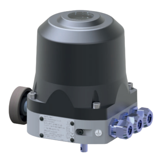
- Page 1 Stellantriebe Original declaration of incorporation with manual for ARIS Actuator ExTensor Actuator for potentially explosive atmospheres of zone 1 Note: Picture shows actuator with options...
-
Page 2: Table Of Contents
Tabel of content 1. Identification ................................3 1.1 Approvals / Labeling ..........................................3 1.2 Nameplate / Labeling ........................................... 3 1.3 Guidelines and standards ........................................4 2. Safety information ..............................4 2.1 Warnings .............................................. 4 2.2 General safety advice..........................................5 3. Technical specification ..............................5 3.1 Functions and application areas (Intended use) .................................. -
Page 3: Identification
This manual is valid for: Description: Electrical actuator for potentially explosive atmospheres ATEX / IECEx Type: ExTensor (and add-ons/options) Further details see chapter 1.2 nameplate / labeling Approvals / Labeling ATEX (Gas) II 2 G Ex db IIC T6 Gb ATEX (Dust) II 2 D Ex tb IIIC T80°C Db... -
Page 4: Guidelines And Standards
Guidelines and standards Aris actuators of the ExTensor series are partly completed machinery in the sense of the European Directive 2006/42/EC. The Decla ration of Incorporation for the devices can be found at the end of this operating manual. During the development, production and... -
Page 5: General Safety Advice
Functions and application areas (Intended use) ARIS actuators of the ExTensor series are designed exclusively for industrial use in potentially explosive areas according to their labeling. They are used to actuate control and shut-off devices ( aps, valves, taps, sliders, dosing pumps, etc.). -
Page 6: Housing Entries (Tapped Holes)
Housing entries (tapped holes) 3.2.1 Cable and wire entries Features ARIS ExTensor 3x M25x1.5 tapped holes When delivered, the actuators are provided with a transport protection (protective sticker), which covers the threaded holes of the cable and line entries. This must be removed and replaced with suitable, approved entries or plugs. The entries/blind plugs used must correspond to the ignition protection types of the drive. -
Page 7: Performance Data
- The ATEX/IECEx approval of the device becomes void in the event of non-compliance or misuse. Suitable products (cable entries, blind plugs) are available as accessories from ARIS, tailored to the ATEX/IECEx products. If requi- red, these are loosely enclosed with the drive. The delivery is always unassembled. -
Page 8: Dimensions
ExTensor Model "S" Dimensions (Primary model) Bohrung 50x65 4x M6x10 77,5 3x M25x1,5 Welle ISO Innenvierkant Wellen Passfeder T=2,5 Wellen Querbohrung ExTensor... - Page 9 ExTensor Model "M" (Secondary model) Bohrung 50x65 4x M6x10 36 36 3x M25x1,5 Welle Welle Welle ISO (5211) Passfeder Querbohrung Innenvierkant ExTensor...
- Page 10 ExTensor Model"L" (Secondary model) 77,5 3x M25x1,5 Welle Querbohrung Welle Passfeder ISO-Welle Vierkantmaße Drehmoment Maß A Maß B 80-150 150-180 Welle Querbohrung Drehmoment Maß ØX Maß ØY 80-150 ØJ 150-180 Wellen Passfeder Welle ISO (5211) Drehmoment Maß ØJ Maß K Maß L Maß T...
- Page 11 ExTensor Model "XL" (Secondary model) 36 36 3x M25x1,5 Passfeder DIN 6885-A 10x8x50 Welle ISO (5211) Innenvierkant ExTensor...
-
Page 12: Actuator Setup For Utilization
Actions must be taken to avoid the formation of condensation (e.g. in the event of temperature uctuations) Packaging ARIS drives are protected by special cardboard packaging for transport from the factory. Unpacking in the Ex area is not permitted as the materials could become electrostatically charged. -
Page 13: Information About Coatings
(e.g. by dropping it);no ropes, hooks, etc. attach directly to the drive • permanent overloading and blocking of the drive leads to damage to the drive • only use original ARIS spare parts Consider prior to attachment of couplings: • Do not turn actuator shafts by force;... -
Page 14: Initial Operation
This can be avoided by loosening a cable/line entry or blind plug so that air can ow through it. CAUTION DANGER! The lead-in must be professionally closed again before commissioning or for further storage. Danger! Pressure proof encapsulation ExTensor... -
Page 15: Electrical Connection
To create the type of protection, ameproof gaps with narrow cylindrical ts are installed. Gap surfaces must not be damaged. Damaged surfaces must not be machined or repaired in any other way - contact ARIS Service. Cover and housing parts must be handled with care. - Page 16 In doing so, observe the procedure and instructions for opening and connecting the drive in these operating instructions. De-energize the drive before opening. Make sure that there is no explosive atmosphere in the area when working on the drive. Also, before performing a reset, make sure that the causes of the elevated temperature have been eliminated. ExTensor...
- Page 17 Phase / Supply 85 ... 265 V AC Control connection > left-turning (CCW) Control connection > right-turning (CW) Ground wire inside of the housing. Connection 24 V DC – Connection 19.2…28.8 V DC Control connection > left-turning (CCW) Control connection > right-turning (CW) ExTensor...
-
Page 18: Actuator Operation Without Modules (Standard)
The functionality of the buttons is explained in section "Operating modes". 6.1.2 Operating modes The different operating modes of the actuator can be selected via the slide switch resp. the MENU button. The actual operating mode is shown on the display. ExTensor... - Page 19 The actuator may run and move the connected valve when switching from MANU to AUTO and you con rm the warning message. WARNING After switching from MANU to AUTO and con rming the warning message the actuator can be operated by using the buttons "L" & "R". ExTensor...
- Page 20 Selection of input signal for driving the actuator Signal OUT Selection of output signal for position feedback Wire monitor Setting of actuator behaviour in case of cable breakage (formerly wire break monitoring) Status info Activate/Deactivate message output Offset Settings for allowed control deviation in controller mode ExTensor...
- Page 21 If the login is missing, only the INFO MENU and the menu item LOGIN (in MAIN MENU) are visible. The following users are selectable: • User • Service • Manufacturer (ARIS only) A logged in user can be logged out via the menu item "Logout". ExTensor...
- Page 22 Left and right end positions can be interchanged. The assignment of the turning direction of the inputs 2/3 and the buttons LI/RE do not change. The end positions must be 28° apart due to technical reasons. If the difference range is too small, the actuator will prompt "Error Code 51". ExTensor...
- Page 23 NOTICE: Defaults for the set value of the end positions must cover min. 20% of the total range, otherwise "Error Code 80" will be displayed. Example: Signal range 4 mA => Coverage 4 mA x 20% = 0.8 mA Lower end position 0.1 mA => Upper end position min. 0.9 mA (= 0.1mA + 0.8 mA) ExTensor...
- Page 24 Amount of relays: 2 (optional 4) Relays type: Bi-stable relay Switching voltage: max. 250 V AC / 125 V DC Allowed continuous current/channel: max. 2 A (at 230 V AC / 30 V DC); max. 0.2 A (at 125 V DC) ExTensor...
- Page 25 Settable only on relays no. 3 & 4! [1] Off Relay switching state 1 (switched on/active) 0 (switched off/inactive) left right end position end position [2] Sw.pt.high Relay switching state 1 (switched on/active) 0 (switched off/inactive) left right end position end position ExTensor...
- Page 26 [5] Cam low Relay switching state 1 (switched on/active) 0 (switched off/inactive) left right end position end position [6] Bl.det.le Relay switching state Blockade at left end position 1 (switched on/active) 0 (switched off/inactive) left right end position end position ExTensor...
- Page 27 The input signal type must additionally be set up with the onboard DIP switch, according to the desired signal type. DIP switch 1 and DIP switch 2 must not be active (On) simultaneous! DIP switch 4 and DIP switch 5 must not be active (On) simultaneous! ExTensor...
- Page 28 Potentiometer input When driving the actuator via a connected potentiometer, an auxiliary voltage of 5 V DC is generated over terminal 53 for poti supply. An additional external voltage supply for the potentiometer is not necessary. Potentiometer input i-Act (AI-) ExTensor...
- Page 29 The position of DIP switches 1-3 is irrelevant to the output signal setting. Voltage output [V] Current output [mA] Voltage output Current output – – Potentiometer output Potentiometer output Potentiometer output Voltage source potential-free Voltage source grounded 5-24V 5-24V ExTensor...
- Page 30 The following events/conditions lead to an open contact: • Actuator in MANU mode • Detection of a control variance (when active) • Occurrence of an error Performance data of the message output Switching voltage: 250 V AC / 30 V DC Allowed continuous current: 3 A ExTensor...
- Page 31 The turn-on hysteresis has to be set higher than the shut-off hysteresis! If the hysteresis is set too low, the actuator may operate in an unwanted behaviour depending on the actuator type. In this case, the hysteresis must be increased. ExTensor...
- Page 32 RPM acc. Acceleration ramp Defines the time [ms] of the acceleration ramp of the actuator in AUTO mode. RPM red. Brake ramp Defines the time [ms] of the brake ramp of the actuator in AUTO mode. ExTensor...
- Page 33 ([mA] & [V]). ADVICE If you are interested in any additional feature, please contact the ARIS sales department and have the serial number of the mounted electronics ready (check INFO MENU "Serial-No."). POWR. MENU (Power menu)
- Page 34 Connected and recognized boards are marked with an asterisk (*) after the board name. Example with relay board: Board connected/recognized: > Relay* Board not connected/not recognized: > Relay ADVICE Add-on boards must only be mounted/dismounted when the electronics is de-energized! ExTensor...
- Page 35 The handwheel may only be used when the drive is de-energized (no voltage/no current). Danger! On the back of the drive, there is a blind plug to close the handwheel option for WARNING equipment variants without a handwheel. This may not be removed or altered. ExTensor...
-
Page 36: Options
- mechanichal poti, terminals ... ? Maintenance and service ARIS actuators of the ExTensor series have permanent lubrication and are basically maintenance-free. We recommend carrying out a function test and a visual inspection once a year. Repairs: No repairs or mechanical processing of any kind may be carried out on the gap surfaces of the ameproof gaps. In particular, the cover/housing gap surfaces must not be changed. -
Page 37: Declaration Of Incorporation
Rotter Viehtrift 9, D ‐ 53842 Troisdorf in sole responsibility that the product Designation: Electric actuator ExTensor and identical Series: to which this declaration refers, complies with the essential requirements of the following European directives by being in accordance with the specified harmonized standards: Dir 2014/34/EU (ATEX) EN IEC 60079‐0:2018 (IEC 60079‐0:2017, Ed. -
Page 38: Type Examination Certificate
Type examination certificate (t.b.d.) ExTensor... - Page 40 Subject to technical changes. ARIS Stellantriebe GmbH Tel.: +49 2241 25186-0 Rotter Viehtrift 9 Fax: +49 2241 25186-99 53842 Troisdorf / Germany aris@stellantriebe.de www.stellantriebe.de Stellantriebe...
Need help?
Do you have a question about the ExTensor and is the answer not in the manual?
Questions and answers