Table of Contents
Advertisement
Quick Links
Advertisement
Table of Contents

Related Manuals for ARIS SCU5


Summary of Contents for ARIS SCU5
- Page 1 SCU5: Controller Product and User Manual Firmware Version 3.6...
- Page 2 The information in this document is subject to change without any notice. Content subject to change without notice SCU5: Sensor and Web Guide Controller User Manual v 3.6| Page 1 Copyright © 2021 Roll-2-Roll Technologies LLC https://r2r.tech...
-
Page 3: Table Of Contents
Enable and disable the sensors Automatic/Manual Icon Servo Center Icon Jog-left/Jog-right Icon Guide Point Guide Point Indicator Content subject to change without notice SCU5: Sensor and Web Guide Controller User Manual v 3.6| Page 2 Copyright © 2021 Roll-2-Roll Technologies LLC https://r2r.tech +1-888-290-3215... - Page 4 Output Type Absolute Error Display Screen Power User Screen Actuator Setting Stroke Pitch Motor Polarity Content subject to change without notice SCU5: Sensor and Web Guide Controller User Manual v 3.6| Page 3 Copyright © 2021 Roll-2-Roll Technologies LLC https://r2r.tech +1-888-290-3215...
- Page 5 Sensor 1/Sensor 2 Coverage Quality Factor Registers Web guide status and fault registers Guide point percentage Content subject to change without notice SCU5: Sensor and Web Guide Controller User Manual v 3.6| Page 4 Copyright © 2021 Roll-2-Roll Technologies LLC https://r2r.tech +1-888-290-3215...
- Page 6 TECHNICAL SUPPORT AND SERVICE Contact information Return shipping instructions REVISION HISTORY Hardware Revision Firmware Revision Content subject to change without notice SCU5: Sensor and Web Guide Controller User Manual v 3.6| Page 5 Copyright © 2021 Roll-2-Roll Technologies LLC https://r2r.tech +1-888-290-3215...
-
Page 7: Introduction
INTRODUCTION This product manual provides information about installation, use and maintenance of SCU5 controller. The controller includes an operator interface that is used for both measurement and control applications within converting lines. For installation of the sensor and web guide please refer to the respective product manuals. -
Page 8: Web Position Sensor
Sensor and Web Guide Controller Specification The general specifications of the SCU5 controller are listed below. Depending on the application one of more of the output options would be available. -
Page 9: Controller Options
(PLC) or when set by remote controller (PLC) Content subject to change without notice SCU5: Sensor and Web Guide Controller User Manual v 3.6| Page 8 Copyright © 2021 Roll-2-Roll Technologies LLC https://r2r.tech... -
Page 10: Physical Dimensions Of Scu5
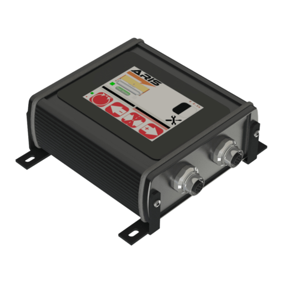
Fig. 2: SCU5 M Controller Physical Dimensions (All dimensions are in mm); Subject to change without notice. The SCU5 M controller has the following ports for connections to the sensor, motor driver and other devices. Fig. 3: SCU5 MD Connector Ports Content subject to change without notice SCU5: Sensor and Web Guide Controller User Manual v 3.6| Page 9... -
Page 11: Power Input (Port 1)
Power Input (Port 1) The SCU5 M operates under 24 VDC (± 5%) power with a maximum current requirement of 5 Amps. The power is supplied through a Switchcraft DC power connector. WARNING: Supplying more than 24 VDC would damage the controller permanently. -
Page 12: Motor Communication (Port 2)
Please consult with the factory before adding any patch cords. Motor Communication (Port 2) The SCU5 controller with “M” suffix includes a 4-pin Male M8 connector to connect the controller to a motor driver (supplied by Roll-2-Roll Technologies LLC) used for web guiding applications. A pre-wired motor communication cable with the 4-pin M8 female connectors on both ends is used to connect the controller and the motor driver. -
Page 13: Analog Output (Port 2)
Analog Output (Port 2) The SCU5 controller without the motor suffix will include a 3-pin Male M8 connector for analog output. The pinouts for the connector are shown below. Color Signal Brown Voltage Blue Current Black Ground/Common The outputs can be chosen via the touchscreen interface to any of the following available output options:... -
Page 14: Opto-Isolated Output (Port 3)
Opto-Isolated Output (Port 3) For some applications two opto-isolated outputs are available from the SCU5 controller. These outputs are available on a 4-pin M12 female pin connector. A standard M12 4-pin A coded male connector or a pre-wired M12 cable can be used for the connection. The pin functions for the connector are shown in the table below. -
Page 15: Safety Instructions
Be aware of all national, state, and local requirements for accident prevention and environmental protection. Proper Use The SCU5 M controller is intended for indoor use only for use in industrial and lab equipment that process materials in web form as they move through a converting or raw material manufacturing process. Improper Use ●... -
Page 16: Operation And Operator Interface
The web guiding operations are accomplished using the web guide operation buttons on the bottom of the screen. The capacitive touchscreen on the SCU5 controller uses a language independent icon based screen that allows ease of operation. Never use sharp or pointed tools of any kind to operate the interface. Best practice is to have operators use their fingers to press the different icons. -
Page 17: Web Detected Indicator
If both sensors are the same Content subject to change without notice SCU5: Sensor and Web Guide Controller User Manual v 3.6| Page 16 Copyright © 2021 Roll-2-Roll Technologies LLC https://r2r.tech... -
Page 18: Sensor Orientation Indicator
Enable both sensor 1 and sensor 2 ● Disable both sensor 1 and sensor 2 Content subject to change without notice SCU5: Sensor and Web Guide Controller User Manual v 3.6| Page 17 Copyright © 2021 Roll-2-Roll Technologies LLC https://r2r.tech +1-888-290-3215... -
Page 19: Automatic/Manual Icon
NOTE: This functionality has no meaning for sensing applications. However, some custom applications with custom firmware may use the functionality. Servo Center Icon Default/normal state Servo-centering ON Content subject to change without notice SCU5: Sensor and Web Guide Controller User Manual v 3.6| Page 18 Copyright © 2021 Roll-2-Roll Technologies LLC https://r2r.tech +1-888-290-3215... -
Page 20: Jog-Left/Jog-Right Icon
When the controller is in servo centering mode, the actuator connected to the SCU5 controller will move towards the home position or center position which is provided by the servo center sensor, typically an inductive proximity switch. -
Page 21: Guide Point
Content subject to change without notice SCU5: Sensor and Web Guide Controller User Manual v 3.6| Page 20 Copyright © 2021 Roll-2-Roll Technologies LLC https://r2r.tech +1-888-290-3215... -
Page 22: Fine Guide Point Adjustment
50% setting. Some of the changes might have no effect if the web guide is in an extreme position. Content subject to change without notice SCU5: Sensor and Web Guide Controller User Manual v 3.6| Page 21 Copyright © 2021 Roll-2-Roll Technologies LLC https://r2r.tech... -
Page 23: Reset Guide Point
(fully extended) of completely black (fully retracted). Content subject to change without notice SCU5: Sensor and Web Guide Controller User Manual v 3.6| Page 22 Copyright © 2021 Roll-2-Roll Technologies LLC https://r2r.tech... - Page 24 SCU5 controller and Roll-2-Roll Driver. WARNING: If the actuator connected to the SCU5 moves but the actuator position bar does not indicate any movement (either completely black or red), this might be due to corrupted electronic position of the actuator in the memory.
-
Page 25: Advanced Settings Menu
Advanced Settings Menu The SCU5 controller provides advanced settings both for the operator and the maintenance personnel. The advanced settings screen will allow operators, power users and maintenance technicians to adjust parameters to suit their measurement and web guiding needs. This screen can be accessed by pressing the Advanced Settings icon on the home screen. -
Page 26: Operator Settings Screen
NOTE: Each sensor can have its own independent thresholding mode. Content subject to change without notice SCU5: Sensor and Web Guide Controller User Manual v 3.6| Page 25 Copyright © 2021 Roll-2-Roll Technologies LLC https://r2r.tech... - Page 27 Content subject to change without notice SCU5: Sensor and Web Guide Controller User Manual v 3.6| Page 26 Copyright © 2021 Roll-2-Roll Technologies LLC https://r2r.tech +1-888-290-3215...
-
Page 28: Sensor Selection
The algorithm also helps with background suppression. The user can disable the automatic Content subject to change without notice SCU5: Sensor and Web Guide Controller User Manual v 3.6| Page 27 Copyright © 2021 Roll-2-Roll Technologies LLC https://r2r.tech... -
Page 29: Live Processed Image Preview
These include right edge of a color (or grayscale), edge created by two colors, the position of a line with a Content subject to change without notice SCU5: Sensor and Web Guide Controller User Manual v 3.6| Page 28 Copyright © 2021 Roll-2-Roll Technologies LLC https://r2r.tech... -
Page 30: Right Edge Of A Color
Right edge of a color (Teaching) Right edge of a color (Teaching Saved) Content subject to change without notice SCU5: Sensor and Web Guide Controller User Manual v 3.6| Page 29 Copyright © 2021 Roll-2-Roll Technologies LLC https://r2r.tech +1-888-290-3215... -
Page 31: Edge Created By Two Colors
Once the teaching is saved, the controller always pick the first occurrence of the color with a certain width while scanning from left to right Content subject to change without notice SCU5: Sensor and Web Guide Controller User Manual v 3.6| Page 30 Copyright © 2021 Roll-2-Roll Technologies LLC https://r2r.tech... -
Page 32: Left Edge Of A Color
This is because the leftmost edge cannot be outside the sensor Content subject to change without notice SCU5: Sensor and Web Guide Controller User Manual v 3.6| Page 31 Copyright © 2021 Roll-2-Roll Technologies LLC https://r2r.tech... -
Page 33: Operator Width Screen
NOTE: The minimum value for nominal width that can be set is 1 mm and the maximum value is 9750 mm. Content subject to change without notice SCU5: Sensor and Web Guide Controller User Manual v 3.6| Page 32 Copyright © 2021 Roll-2-Roll Technologies LLC https://r2r.tech... -
Page 34: Upper Limit
When the measured web width is more than the nominal web width then the width error is positive. With an appropriate output on the SCU5 controller a fault signal can be generated when the positive width error is more than the upper limit. If the error is equal to the upper limit, no fault signal would be generated. -
Page 35: Teaching
48 mm sensor a web width of 24 mm would have an analog output value of 5 V if the analog Content subject to change without notice SCU5: Sensor and Web Guide Controller User Manual v 3.6| Page 34 Copyright © 2021 Roll-2-Roll Technologies LLC https://r2r.tech... -
Page 36: Error
Access to the respective settings are available by clicking the respective icon. Content subject to change without notice SCU5: Sensor and Web Guide Controller User Manual v 3.6| Page 35 Copyright © 2021 Roll-2-Roll Technologies LLC https://r2r.tech +1-888-290-3215... -
Page 37: Actuator Setting
WARNING: Changes to these settings can have a significant effect for both sensing and guiding applications. Wrong settings can cause damage to the actuator, web guide or devices connected to the SCU5 controller. Hence only those well versed in the operation of the web guiding system or the measurement/sensing system should change these settings. -
Page 38: Pitch
WARNING: When the acceleration is set to 0% the actuator will not respond in the automatic mode. Content subject to change without notice SCU5: Sensor and Web Guide Controller User Manual v 3.6| Page 37 Copyright © 2021 Roll-2-Roll Technologies LLC https://r2r.tech... -
Page 39: Sensor Setting
Content subject to change without notice SCU5: Sensor and Web Guide Controller User Manual v 3.6| Page 38 Copyright © 2021 Roll-2-Roll Technologies LLC https://r2r.tech... -
Page 40: Sensor Position/Orientation Setting
Content subject to change without notice SCU5: Sensor and Web Guide Controller User Manual v 3.6| Page 39 Copyright © 2021 Roll-2-Roll Technologies LLC https://r2r.tech... -
Page 41: Controller Setting
Controller Setting When the SCU5 controller is used for web guiding purposes the controller settings such as gain, deadband, etc.can be set from this screen. Gain The gain setting needs to be changed based on the actuator lead screw and the mechanical advantage of the web guide structure. -
Page 42: Lock On Lost Edge
This position may not be the home/middle position for the actuator. Content subject to change without notice SCU5: Sensor and Web Guide Controller User Manual v 3.6| Page 41 Copyright © 2021 Roll-2-Roll Technologies LLC https://r2r.tech... -
Page 43: Limit Switches
The controller will automatically select the appropriate edge and by default will provide the single edge position through the output. Content subject to change without notice SCU5: Sensor and Web Guide Controller User Manual v 3.6| Page 42 Copyright © 2021 Roll-2-Roll Technologies LLC https://r2r.tech... -
Page 44: Analog Setup
DHCP If the DHCP is set to ON the SCU5 controller (client device) will get the IP address from a network server or a router. The IP address, and other network parameters, would be assigned dynamically and may change after a power cycle if the server or router initiates the change. -
Page 45: Ftp
NOTE: The DHCP can also be set using the IPConfig utility or other network software directly through the network. This setting would enable or disable the FTP server on the SCU5 controller. This is an advanced feature and should not be changed without consulting with the factory. -
Page 46: Mac Address
Module Type The type of the industrial ethernet module in the SCU5 controller will be printed over the network LED. The available fieldbus options are EtherNet/IP, PROFINET, EtherCAT and Modbus/TCP. If no module is available on the SCU5 controller then the module type would be None. -
Page 47: Remote Control And Monitoring
FMMU setting in the ECS file. The information provided is only for reference. Input 0x1100 8-bit Content subject to change without notice SCU5: Sensor and Web Guide Controller User Manual v 3.6| Page 46 Copyright © 2021 Roll-2-Roll Technologies LLC https://r2r.tech +1-888-290-3215... -
Page 48: Controller Output And Plc Input
Bit # Value Label Description No sensor 0: if a sensor is present Content subject to change without notice SCU5: Sensor and Web Guide Controller User Manual v 3.6| Page 47 Copyright © 2021 Roll-2-Roll Technologies LLC https://r2r.tech +1-888-290-3215... - Page 49 1: 768 WPS 48 (0.0635 mm) 2: 1774 WPS 221 (0.125 mm) 3: 896 WPS 112 (0.127 mm) Content subject to change without notice SCU5: Sensor and Web Guide Controller User Manual v 3.6| Page 48 Copyright © 2021 Roll-2-Roll Technologies LLC https://r2r.tech +1-888-290-3215...
-
Page 50: Sensor 1/Sensor 2 Left Edge
Note: While in contrast mode if the sensor sees no contrast then this value would equal to the number of pixels in the sensor. Content subject to change without notice SCU5: Sensor and Web Guide Controller User Manual v 3.6| Page 49 Copyright © 2021 Roll-2-Roll Technologies LLC https://r2r.tech... -
Page 51: Sensor 1/Sensor 2 Coverage
1 while the eight least significant bits correspond to the quality factor of sensor 2. Content subject to change without notice SCU5: Sensor and Web Guide Controller User Manual v 3.6| Page 50 Copyright © 2021 Roll-2-Roll Technologies LLC https://r2r.tech... -
Page 52: Web Guide Status And Fault Registers
0:if the web guide is not jogging left operation 1: if the web guide is jogging left Content subject to change without notice SCU5: Sensor and Web Guide Controller User Manual v 3.6| Page 51 Copyright © 2021 Roll-2-Roll Technologies LLC https://r2r.tech +1-888-290-3215... -
Page 53: Guide Point Percentage
Sensor 1 /Sensor 2 Web Width When the SCU5 controller is set to provide the width, these registers provide the width output from the controller. Registers 14 and 15 are combined to provide a 32-bit value. The most significant 16-bits are provided in register 14 and the least significant 16-bits are provided in register 15. - Page 54 Note: If the filter is enabled the output provided would be the filtered output. When the SCU5 controller is not set to provide width, then the registers provide the mean widths of the webs seen by each sensor. Register 14 will provide the mean width of the webs seen by sensor 1 and register 15 will provide the mean width of the webs seen by sensor 2.
-
Page 55: Controller Input And Plc Output
3: Analog output is enabled and the analog output corresponds to the left edge position. Content subject to change without notice SCU5: Sensor and Web Guide Controller User Manual v 3.6| Page 54 Copyright © 2021 Roll-2-Roll Technologies LLC https://r2r.tech... - Page 56 Content subject to change without notice SCU5: Sensor and Web Guide Controller User Manual v 3.6| Page 55 Copyright © 2021 Roll-2-Roll Technologies LLC https://r2r.tech...
-
Page 57: Sensor Brightness Command Register
So if the controller would ever be used for standalone operation make sure to rewrite the lower limit to 5 and the upper limit to 125. Content subject to change without notice SCU5: Sensor and Web Guide Controller User Manual v 3.6| Page 56 Copyright © 2021 Roll-2-Roll Technologies LLC https://r2r.tech... -
Page 58: Sensor 1/Sensor 2 Automatic Brightness Control (S1A And S2A)
This functionality may be useful for some advanced applications. Content subject to change without notice SCU5: Sensor and Web Guide Controller User Manual v 3.6| Page 57 Copyright © 2021 Roll-2-Roll Technologies LLC https://r2r.tech... -
Page 59: Web Guide Command Register
The extreme limit depends on the sensor resolution and sensor width. Content subject to change without notice SCU5: Sensor and Web Guide Controller User Manual v 3.6| Page 58 Copyright © 2021 Roll-2-Roll Technologies LLC https://r2r.tech... -
Page 60: Guide Point Offset Register
WARNING: Web Guiding System enabled by SCU5 controller is an automatic control device that may stop and start at any time without notice, especially when controlled remotely. Hence standard safeguards must be in place to prevent any kind of injury. -
Page 61: Actuator Speed Register
0 and 100 in the 7 least significant bits. If the 7th bit is low then the value written in the register is being ignored. Content subject to change without notice SCU5: Sensor and Web Guide Controller User Manual v 3.6| Page 60 Copyright © 2021 Roll-2-Roll Technologies LLC https://r2r.tech... -
Page 62: Commissioning
Please refer to the respective sensor and web guide manual for proper installation of the web guiding system. The following section describes the steps and conditions required for automatic operation with a SCU5 M web guide controller. -
Page 63: Center Guiding Application
There is no general maintenance required for the web guide controller. Please refer to the respective sensor and web guide manual for maintenance information. Content subject to change without notice SCU5: Sensor and Web Guide Controller User Manual v 3.6| Page 62 Copyright © 2021 Roll-2-Roll Technologies LLC https://r2r.tech... -
Page 64: Technical Support And Service
If returning the product, please follow the instructions on the RMA form for quick and efficient service. Content subject to change without notice SCU5: Sensor and Web Guide Controller User Manual v 3.6| Page 63 Copyright © 2021 Roll-2-Roll Technologies LLC https://r2r.tech... -
Page 65: Revision History
SCU5 Rev C Nov 2017 Robustness improvements SCU5 Rev D Dec 2018 Added Digital output option Content subject to change without notice SCU5: Sensor and Web Guide Controller User Manual v 3.6| Page 64 Copyright © 2021 Roll-2-Roll Technologies LLC https://r2r.tech +1-888-290-3215... -
Page 66: Firmware Revision
Nov 2021 Added support for Hilscher module 3.6c Nov 2021 Added support for ODC 768 Content subject to change without notice SCU5: Sensor and Web Guide Controller User Manual v 3.6| Page 65 Copyright © 2021 Roll-2-Roll Technologies LLC https://r2r.tech +1-888-290-3215... - Page 67 Roll-2-Roll Technologies LLC 1110 S Innovation Way Dr Stillwater, OK 74074 www.r2r-tech.com info@r2r-tech.com +1-(888)-290-3215 Content subject to change without notice SCU5: Sensor and Web Guide Controller User Manual v 3.6| Page 66 Copyright © 2021 Roll-2-Roll Technologies LLC https://r2r.tech +1-888-290-3215...
Need help?
Do you have a question about the SCU5 and is the answer not in the manual?
Questions and answers