Table of Contents
Advertisement
Quick Links
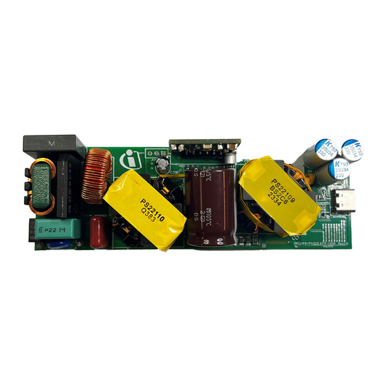
140 W HFB+PAG2S Solution Board
(REF_140W_HFB_PAG2S) user guide
About this document
Scope and purpose
This document provides information about the 140 W USB PD reference board using a EZ-PD™ CYPAS213 for
USB PD Extended Power Range (EPR) control, an XDPS2221 digital power controller for power factor correction
(PFC) with hybrid flyback (HFB), and a CoolGaN™ IGLD60R190D1 MOSFET as a main switch. The document
includes a quick start guide for EZ-PD™ CYPAS213 and XDPS2221 controller-based adapter solutions
(REF_140W_HFB_PAG2S).
Intended audience
This document is primarily intended for anyone using the 140 W PFC+ HFB USB PD + synchronous-rectification
(SR) high-power density charger adapter solution with highly integrated Infineon XDP™ and EZ-PD™ devices.
User guide
Please read the sections "Important notice" and "Warnings" at the end of this document
002-38685 Rev. *A
www.infineon.com
2024-01-29
Advertisement
Table of Contents

Related Manuals for Infineon REF 140W HFB PAG2S


Summary of Contents for Infineon REF 140W HFB PAG2S
-
Page 1: About This Document
Intended audience This document is primarily intended for anyone using the 140 W PFC+ HFB USB PD + synchronous-rectification (SR) high-power density charger adapter solution with highly integrated Infineon XDP™ and EZ-PD™ devices. User guide Please read the sections “Important notice” and “Warnings” at the end of this document 002-38685 Rev. -
Page 2: Important Notice
Boards provided by Infineon Technologies. The design of the Evaluation Boards and Reference Boards has been tested by Infineon Technologies only as described in this document. The design is not qualified in terms of safety requirements, manufacturing and operation over the entire operating temperature range or lifetime. -
Page 3: Safety Precautions
140 W HFB+PAG2S Solution Board (REF_140W_HFB_PAG2S) user guide Safety precautions Safety precautions Note: Please note the following warnings regarding the hazards associated with development systems. Table 1 Safety precautions Warning: The DC link potential of this board is up to 1000 VDC. When measuring voltage waveforms by oscilloscope, high voltage differential probes must be used. -
Page 4: Table Of Contents
140 W HFB+PAG2S Solution Board (REF_140W_HFB_PAG2S) user guide Table of contents Table of contents About this document ........................1 Important notice ..........................2 Safety precautions .......................... 3 Table of contents ..........................4 Introduction .......................... 5 Specification ......................... 7 Board overview ........................8 Procedure to program EZ-PD™... -
Page 5: Introduction
Figure 1 High-level block diagram of a USB PD adapter Infineon’s XDPS2221 solution offers a PFC and HFB combo design that enables high power density designs and system efficiency, meeting international regulatory standards on power efficiency (such as EU CoC Version 5 Tier 2 and DoE Level VI), as well as an effective control of the adaptive wide output voltage range for the latest USB PD EPR standard V3.1. - Page 6 N-channel 40 V 19 A (Ta), 40 A (Tc) - Surface mount Infineon Technologies BSZ018N04LS PG-TDSON-8 FL Q100, 600 V CoolGaN™ enhancement- Q300, mode power transistor/ Infineon Technologies IGLD60R190D1 CoolGaN™ Q301 PG-LSON-8-1 Q400, OptiMOS™ 5 power-transistor, Infineon Technologies BSC070N10NS5 OptiMOS™ Q401 100 V...
-
Page 7: Specification
140 W HFB+PAG2S Solution Board (REF_140W_HFB_PAG2S) user guide Specification Specification Table 3 Test specifications Parameter Symbol Conditions Min Typ Unit Input voltage Vin(limit) Operating voltage 115/230 Input frequency Freq 50/60 Inrush current 264 Vac cold start INRUSH Input current Vin = 100 Vac 2000 Total power output Pout... -
Page 8: Board Overview
140 W HFB+PAG2S Solution Board (REF_140W_HFB_PAG2S) user guide Board overview Board overview The EZ-PD™ CYPAS213 + XDPS2221-based EPR 140 W USB PD charger and adapter solution (REF_140W_HFB_PAG2S) is designed to meet the specifications as shown in Table Figure 2 shows the schematic diagram for the XDPS2221 PFC hybrid flyback in the converter stage and the EZ-PD™... - Page 9 140 W HFB+PAG2S Solution Board (REF_140W_HFB_PAG2S) user guide Board overview Figure 2 Schematic diagram of EZ-PD™ PAG2S + XDPS2221-based design User guide 002-38685 Rev. *A 2024-01-29...
- Page 10 140 W HFB+PAG2S Solution Board (REF_140W_HFB_PAG2S) user guide Board overview The waveform shown in Figure 3 illustrates the constant voltage (CV) and constant current (CC) modes of performance of the 140 W USB-C PD converter. This solution attains a power factor exceeding 0.9 for the entire input voltage range at a 140 W load while surpassing 0.98 for an input voltage of 115 Vac and a 140 W load.
-
Page 11: Procedure To Program Ez-Pd™ Cypas213-Based Board
140 W HFB+PAG2S Solution Board (REF_140W_HFB_PAG2S) user guide Procedure to program EZ-PD™ CYPAS213-based board Procedure to program EZ-PD™ CYPAS213-based board EZ-PD™ PAG2S supports the PSoC™ MiniProg4 (CY8CKIT-005) as a programmer to program the EZ-PD™ controllers. The EZ-PD™ CYPAS213-based main board can be programmed using a PSoC™ MiniProg4 five-pin connection. -
Page 12: Using The Cy4532 Ez-Pd™ Program And Evaluation Kit
140 W HFB+PAG2S Solution Board (REF_140W_HFB_PAG2S) user guide Procedure to program EZ-PD™ CYPAS213-based board After successful toggling between the PAG2S IC and programmer, the “Connected” message is shown at the bottom right of the window. 5. Click Program after you see the “Connected” message. If the program is successful, a “Successfully programmed”... -
Page 13: Dp Vision Programming Interface And Settings
140 W HFB+PAG2S Solution Board (REF_140W_HFB_PAG2S) user guide Procedure to program EZ-PD™ CYPAS213-based board .dP vision programming interface and settings To communicate with the control IC and burn the configurable parameters, the .dp interface board Gen 2 is required. The interface board requires firmware version 2.5 (dpIfGen2_V2.5.0_2017_6_27) or later to establish communication with the control IC XDPS2221. -
Page 14: Test Setup
140 W HFB+PAG2S Solution Board (REF_140W_HFB_PAG2S) user guide Test setup Test setup Figure 9 shows the optimal test setup to capture the electrical data of the DUT and calculate the efficiency. The setup captures the following data: Input power using a power meter •... - Page 15 140 W HFB+PAG2S Solution Board (REF_140W_HFB_PAG2S) user guide Test setup AVS: 15.0 V-28.0 V 140 W • Choose a suitable pre-configured PDO or configure a new one using the EZ-PD™ Configuration Utility. Figure 10 USB-C PD POWER-Z tester User guide 002-38685 Rev.
-
Page 16: Quick Steps To Demo
140 W HFB+PAG2S Solution Board (REF_140W_HFB_PAG2S) user guide Quick steps to demo Quick steps to demo The following are the quick steps to set up and start the 140 W EPR USB PD Solution Board. This test uses pre-configured PDOs. 1. -
Page 17: References
140 W HFB+PAG2S Solution Board (REF_140W_HFB_PAG2S) user guide References References Datasheets [1] EZ-PD™ PAG2S, SR + USB-C PD IC XDPS2221 PFC + Hybrid-Flyback combo IC CoolGaN™ IGLD60R190D1 600V CoolGaN™ enhancement-mode Power Transistor User guide 002-38685 Rev. *A 2024-01-29... -
Page 18: Revision History
140 W HFB+PAG2S Solution Board (REF_140W_HFB_PAG2S) user guide Revision history Revision history Document Date Description of changes revision 2023-10-06 Initial release. 2024-01-29 Updated user guide title and programming method. User guide 002-38685 Rev. *A 2024-01-29... -
Page 19: Disclaimer
For information on the types in question please contact your nearest Published by Infineon Technologies office. Except as otherwise explicitly approved by Infineon Infineon Technologies AG Technologies in a written document signed by 81726 Munich, Germany authorized...
Need help?
Do you have a question about the REF 140W HFB PAG2S and is the answer not in the manual?
Questions and answers