Table of Contents
Advertisement
Quick Links
KIT_PSC3M5_2GO PSOC
Control C3M5 compact kit
™
guide
About this document
Scope and purpose
This document provides a comprehensive understanding of the KIT_PSC3M5_2GO PSOC
Control C3M5
™
Compact Kit, which includes kit operation, an out-of-the-box (OOB) example and its operation, and the
hardware details of the board.
Intended audience
This document is intended for all embedded developers using the KIT_PSC3M5_2GO PSOC
Control C3M5
™
Compact Kit.
User guide
Please read the sections "Important notice" and "Warnings" at the end of this document
002-39956 Rev. **
www.infineon.com
2025-04-28
Advertisement
Table of Contents

Related Manuals for Infineon PSOC KIT PSC3M5 2GO


Summary of Contents for Infineon PSOC KIT PSC3M5 2GO
-
Page 1: About This Document
Intended audience This document is intended for all embedded developers using the KIT_PSC3M5_2GO PSOC Control C3M5 ™ Compact Kit. User guide Please read the sections "Important notice" and "Warnings" at the end of this document 002-39956 Rev. ** www.infineon.com 2025-04-28... -
Page 2: Important Notice
Boards provided by Infineon Technologies. The design of the Evaluation Boards and Reference Boards has been tested by Infineon Technologies only as described in this document. The design is not qualified in terms of safety requirements, manufacturing and operation over the entire operating temperature range or lifetime. -
Page 3: Safety Precautions
KIT_PSC3M5_2GO PSOC Control C3M5 compact kit guide ™ Safety precautions Safety precautions Note: Please note the following warnings regarding the hazards associated with development systems. Table 1 Safety precautions Caution: The evaluation or reference board contains parts and assemblies sensitive to electrostatic discharge (ESD). -
Page 4: Table Of Contents
KIT_PSC3M5_2GO PSOC Control C3M5 compact kit guide ™ Table of contents Table of contents About this document ..............1 Important notice . -
Page 5: Introduction
Control C3M5 Compact Kit is designed with the PSOC C3M5 series MCU to run an ™ ™ on-the-go motor application using USB pluggable hardware and with Infineon's PSOC C3 family of devices. ™ The board contains a USB interface, a DC-DC converter, a PSOC controller, an XMC4200 on-board debugger, an ™... -
Page 6: Kit Contents
PSOC Control C3M5 MCU and create your own designs. These examples can ™ be accessed through the ModusToolbox Project Creator tool. Additionally, see Infineon code examples for ™ ModusToolbox software to access these examples ™ •... -
Page 7: Board Details
XMC4200 based programmer and debugger • PSOC Control C3 device ™ • Onboard BLDC motor • Infineon's Intelligent Power Module (IPM) with three-phase inverter integrated • User switch and reset switch • Potentiometer control • User LEDs • Power LED •... - Page 8 KIT_PSC3M5_2GO PSOC Control C3M5 compact kit guide ™ 1 Introduction Table 2 (continued) Peripheral details Sl No. KIT_PSC3M5_2GO blocks PSOC Control C3 device (PSC3M5FDS2LGQ1 - U1) ™ User LEDs (D7, D8) Power LED (D3) Debug LED (D9) Table 3 KIT_PSC3M5_2GO pinout details Port pin Primary onboard function Connection details...
- Page 9 KIT_PSC3M5_2GO PSOC Control C3M5 compact kit guide ™ 1 Introduction Table 3 (continued) KIT_PSC3M5_2GO pinout details Port pin Primary onboard function Connection details P8.0 GPIO P8.0 is connected to the J4 header. This pin supports slave select in SPI mode of operation. P8.1 GPIO P8.1 is connected to the J4 header.
-
Page 10: Technical Support
Active low reset signal to PSC3M5 device. The reset switch is used to manually reset the MCU. Technical support For assistance or product related queries, contact Infineon Support or post your queries on the Infineon Developer Community platform. Abbreviations and definitions... - Page 11 KIT_PSC3M5_2GO PSOC Control C3M5 compact kit guide ™ 1 Introduction Table 4 (continued) Abbreviation Definition Pulse width modulation PMSM Permanent magnet synchronous motor GPIO General purpose input/output Inter-integrated circuit UART Universal asynchronous receiver transmitter Serial peripheral interface CORDIC Coordinate rotation digital computer Intelligent power module Op-amp Operational amplifier...
-
Page 12: Kit Operation
The motor speed is determined by the potentiometer setting. If the potentiometer is set to ‘0’ (fully turned counterclockwise), the motor will not run. OOB: GUI-based operation Download and install ModusToolbox Motor Suite Setup for Windows from the Infineon Developer ™ Center or use the link ModusToolbox Motor Suite (minimum required version: 2.4.1) - Page 13 KIT_PSC3M5_2GO PSOC Control C3M5 compact kit guide ™ 2 Kit operation Figure 3 GUI: Open new project Go to PSOC Control C3M5 Compact Kit, select RFO, and click New Project to open the configurator ™ view Figure 4 GUI: Configurator view User guide 002-39956 Rev.
- Page 14 KIT_PSC3M5_2GO PSOC Control C3M5 compact kit guide ™ 2 Kit operation A green dot at the bottom right of the GUI windows indicates a successful connection to the kit. The configurator view provides the option to configure the static parameters Click Flash Firmware on the lower right side and then click on the Default option to reprogram the default firmware into the controller Click the Test Bench button to switch to the Test Bench view...
-
Page 15: Creating Project And Programming/Debugging Using Modustoolbox
KIT_PSC3M5_2GO PSOC Control C3M5 compact kit guide ™ 2 Kit operation Figure 6 Oscilloscope view Oscilloscope view can be used to visualize any global variable in the project. It allows up to 4 variables to be monitored simultaneously. Figure 6 shows the three motor phase currents reconstructed from single shunt DC link current measurements. - Page 16 KIT_PSC3M5_2GO PSOC Control C3M5 compact kit guide ™ 2 Kit operation Figure 7 Connect compact kit to PC via USB-A connector The debugger on this kit features the J-Link LITE with UART. The debug LED (green) is always ON if the USB is connected In the Eclipse IDE for ModusToolbox , import the desired code example (application) into a new...
- Page 17 KIT_PSC3M5_2GO PSOC Control C3M5 compact kit guide ™ 2 Kit operation Figure 9 Choose Board Support Package Select the application in the Select Application window and click Create Figure 10 Select application User guide 002-39956 Rev. ** 2025-04-28...
- Page 18 KIT_PSC3M5_2GO PSOC Control C3M5 compact kit guide ™ 2 Kit operation To build and program a PSOC Control C3M5 MCU application, follow these steps: ™ In the Project Explorer tab, select <App_Name> project In the Quick Panel tab, scroll to the Launches section and click the <App_Name> Program (J-Link) configuration Figure 11 Programming in ModusToolbox...
- Page 19 KIT_PSC3M5_2GO PSOC Control C3M5 compact kit guide ™ 2 Kit operation Figure 12 Debugging in ModusToolbox ™ For a detailed explanation on how to debug using ModusToolbox , see the 'Program and debug' section in the ™ Eclipse IDE for ModusToolbox user guide.
-
Page 20: Hardware
KIT_PSC3M5_2GO PSOC Control C3M5 compact kit guide ™ 3 Hardware Hardware The hardware section provides details about the design document and how every block in the hardware is designed. This section details each schematic block in the design. The user may have to rework the hardware in a few of the cases where provisions are given but components on the board are not populated by default. -
Page 21: Hardware Functional Description
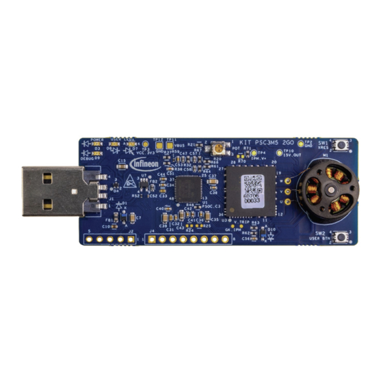
KIT_PSC3M5_2GO PSOC Control C3M5 compact kit guide ™ 3 Hardware Figure 14 Functional block diagram KIT_PSC3M5_2GO image Figure 15 KIT_PSCM5_2GO board top view Hardware functional description The PSOC Control C3M5 Compact Kit is designed as a plug-and-play device to demonstrate motor spinning ™... -
Page 22: Psoc C3M5 Mcu (Psc3M5Fds2Lgq1)
KIT_PSC3M5_2GO PSOC Control C3M5 compact kit guide ™ 3 Hardware 3.2.1 PSOC C3M5 MCU (PSC3M5FDS2LGQ1) ™ PSC3M5FDS2LGQ1 is a PSOC C3 family of devices with industrial power and motor applications. The ™ ® ® PSC3P5xD and PSC3M5xD devices are based on the Arm Cortex -M33 running up to 180 MHz with DSP and FPU capability. - Page 23 KIT_PSC3M5_2GO PSOC Control C3M5 compact kit guide ™ 3 Hardware Figure 17 PSOC Control C3M5 device power ™ Figure 18 PSOC Control C3M5 device decoupling capacitors ™ User guide 002-39956 Rev. ** 2025-04-28...
-
Page 24: Xmc4200 Based On-Board Programmer/Debugger
KIT_PSC3M5_2GO PSOC Control C3M5 compact kit guide ™ 3 Hardware 3.2.2 XMC4200 based on-board programmer/debugger XMC4200 is a member of the XMC4000 family, which incorporates a bridge between the USB interface and the PSOC Control C3M5 device. XMC4200 is a J-Link programmer and debugger on the board. The USB-SWD and ™... -
Page 25: Power Supply System
3.2.4.1 Voltage regulators and reverse voltage protection The linear regulator TLS208D1EJV33XUMA1 from Infineon is designed to generate a fixed 3.3 V output from VBUS. This LDO has internal protection for overcurrent (>800 mA), short circuit protection, and an overtemperature protection feature. -
Page 26: I/O Headers
KIT_PSC3M5_2GO PSOC Control C3M5 compact kit guide ™ 3 Hardware Figure 22 VBUS supply and 15V boost regulator 3.2.5 I/O headers A GPIO header on the kit allows the user to use interfaces such as UART, I2C, or SPI from external boards or sensors. -
Page 27: Ipm Motor Driver Module Operation
KIT_PSC3M5_2GO PSOC Control C3M5 compact kit guide ™ 3 Hardware Table 5 Pin assignment details UART P8.0 P8.1 MOSI P8.2 MISO P8.3 3.2.6 IPM motor driver module operation Intelligent Power Module IRSM83044 device is used on the board as an integrated power module for motor control applications. -
Page 28: Leds
KIT_PSC3M5_2GO PSOC Control C3M5 compact kit guide ™ 3 Hardware Note: Do not overstress the potentiometer while adjusting the motor speed. Over force applied on rotary control of potentiometer may cause permanent damage to the component. Figure 25 Potentiometer 3.2.8 LEDs Power LED The Power LED will glow once the board is powered using USB. -
Page 29: Reset And User Buttons
KIT_PSC3M5_2GO PSOC Control C3M5 compact kit guide ™ 3 Hardware Figure 27 Debug LED User LEDs The compact kit will have two user LEDs connected to free IOs. The user can utilize these LEDs for any indication purpose based on the user-specific application. Figure 28 User LEDs 3.2.9... - Page 30 KIT_PSC3M5_2GO PSOC Control C3M5 compact kit guide ™ 3 Hardware The user button (SW2) is provided for user application purpose. P4.6 from the PSOC C3 device is connected to ™ SW2. Default program loaded on the kit shall use SW2 for direction control of the motor while operating in standalone mode.
-
Page 31: Op_Amp For Single Shunt Foc
KIT_PSC3M5_2GO PSOC Control C3M5 compact kit guide ™ 3 Hardware Figure 30 Reset switch 3.2.10 OP_AMP for single shunt FOC Single Shunt FOC Operation Motor control application on this kit is based on a low-side single shunt current sensing method. A 1 Ω shunt resistor is connected on the LOW side FET of the IPM module. - Page 32 KIT_PSC3M5_2GO PSOC Control C3M5 compact kit guide ™ 3 Hardware Figure 31 Single Shunt FOC using external op-amp Pseudo differential mode Apart from the external op-amp, provision is given on the board for the pseudo differential mode of operation, which will isolate the op-amp circuitry. The shunt measurement is directly given to the two different ports of the PSOC control C3 device.
-
Page 33: Crystal Oscillators
KIT_PSC3M5_2GO PSOC Control C3M5 compact kit guide ™ 3 Hardware 3.2.11 Crystal oscillators A 12 MHz crystal is used as an external clock source for the XMC4200 on-board debugger. The XTAL1 and XTAL2 pins of the XMC4200 are connected to the external crystal operation. Figure 33 Crystal for XMC4200 on-board debugger ®... -
Page 34: Psoc ™ C3M5 Board Rework
KIT_PSC3M5_2GO PSOC Control C3M5 compact kit guide ™ 3 Hardware ® Figure 34 Cortex debug connector PSOC C3M5 Board rework ™ The PSOC Control C3M5 Compact Kit has the majority of the components assembled on the board for a ™ specific functionality. -
Page 35: Bill Of Materials
KIT_PSC3M5_2GO PSOC Control C3M5 compact kit guide ™ 3 Hardware ® Figure 35 Rework details for Cortex debug connector Bill of Materials Refer to the Printed Circuit Board Assembly Bill of Materials (PCBA BOM) file available on the kit webpage User guide 002-39956 Rev. -
Page 36: Revision History
KIT_PSC3M5_2GO PSOC Control C3M5 compact kit guide ™ Revision history Revision history Document version Date of release Description of changes 2025-04-28 Initial release User guide 002-39956 Rev. ** 2025-04-28... -
Page 37: Trademarks
Control C3M5 compact kit guide ™ Trademarks Trademarks PSOC , formerly known as PSoC , is a trademark of Infineon Technologies. Any references to PSoC in this ™ ™ ™ document or others shall be deemed to refer to PSOC ™... -
Page 38: Disclaimer
Infineon Technologies, Email: erratum@infineon.com Infineon Technologies’ products may not be used in any applications where a failure of the product or any consequences of the use thereof can reasonably be Document reference expected to result in personal injury.
Need help?
Do you have a question about the PSOC KIT PSC3M5 2GO and is the answer not in the manual?
Questions and answers