Table of Contents
Advertisement
Quick Links
AN170807
REF_BGT60LTR11AIP_M0
XENSIV™ 60 GHz radar reference board
Board version V 1.0
About this document
Scope and purpose
This application note describes the function, circuitry, and performance of the BGT60LTR11AIP M0 60 GHz radar
reference board (REF_BGT60LTR11AIP_M0). The board provides the supporting circuitry to the XENSIV™
BGT60LTR11AIP monolithic microwave integrated circuit (MMIC) with Antenna in Package (AIP).
This reference board offers a digital interface for configuration and transfer of the acquired radar data to an
Arm® Cortex®-M0 based microcontroller.
Intended audience
This document is intended for design engineers, technicians, and developers of electronic systems, working
with Infineon's XENSIV™ 60 GHz radar sensors.
Application note
Please read the sections "Important notice" and "Warnings" at the end of this document
Revision 1.10
www.infineon.com
2024-05-08
Advertisement
Table of Contents

Related Manuals for Infineon XENSIV REF-BGT60LTR11AIP-M0


Summary of Contents for Infineon XENSIV REF-BGT60LTR11AIP-M0
-
Page 1: About This Document
Arm® Cortex®-M0 based microcontroller. Intended audience This document is intended for design engineers, technicians, and developers of electronic systems, working with Infineon’s XENSIV™ 60 GHz radar sensors. Application note Please read the sections “Important notice” and “Warnings” at the end of this document Revision 1.10... -
Page 2: Table Of Contents
Detector hold time ..........................17 Operating frequency ..........................17 Pulse repetition time ..........................17 Running the radar algorithms ....................18 Infineon Developer Center ........................18 XMC™ Flasher ............................18 5.2.1 Reprogram the radar firmware ......................19 µC/Probe XMC™ tool ..........................22 Firmware description ...................... -
Page 3: Introduction
REF_BGT60LTR11AIP_M0 XENSIV™ 60 GHz radar reference board Introduction Introduction Overview The BGT60LTR11AIP MMIC is a fully integrated Antenna in Package (AIP) microwave motion sensor with built-in motion and direction of motion detectors. This small-sized radar solution is a compelling, smart, and cost- effective replacement for conventional passive infrared (PIR) sensors in low-power or battery-powered applications. -
Page 4: Key Features
REF_BGT60LTR11AIP_M0 XENSIV™ 60 GHz radar reference board Introduction Key features The BGT60LTR11AIP M0 reference board is optimized for initial product feature evaluation, fast prototyping design, and system integration. In addition, the sensor can be integrated into systems like laptops, tablets, TVs, and speakers to ‘wake’... -
Page 5: System Specifications
REF_BGT60LTR11AIP_M0 XENSIV™ 60 GHz radar reference board System specifications System specifications Table 1 BGT60LTR11AIP M0 reference board specifications Parameter Unit Min. Typ. Max. Comments System performance Maximum detection range – Typical motion detection range for human target at high sensitivity (in both E-plane and H-plane orientation) Power supply Supply voltage... -
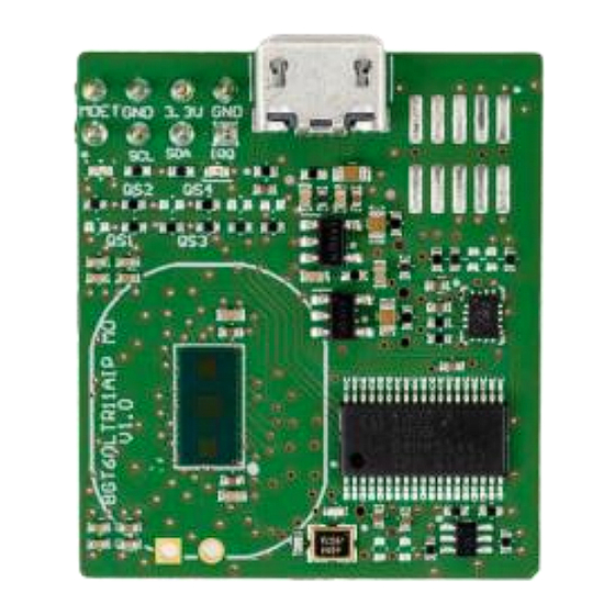
Page 6: Hardware Description
The BGT60LTR11AIP M0 reference board is a 26 x 28 mm PCB as shown in Figure 2. Mounted on top of the PCB is an Infineon XENSIV™ BGT60LTR11AIP 60 GHz radar sensor. The antennas are integrated into the chip package;... - Page 7 REF_BGT60LTR11AIP_M0 XENSIV™ 60 GHz radar reference board Hardware description 3.3 V 3.3 V 1.5 V 1.5 V 3.3 V IFIAi DIV_O DIV_O DIV_O SPI_MOSI IFIAo BGT_MOSI Level shifter BGT_MISO SPI_MISO hold BGT_SCK SPI_SCK IFQAi 1.5 V IFQAo RST_OUT BGT_RTSN hold XMC1302 1.5 V BGT60LTR11AIP...
-
Page 8: Bgt60Ltr11Aip Mmic
REF_BGT60LTR11AIP_M0 XENSIV™ 60 GHz radar reference board Hardware description BGT60LTR11AIP MMIC The BGT60LTR11AIP MMIC (Figure 4) is the main element on the BGT60LTR11AIP M0 reference board. The MMIC has one transmit antenna and one receive antenna integrated into the package, as shown in Figure The package dimensions are 6.7 mm x 3.3 mm x 0.56 mm, as shown in Figure... -
Page 9: Microcontroller Unit - Xmc1302
Top, side, and bottom views of BGT60LTR11AIP MMIC package (dimensions in mm) Microcontroller unit - XMC1302 The BGT60LTR11AIP M0 reference board uses an Arm® Cortex®-M0 microcontroller to allow flexibility to the users to do their own signal processing and algorithm implementation. Infineon’s XMC™ 32-bit industrial microcontroller (XMC1302-T038X0200) is designed for system cost and efficiency for demanding industrial applications. -
Page 10: Sensor Supply
REF_BGT60LTR11AIP_M0 XENSIV™ 60 GHz radar reference board Hardware description Sensor supply Because radar sensors are sensitive to supply voltage fluctuations or crosstalk between different supply domains, a low-noise power supply and properly decoupled supply rails are vital. Figure 7 shows the schematics of the low-pass filters employed to decouple the supplies of the different power rails in the BGT60LTR11AIP M0 reference board . -
Page 11: External Capacitors
REF_BGT60LTR11AIP_M0 XENSIV™ 60 GHz radar reference board Hardware description External capacitors The BGT60LTR11AIP MMIC is duty-cycled and performs a sample-and-hold (S/H) operation for lower power consumption. The S/H switches are integrated in the chip at each differential IQ mixer output port. They are controlled synchronously via the internal state machine. -
Page 12: Connectors
REF_BGT60LTR11AIP_M0 XENSIV™ 60 GHz radar reference board Hardware description A longer pulse width can have a higher value. This leads to a reduced bandwidth (BW) of the RC filter �� ℎ������ ). Consequently, there will be lower baseband noise because of reduced noise folding ��... -
Page 13: Leds
REF_BGT60LTR11AIP_M0 XENSIV™ 60 GHz radar reference board Hardware description Figure 11 Connectors on BGT60LTR11AIP M0 reference board, and their pinouts LEDs The board also has two LEDs (D1 and D2) as shown in Table 3 Figure Table 3 LEDs on BGT60LTR11AIP M0 reference board Purpose Green user LED connected to I/O P1.2 of the XMC1302 MCU. - Page 14 REF_BGT60LTR11AIP_M0 XENSIV™ 60 GHz radar reference board Hardware description 3.3V_PW 1.5V_PW SN74AVC4T245RSVR 1OE_N VCCA 100nF 2OE_N VCCB 100nF 1DIR 2DIR SPI_MISO BGT_MISO_1.5_A BGT_DIV_TRG_IN SPI_SCK BGT_SCK_1.5_A SPI_MOSI BGT_MOSI_1.5_A 1.5V_PW Figure 13 Connections of level shifter 1DIR - L -> B TO A (DIV_O, MISO) 2DIR - H ->...
-
Page 15: Mmic Quad State Inputs
REF_BGT60LTR11AIP_M0 XENSIV™ 60 GHz radar reference board Hardware description 3.10 MMIC quad state inputs The radar MMIC can be configured in both operation modes. In autonomous mode, the sensor configuration parameters are set via QS pins and external resistors. In SPI mode, the connection to a microcontroller allows setting the sensor configuration parameters by writing in the internal registers through SPI. -
Page 16: Layer Stackup And Routing
REF_BGT60LTR11AIP_M0 XENSIV™ 60 GHz radar reference board Hardware description 3.11 Layer stackup and routing The PCB is designed with a 4-layer stack up with standard FR4 material. Figure 15 shows the different layers and their respective thicknesses. Figure 15 QS1 to QS4 schematic and layout connections In the routing on the PCB, the VTUNE pin on BGT60LTR11AIP MMIC should be left floating. -
Page 17: Radar Mmic Settings
REF_BGT60LTR11AIP_M0 XENSIV™ 60 GHz radar reference board Radar MMIC settings Radar MMIC settings In SPI mode, the radar sensor MMIC configuration parameters are initially set via the QS pins and external resistors. The FW running on the microcontroller allows overwriting or setting the sensor configuration parameters by writing to the internal registers through SPI. -
Page 18: Running The Radar Algorithms
Before using this reference board and running the available algorithms, you should download the supporting software from Infineon. Infineon Developer Center To install and use Infineon plugins and tools, and use the full functionality of the 60 GHz radar, you must first download and install the Infineon developer Center (IDC) Launcher. -
Page 19: Reprogram The Radar Firmware
5.2.1 Reprogram the radar firmware Use (*.hex) binary with the XMC™ Flasher tool to reprogram the radar firmware: Start the XMC™ Flasher tool in Infineon Developer Center. Figure 18 Start XMC™ Flasher tool via Infineon Developer Center Click Connect, and then select the device name as “XMC1302-0200”. Click Ok. - Page 20 REF_BGT60LTR11AIP_M0 XENSIV™ 60 GHz radar reference board Running the radar algorithms Figure 19 XMC™ Flasher device selection and connection Note: Ensure that SEGGER J-Link drivers are installed before using the XMC™ Flasher tool. Otherwise, the default debugger type under XMC™ Flasher Target Interface Setup will be set to DAP, as shown in Figure 20a.
- Page 21 REF_BGT60LTR11AIP_M0 XENSIV™ 60 GHz radar reference board Running the radar algorithms Figure 21 Binary image file selection Navigate to the Binary folder and select the (*.hex) file (REF_BGT60LTR11AIP_M0_FW.hex), and then click Open. Figure 22 Binary image programming Click Program. The SEGGER progress window is displayed, showing the status of the flash operation. If programming succeeds, the message Programming &...
-
Page 22: Μc/Probe Xmc™ Tool
XMC™ kits. The latest version of µC/Probe XMC™ v4.3.0.9 is available for download from the Infineon website. Note: The BGT60LTR11AIP M0 reference board is supported only by the Micrium-based GUI tool. To run this Micrium-based GUI project: Go to the /Firmware_Software/GUI folder inside the locally installed package. - Page 23 REF_BGT60LTR11AIP_M0 XENSIV™ 60 GHz radar reference board Running the radar algorithms Figure 24 Run REF_BGT60LTR11AIP_M0_GUI The GUI interface shown in Figure 25 should appear. Apply Settings Button Raw I&Q FFT Peak data Algorithm Settings Advanced Motion Sensing Algorithm Settings FFT Peak Algorithm Detection Indicator (cannot mitigate Spectrum...
-
Page 24: Firmware Description
Arm® Cortex®-M processors and can be used to configure MCU peripherals (ADC, DMA, CCU4…). This reduces the development time and allows for quick porting of the firmware across XMC™ series MCUs. You need to install DAVE™ v4.4.2 or higher from the Infineon Developer Center (IDC). Firmware project overview The radar firmware is a ready-to-run DAVE™4 project, where the source files are generated based on the DAVE™... -
Page 25: Footprint
REF_BGT60LTR11AIP_M0 XENSIV™ 60 GHz radar reference board Firmware description Footprint The following sections provide the memory requirements for all the firmware modules, including device drivers, algorithms, and main radar applications. This helps in estimating the fixed and customizable memory requirements if a module or feature is removed or added. The footprint data is provided for the following environments: Board –... -
Page 26: Firmware Customization And Configuration
REF_BGT60LTR11AIP_M0 XENSIV™ 60 GHz radar reference board Firmware description Firmware customization and configuration The configuration files allow for customizing the drivers (config.h) and algorithms (algo_fft_peak.h/algo_advanced_motion_sensing.h) for the radar application. The following parameters can be configured by modifying the values of the related define statements, as described in Table Table 7 Define statements used for radar firmware configuration... -
Page 27: Simulation Results
REF_BGT60LTR11AIP_M0 XENSIV™ 60 GHz radar reference board Simulation results Simulation results To analyze the sensor radiation characteristics, the radiation pattern of the BGT60LTR11AIP M0 reference board is simulated along the H-plane and E-plane of the sensor. Figure 28 E-plane and H-plane orientations of BGT60LTR11AIP M0 reference board The realized gain of the transmitting antenna in H-plane and E-plane at a frequency of 61 GHz is shown in Figure 29a. -
Page 28: Measurement Results
REF_BGT60LTR11AIP_M0 XENSIV™ 60 GHz radar reference board Measurement results Measurement results Both the FFT peak and AMS algorithms process the I&Q raw data in parallel in the time domain, and both algorithms display the detection status simultaneously. Attention: The interference mitigation feature is applicable only to the AMS algorithm. FFT peak algorithm Scenario •... - Page 29 REF_BGT60LTR11AIP_M0 XENSIV™ 60 GHz radar reference board Measurement results Figure 31 Detection area of Advanced Motion Sensing algorithm Application note Revision 1.10 2024-05-08...
-
Page 30: References
REF_BGT60LTR11AIP_M0 XENSIV™ 60 GHz radar reference board References References Infineon Technologies AG. BGT60LTR11AIP MMIC datasheet; Available online Infineon Technologies AG. AN625: User's guide to BGT60LTR11AIP; Available online Application note Revision 1.10 2024-05-08... -
Page 31: Revision History
REF_BGT60LTR11AIP_M0 XENSIV™ 60 GHz radar reference board Revision history Revision history Document Date Description of changes revision 1.00 2023-02-14 Initial release 1.10 2024-05-08 Added AMS algorithm library footprint under section Application note Revision 1.10 2024-05-08... -
Page 32: Disclaimer
Infineon Technologies hereby Infineon Technologies’ products may not be used in disclaims any and all warranties and liabilities of any applications where a failure of the product or any any kind (including without limitation warranties of © 2024 Infineon Technologies AG.
Need help?
Do you have a question about the XENSIV REF-BGT60LTR11AIP-M0 and is the answer not in the manual?
Questions and answers