Table of Contents
Advertisement
Quick Links
CY8CKIT-062S2-AI PSoC
6 AI Evaluation Kit guide
™
About this document
Scope and purpose
This guide provides the information about the PSoC
6 AI Evaluation Kit contents. This guide also provides the
™
information on how to use the out-of-the-box application and collect real time sensor data, data labeling from
Imagimob Studio, and hardware details of the evaluation kit.
Intended audience
This evaluation board is intended for customers who want to create a machine learning model using sensors
present in Infineon PSoC
6 AI Evaluation Board.
™
User guide
Please read the sections "Important notice" and "Warnings" at the end of this document
002-39425 Rev. **
www.infineon.com
2024-04-19
Advertisement
Table of Contents

Related Manuals for Infineon CY8CKIT-062S2-AI


Summary of Contents for Infineon CY8CKIT-062S2-AI
-
Page 1: About This Document
Imagimob Studio, and hardware details of the evaluation kit. Intended audience This evaluation board is intended for customers who want to create a machine learning model using sensors present in Infineon PSoC 6 AI Evaluation Board. ™ User guide Please read the sections "Important notice"... -
Page 2: Important Notice
Boards provided by Infineon Technologies. The design of the Evaluation Boards and Reference Boards has been tested by Infineon Technologies only as described in this document. The design is not qualified in terms of safety requirements, manufacturing and operation over the entire operating temperature range or lifetime. -
Page 3: Safety Precautions
CY8CKIT-062S2-AI PSoC 6 AI Evaluation Kit guide ™ Safety precautions Safety precautions Note: Please note the following warnings regarding the hazards associated with development systems Table 1 Safety precautions Caution: The evaluation or reference board contains parts and assemblies sensitive to electrostatic discharge (ESD). -
Page 4: Table Of Contents
CY8CKIT-062S2-AI PSoC 6 AI Evaluation Kit guide ™ Table of contents Table of contents About this document ..............1 Important notice . - Page 5 CY8CKIT-062S2-AI PSoC 6 AI Evaluation Kit guide ™ Table of contents 3.2.10 3-axis magnetometer ..............43 3.2.11...
-
Page 6: Introduction
™ ™ ™ of tools that enable you to integrate Infineon devices into your existing development methodology. If you are new to PSoC 6 MCU, and ModusToolbox IDE, see the application note AN228571 - Getting Started ™... - Page 7 CY8CKIT-062S2-AI PSoC 6 AI Evaluation Kit guide ™ 1 Introduction User guide 002-39425 Rev. ** 2024-04-19...
-
Page 8: Getting Started
CY8CKIT-062S2-AI PSoC 6 AI Evaluation Kit guide ™ 1 Introduction Figure 1 Kit contents Getting started This guide will help you get acquainted with this evaluation kit: • Kit operation chapter describes the major features of the PSoC 6 AI Evaluation Board and its ™... -
Page 9: Board Details
CY8CKIT-062S2-AI PSoC 6 AI Evaluation Kit guide ™ 1 Introduction Project Creator tool. Alternatively, you can visit Code examples for ModusToolbox software page to access ™ these examples Board details The PSoC 6 AI Evaluation Board has the following features: ™... - Page 10 CY8CKIT-062S2-AI PSoC 6 AI Evaluation Kit guide ™ 1 Introduction Table 2 (continued) Board pinout PSoC 6 pin Primary onboard Secondary onboard Connection details ™ function function P1.0 INT Pin for magnetometer - P1.4 INT Pin for Pressure sensor P1.5 INT Pin for IMU sensor P2.0...
-
Page 11: Additional Learning Resources
ECO IN P12.7 ECO OUT Additional learning resources • Infineon provides a wealth of data at www.infineon.com/psoc6 to help you select the right PSoC device ™ for your design and to help you quickly and effectively integrate the device into your design •... -
Page 12: Documentation Conventions
CY8CKIT-062S2-AI PSoC 6 AI Evaluation Kit guide ™ 1 Introduction Documentation conventions Table 3 Document conventions for guide Convention Usage Courier New Displays file locations, user entered text, and source code: C:\...cd\icc\ Italics Displays file names and reference documentation: Read about the sourcefile.hex file in the PSoC Creator ™... -
Page 13: Kit Operation
CY8CKIT-062S2-AI PSoC 6 AI Evaluation Kit guide ™ 2 Kit operation Kit operation This chapter introduces you to various features of the PSoC 6 AI Evaluation board, including the theory of ™ operation and the onboard KitProg3 programming and debugging functionality, USB-UART, and USB-I2C bridges. - Page 14 CY8CKIT-062S2-AI PSoC 6 AI Evaluation Kit guide ™ 2 Kit operation Figure 3 PSoC 6 MCU block diagram ™ The following figure shows the block diagram of the AI evaluation board. User guide 002-39425 Rev. ** 2024-04-19...
- Page 15 CY8CKIT-062S2-AI PSoC 6 AI Evaluation Kit guide ™ 2 Kit operation Figure 4 PSoC 6 AI Evaluation Kit block diagram ™ Figure 5 Figure 6 show the markup of the evaluation board. User guide 002-39425 Rev. ** 2024-04-19...
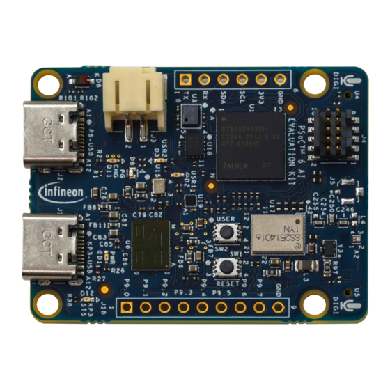
- Page 16 CY8CKIT-062S2-AI PSoC 6 AI Evaluation Kit guide ™ 2 Kit operation Figure 5 PSoC 6 AI Evaluation Board - Top view ™ Figure 6 PSoC 6 AI Evaluation Board - Bottom view ™ User guide 002-39425 Rev. ** 2024-04-19...
- Page 17 6 MCU using an external programmer such as MiniProg4. ™ XENSIV digital barometric air pressure sensor (U3): This is an Infineon digital MEMS barometric ™ pressure sensor (DPS368) with a built-in temperature sensor. This sensor uses I2C to transfer the sensor data.
-
Page 18: Using The Oob Example
The PSoC 6 AI Evaluation Board can be programmed and debugged using the onboard KitProg3. KitProg3 is an ™ onboard programmer/debugger with USB-UART and USB-I2C functionality. Infineon's PSoC 5LP device is used ™ to implement KitProg3 functionality. For more details on the KitProg3 functionality, see KitProg3 User Guide. - Page 19 CY8CKIT-062S2-AI PSoC 6 AI Evaluation Kit guide ™ 2 Kit operation Figure 7 Create new application Select the CY8CKIT-062S2-AI in the Choose BSP Target window and click Next. User guide 002-39425 Rev. ** 2024-04-19...
- Page 20 CY8CKIT-062S2-AI PSoC 6 AI Evaluation Kit guide ™ 2 Kit operation Figure 8 New application creation: Choose target BSP Select the application in the Select Application window and click Create. Figure 9 New application creation User guide 002-39425 Rev. **...
- Page 21 CY8CKIT-062S2-AI PSoC 6 AI Evaluation Kit guide ™ 2 Kit operation To build and program a PSoC 6 MCU application in the Project Explorer, select <App_Name> ™ project. In the Quick Panel, scroll to the Launches section and click the <App_Name> Program (KitProg3_MiniProg4) configuration, as shown in the following figure.
- Page 22 CY8CKIT-062S2-AI PSoC 6 AI Evaluation Kit guide ™ 2 Kit operation Figure 11 Debugging in ModusToolbox ™ User guide 002-39425 Rev. ** 2024-04-19...
-
Page 23: Hardware
CY8CKIT-062S2-AI PSoC 6 AI Evaluation Kit guide ™ 3 Hardware Hardware Schematics Refer to the schematic files available on the webpage. Hardware functional description 3.2.1 Power supply system 3.2.1.1 Power supply inputs Power supply input options for the kit. The power supply system on this board is versatile, allowing the board to be supplied from any of the following sources: •... - Page 24 CY8CKIT-062S2-AI PSoC 6 AI Evaluation Kit guide ™ 3 Hardware User guide 002-39425 Rev. ** 2024-04-19...
- Page 25 CY8CKIT-062S2-AI PSoC 6 AI Evaluation Kit guide ™ 3 Hardware Figure 13 Schematic of power supply inputs of evaluation kit The KitProg3 Type-C USB connector (J1) and PSoC 6 device USB connector (J2) can only provide 5 V/3 A, as it ™...
-
Page 26: Voltage Regulators
CY8CKIT-062S2-AI PSoC 6 AI Evaluation Kit guide ™ 3 Hardware Figure 15 Schematic of Li-Ion battery charger with power path (U8) LEDs D8 and D11 indicate the status of PGOOD (power good) signal (using D8) and battery charging (using D11). - Page 27 CY8CKIT-062S2-AI PSoC 6 AI Evaluation Kit guide ™ 3 Hardware Figure 16 Schematic of buck-boost power supply regulator (U11) Figure 17 Schematic of 3.3 V and 1.8 V LDO linear voltage regulators (U20, U21) User guide 002-39425 Rev. ** 2024-04-19...
-
Page 28: Psoc ™ 5Lp Based Kitprog3 Programmer And Debugger
CY8CKIT-062S2-AI PSoC 6 AI Evaluation Kit guide ™ 3 Hardware 3.2.2 PSoC 5LP based KitProg3 programmer and debugger ™ 3.2.2.1 PSoC 5LP based KitProg3 ™ PSoC 5LP based KitProg3 to program and debug the PSoC 6 MCU. ™ ™ The onboard PSoC 5LP (CY8C5868LTI-LP039 - U2) device is used as the KitProg3 programmer/debugger to ™... - Page 29 CY8CKIT-062S2-AI PSoC 6 AI Evaluation Kit guide ™ 3 Hardware Figure 18 Schematic of PSoC 5LP based KitProg3 ™ User guide 002-39425 Rev. ** 2024-04-19...
-
Page 30: Kitprog3 Serial Interface With Psoc ™ 6
CY8CKIT-062S2-AI PSoC 6 AI Evaluation Kit guide ™ 3 Hardware 3.2.2.2 KitProg3 serial interface with PSoC ™ I2C and UART interface between the PSoC 5LP of KitProg3 and PSoC 6 MCU ™ ™ In addition to being used as an onboard programmer/debugger using the SWD/JTAG interface, the PSoC ™... -
Page 31: Kitprog3 Programming Mode Selection Button And Status Led
CY8CKIT-062S2-AI PSoC 6 AI Evaluation Kit guide ™ 3 Hardware 3.2.2.4 KitProg3 programming mode selection button and status LED There is a mode selection button (SW3) connected to the P1[2] pin of the PSoC 5LP device for programming ™ mode selection. This button can be used to switch between Bulk and HID modes (see the KitProg3 user guide for details). -
Page 32: Psoc ™ 6 Mcu Power Supply
6 MCU datasheet. ™ In addition, Infineon's broad portfolio of hardware, software, and tool solutions, combined with Imagimob's expertise in developing robust machine learning solutions for edge devices, making it easier to leverage the advanced opportunities from AI/ML. Imagimob Studio, an end-to-end development platform, is planned for ML model creation, training, and deployment. -
Page 33: Psoc ™ 6 Mcu Io Signals
CY8CKIT-062S2-AI PSoC 6 AI Evaluation Kit guide ™ 3 Hardware Figure 21 Schematic for PSoC 6 MCU power rail connections ™ Note: R40 resistor is populated to enable the connection between the VCCD and VBUCK power supplies to bypass the internal LDO and connect the VBUCK supply to the VCCD. For using internal LDO for VCCD, remove the R40. - Page 34 CY8CKIT-062S2-AI PSoC 6 AI Evaluation Kit guide ™ 3 Hardware Table 7 PSoC 6 MCU IO ports and associated power rails ™ PSoC 6 MCU IO ports PSoC 6 MCU power rail Logic level ™ ™ VBACKUP (VCC_3V3) 3.3 V VDDD (VCC_3V3) 3.3 V...
-
Page 35: Psoc ™ 6 Mcu Clock Sources
CY8CKIT-062S2-AI PSoC 6 AI Evaluation Kit guide ™ 3 Hardware 3.2.3.3 PSoC 6 MCU clock sources ™ The PSoC 6 AI Evaluation Kit is designed to support advanced applications with its hardware features. It ™ includes a 24 MHz crystal (Y2) connected to P12[6] and P12[7]. A 32.768 KHz crystal (Y1) is connected to... -
Page 36: Psoc ™ 6 Usb Device
CY8CKIT-062S2-AI PSoC 6 AI Evaluation Kit guide ™ 3 Hardware Figure 25 PSoC 6 SWD/JTAG header interface schematic ™ The interface circuit D9 provides ESD protection, and C56 provides filtered reference voltage for external programmer to detect the target voltage of the PSoC 6 device. -
Page 37: User Leds And Power Led
CY8CKIT-062S2-AI PSoC 6 AI Evaluation Kit guide ™ 3 Hardware Figure 26 Schematic for PSoC 6 USB device interface and power supply ™ 3.2.4 User LEDs and power LED The kit contains two discrete user LEDs: D2, D3 (red), and a power LED D1 (red) for indication. -
Page 38: Reset And User Buttons
CY8CKIT-062S2-AI PSoC 6 AI Evaluation Kit guide ™ 3 Hardware Figure 28 Schematic of user LEDs 3.2.5 Reset and user buttons The board contains one reset button (SW1) for resetting the PSoC 6 MCU. When this SW1 button is pressed, the ™... -
Page 39: Xensiv ™ Digital Barometric Pressure Sensor
™ The PSoC 6 AI Evaluation Kit contains Infineon's digital barometric pressure sensor (U3) DPS368XTSA1. The ™ sensor uses an I2C interface to communicate, along with an interrupt signal, PSEN_INT_P1_4. The default I2C secondary address is 0x77. To change the address to 0x76, populate R66. -
Page 40: Xensiv ™ 60 Ghz Radar Sensor
XENSIV 60 GHz RADAR sensor ™ The PSoC 6 AI Evaluation Kit contains Infineon's XENSIV 60 GHz RADAR sensor (U6) BGT60TR13CE6327XUMA1. ™ ™ The BGT60TR13C MMIC is a 60 GHz radar sensor with integrated antennas; one transmitting and three receiving antennas. - Page 41 CY8CKIT-062S2-AI PSoC 6 AI Evaluation Kit guide ™ 3 Hardware Figure 33 Schematic of RADAR sensor interface The RADAR sensor uses power supply filters, including ferrite beads and various capacitors, as shown in the following figure. User guide 002-39425 Rev. **...
-
Page 42: 6-Axis Imu (Accelerometer + Gyroscope)
CY8CKIT-062S2-AI PSoC 6 AI Evaluation Kit guide ™ 3 Hardware Figure 34 Schematic RADAR sensor power supply filtering The following figure shows how an onboard crystal oscillator (U15) feeds 80 MHz clock input to the RADAR sensor. Figure 35 Schematic of crystal oscillator for RADAR sensor clock input 3.2.9... -
Page 43: 3-Axis Magnetometer
CY8CKIT-062S2-AI PSoC 6 AI Evaluation Kit guide ™ 3 Hardware Figure 36 Schematic of 6-axis IMU (accelerometer + gyroscope) 3.2.10 3-axis magnetometer 3-axis magnetometer for geomagnetic field direction and strength sensing This kit contains a 3-axis magnetometer sensor (U19), which is for sensing the direction and strength of the geomagnetic field. -
Page 44: Qspi Flash Memory
3.2.11 QSPI flash memory PSoC 6 AI Evaluation Kit has Infineon's onboard Quad SPI NOR flash memory S25HS512TFANHI010 (U7) of ™ 512 Mb. The NOR flash is connected to the Quad SPI interface of the PSoC 6 MCU. The NOR flash device ™... -
Page 45: Wi-Fi + Bluetooth
® 3.2.12 Wi-Fi + Bluetooth module interface The LBEE5KL1YN-814 SiP (system-in-package) module (1YN module), powered by the Infineon CYW43439 ® chipset, is a dual-mode wireless solution that offers 802.11b/g/n Wi-Fi and Bluetooth 5.2 capabilities. This module is designed for easy integration into various applications, providing reliable and high-speed wireless connectivity. - Page 46 CY8CKIT-062S2-AI PSoC 6 AI Evaluation Kit guide ™ 3 Hardware Figure 39 1YN module power supply schematic PSoC 6 device communicates to 1YN module using a standard SDIO interface for WLAN and UART interface for ™ Bluetooth ® operation. PSoC 6 device interface with 1YN module supports the following features.
- Page 47 CY8CKIT-062S2-AI PSoC 6 AI Evaluation Kit guide ™ 3 Hardware Table 15 (continued) PSoC 6 and 1YN module interface details ™ 1YN module signal PSoC 6 device Pin Description ™ BT_UART_TXD P3[0] UART serial output. Serial data output for the HCI UART interface.
-
Page 48: Io Expansion Header
CY8CKIT-062S2-AI PSoC 6 AI Evaluation Kit guide ™ 3 Hardware Figure 41 External LPO schematic 1YN module antenna output is connected to an onboard chip antenna with a matching circuit, as shown in the following figure. Figure 42 1YN module RF front-end schematic 3.2.13... - Page 49 CY8CKIT-062S2-AI PSoC 6 AI Evaluation Kit guide ™ 3 Hardware Figure 43 Schematic of the expansion header Table 16 Pin details of expansion header - J15 Pin details PSoC 6 I/O Logic level ™ J15.3 P8[2] 3.3 V J15.4 P13[7] (SDHC_DATA13) 1.8 V...
-
Page 50: I2C Interface Connector
CY8CKIT-062S2-AI PSoC 6 AI Evaluation Kit guide ™ 3 Hardware Table 16 (continued) Pin details of expansion header - J15 Pin details PSoC 6 I/O Logic level ™ J15.13 P8[5] 3.3 V J15.14 P13[2] (SDHC_DATA02) 1.8 V J15.15 P12[5] (SDHC_CLK) 1.8 V... -
Page 51: Bill Of Materials
CY8CKIT-062S2-AI PSoC 6 AI Evaluation Kit guide ™ 3 Hardware Figure 44 Schematic of I2C interface connector Table 18 Pin assignment details of I2C interface connector Pin details PSoC 6 I/O Logic level ™ J16.3 P0[3] (I2C_SDA) 3.3 V J16.4 P0[2] (I2C_SCL) 3.3 V... -
Page 52: Glossary
CY8CKIT-062S2-AI PSoC 6 AI Evaluation Kit guide ™ 4 Glossary Glossary analog-to-digital converter bill of materials direct current external crystal oscillator electrostatic discharge GPIO general purpose I/O integrated circuit integrated development environment internet of things inter-integrated circuit inter-IC sound light emitting diode... - Page 53 CY8CKIT-062S2-AI PSoC 6 AI Evaluation Kit guide ™ 4 Glossary serial peripheral interconnect SRAM static random-access memory single wire debug UART universal asynchronous receiver/transmitter universal serial bus watch crystal oscillator User guide 002-39425 Rev. ** 2024-04-19...
-
Page 54: Revision History
CY8CKIT-062S2-AI PSoC 6 AI Evaluation Kit guide ™ Revision history Revision history Document revision Date Description of changes 2024-04-19 Initial release User guide 002-39425 Rev. ** 2024-04-19... -
Page 55: Trademarks
6 AI Evaluation Kit guide ™ Trademarks Trademarks ® The Bluetooth word mark and logos are registered trademarks owned by Bluetooth SIG, Inc., and any use of such marks by Infineon is under license. User guide 002-39425 Rev. ** 2024-04-19... -
Page 56: Disclaimer
Infineon Technologies, Email: erratum@infineon.com Infineon Technologies’ products may not be used in any applications where a failure of the product or any consequences of the use thereof can reasonably be Document reference expected to result in personal injury.
Need help?
Do you have a question about the CY8CKIT-062S2-AI and is the answer not in the manual?
Questions and answers