Table of Contents
Advertisement
Quick Links
TriBoard TC3X7
TriBoard Manual TC3X7
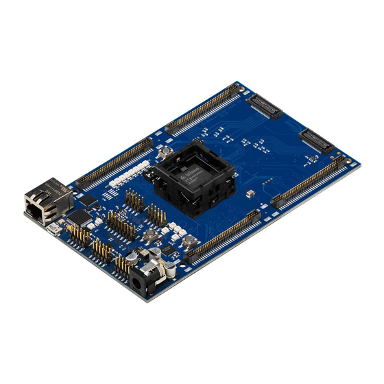
Hardware: TriBoard TC3X7 TH V2.0( 1) and TriBoard TC3X7 V2.0
About this document
Scope and purpose
The User Manual provide information about using, configuration and connecting the TriBoard with Infineon
AURIX™ TC3X7 device. The manual provide information for different hardware types. There exist different
hardware with Through Hole socket (TriBoard TC3X7 TH) and soldered devices (TriBoard TC3X7). The schematic
is identically for the all boards if not other mentioned in chapter schematic. The placing on the boards is slightly
different around the TC3X7 itself dependent of the space (socket need more space and has through hole), but the
most components are on the same location. All figures are valid for each board if not differently mentioned.
Intended audience
Design, verfication, test and software engineers will use this document to get an understanding of the
functionality and connections of the TriBoard.
User Manual
www.infineon.com
Please read the Important Notice and Warnings at the end of this document
TriBoard TC3X7 TH V2.0(1) and TriBoard TC3X7 V2.0
V2.3
2019-09
Advertisement
Table of Contents


Need help?
Do you have a question about the TriBoard AURIX TC3 7 Series and is the answer not in the manual?
Questions and answers