Advertisement
Quick Links
Advertisement

Related Manuals for aivituvin AIR96


Summary of Contents for aivituvin AIR96
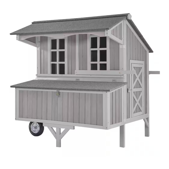
- Page 1 NSTRUCTION MANUAL AIR96...
- Page 3 NOTICE Please retain these instructions for future Firmly secure all bolts,screws and knobs before use. Reconfirm that all bolts,screws,and knobs are secure every 90 days. Fasten screws loosely during initial assembly. Do not fully tighten screws until the item is completely assembled.
-
Page 4: Tools Required
TOOLS REQUIRED PHILLIPS DRILL 2PERSON APPROXIMATELY SCREWDRIVER (RECOMMENDED) ASSEMBLY 60MIN. ASSEMBLY HARDWARE M6.0x65mm BOLT M6.0x50 mm SCREW 4 PCS+1 spare 12PCS+1 spare M3.5x60 mm SCREW M3.5x50 mm SCREW 2PCS+1 spare 28PCS+1 spare M3.5x40 mm SCREW M3.5x25 mm SCREW 20PCS+1 spare 12PCS+1 spare Spring latch M3.0x16mm SCREW... - Page 5 HARDWARE Waterproof PVC Corner Bracket 8PCS Corner bracket 4PCS...
- Page 6 PARTS CARTON 1/2 Caster connect parts Casters Back panel-Down 2PCS 2PCS Front panel-Down Front panel-Upper Left panel Right panel of roof Left panel of roof Right panel...
- Page 7 PARTS Hardware bag Tray...
- Page 8 PARTS CARTON 2 /2 Left panels of nesting box Back panel-Upper Coop Supports 2PCS Front panel of roof Front panel of nesting box Push handle 2PCS Nesting box floors Divider of nesting box Support frame 2PCS 3PCS...
- Page 9 PARTS Roof of coop Perches Roof of coop 3PCS Roof of nesting box Waterproof strip Roof of coop Roof cap Right panels of nesting box 2PCS...
-
Page 10: Product Assembly
PRODUCT ASSEMBLY ①Attach Part H by 4 X P4 screws, then attach Part E to Part D by 6 X P4&2 X P3 screws. ② Attach the coop supports Part K to right panel by 4 X P4 screws. Connect part Axle Caster Gasket... - Page 11 PRODUCT ASSEMBLY Attach the Part F&Part G to side panel Part C&Part D by 12 X P4 screws. ① Attach Part H to Parc C by 4 X P4 screws, then attach Part E to Part D by 6 X P4&2 X P3 screws.
- Page 12 PRODUCT ASSEMBLY ① Attach the Corner bracket P11 to Front panel Part E by 4 X P7 screws each side. ② Attach the latch P8 to door by 2 X P7 screws, then attach the corner bracket 2xP10 to the corner by 4xP7 each side. Pls note: The corner bracket need to be screwed on the inside edge...
- Page 13 PRODUCT ASSEMBLY ① Attach the Corner bracket P11 to Back panel Part H by 4 X P7 screws each side. ② Attach the latch P8 to door by 2 X P7 screws, then attach the corner bracket 2xP10 to the corner by 4xP7 each side. Pls note: The corner bracket need to be screwed on the inside edge...
- Page 14 PRODUCT ASSEMBLY Attached the push handle Part L to the coop by 2XP2 bolts each side. Attached the I1,I2,J1,J2 to the coop by 2XP2 bolts each side.
- Page 15 PRODUCT ASSEMBLY Attach the corner bracket 4xP10 to the corner by 4xP7 each side. Attach the Front panel of roof Part N by 4xP5.
- Page 16 PRODUCT ASSEMBLY ① Attach the Support frame Part O to Front panel of nesting box Part M by 2 X P4 screws. ② Attach Part M to the coop by 4 X P5 screws. Attach the 3 x Nesting box floors Part Q first, then attach 2 x Divider of nesting box Part P to the nesting box.
- Page 17 PRODUCT ASSEMBLY ①Insert 3 x Perches Part R into the slots inside two side panels. ②Slide in tray Part S inside. Attach the nesting box roof Part W by 6XP7 screws.
- Page 18 PRODUCT ASSEMBLY Attach the Roof of coop U,V,T by 12XP5 screws. Attach the Waterproof strip Part X by 4XP6 screws.
- Page 19 PRODUCT ASSEMBLY ① Put the Waterproof PVC P9 in the connection position of 2 roof cap to avoid the water leakage. ② Attach Roof cap Part I to the coop by 8 X P6 screws. Finish...
- Page 20 WARNING Manufacturer and seller expressly disclaim any and all liability for personal injury,property damage or loss,whether direct,indirect,or incidental,resulting from the incorrect attachment,improper use,inadequate miantenance,or neglect of this...
Need help?
Do you have a question about the AIR96 and is the answer not in the manual?
Questions and answers