
Related Manuals for SMITH SYSTEM Flowform


Summary of Contents for SMITH SYSTEM Flowform
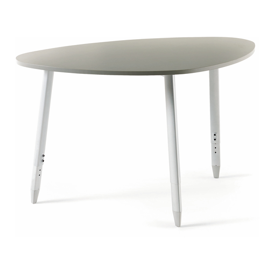
- Page 1 Assembly Instructions Flowform Adjustable Height Tables If you have damaged or missing components, please contact customer service at 1-800-328-1061 Document #: 179687 REVISED: 10/2020...
- Page 2 Hardware and Components ORBIT TOP WITH FRAME ORBIT TOP, NO FRAME (MAY APPEAR DIFFERENT THAN SHOWN) (MAY APPEAR DIFFERENT THAN SHOWN) QTY. 1 QTY. 1 PACK #60001 PACK #60002 ( 3 TO 4 LEGS PER TABLE ) ( 3 TO 4 LEGS PER TABLE ) ORBIT LEG FOR CASTER QTY.
-
Page 3: Special Notes
Special Notes: TOOLS REQUIRED: • Drill w/#2 Phillips driver bit, or #2 Phillips head screwdriver. Check that all components are accounted for and undamaged before assembling. Please assemble the product in a clean and dry area. You may need another person to help assemble the product. Team lifting may be required. - Page 4 Assembly Instructions 1. FOR LEGS WITH GLIDES: Insert either the Nylon or Felt Tip into the Glide. Press down on tip until it snaps into place. Helpful Hint: It is recommended that the Nylon Glide Tip is used for carpeted areas and the Felt Glide Tip is used for hard surfaces such as hardwood floors.
- Page 5 3. FOR FRAMELESS TABLES: Lay top down on a clean smooth surface that will not harm the top finish. Underside of top should be exposed. Top may be heavy, team lifting is encouraged. 4. Align leg mounting plate holes with pilot holes on underside of top. Install all 14 of the #10 x 3/4”...
- Page 6 6. Install the other legs as previously shown. 7. FOR TABLES WITH FRAMES: Lay top down on a clean smooth surface that will not harm the top finish. Underside of top and frame should be exposed. Top may be heavy, team lifting is encouraged.
- Page 7 9. Install 13 of the #10 x 3/4” Hi-Lo Wood Screws to secure the leg to the top leaving out one of the screws as the hole is covered by the frame. 10. Next install the 5/16”-18 x 1/2” Bolts to connect the frame to the leg gusset. 11.
- Page 8 12. TO ADJUST LEG HEIGHT: Remove the two 3/8”-16 x 5/8” set screws, adjust leg to the desired height and reinstall the two set screws. Repeat this for all legs. Helpful Hint: The spacing between each hole in the inner leg is for 1” of adjustment. 13.
Need help?
Do you have a question about the Flowform and is the answer not in the manual?
Questions and answers