
Subscribe to Our Youtube Channel
Related Manuals for Advantech UNO-2171


Summary of Contents for Advantech UNO-2171
- Page 1 UNO-2171 Pentium-M/Celeron-M Universal Network Controller with PC/104+ Expansion User Manual...
- Page 2 Microsoft Windows and MS-DOS are registered trademarks of Microsoft Corp. C&T is a trademark of Chips and Technologies, Inc. All other product names or trademarks are properties of their respective owners. This manual is for UNO-2171. Part No. 2003217101 2nd Edition Printed in Taiwan August 2007...
- Page 3 Product Warranty Advantech warrants to you, the original purchaser, that each of its prod- ucts will be free from defects in materials and workmanship for one year from the date of purchase. This warranty does not apply to any products that have been repaired or...
- Page 4 This product has passed the CE test for environmental specifications when shielded cables are used for external wiring. We recommend the use of shielded cables. This kind of cable is available from Advantech. Please contact your local supplier for ordering information.
-
Page 5: Table Of Contents
Figure 1.2:Chassis Dimensions 2........5 Figure 1.3:Chassis Dimensions 3........5 Chapter 2 Hardware Functionality ........8 Introduction ............... 8 Figure 2.1:UNO-2171 Front Panel ......... 8 Figure 2.2:UNO-2171 Rear Panel ........8 RS-232 Interface (COM1~COM2) ........8 RS-232/422/485 Interface (COM3~COM4) ..... 9 2.3.1 16C550 UARTs with 16-byte standard ...... - Page 6 BIOS Setup and System Assignments ......20 Appendix A System Settings & Pin Assignments .....22 System I/O Address & Interrupt Assignments....22 Table A.1: UNO-2171 System I/O Ports ...... 22 Board Connectors and Jumpers........24 Figure A.1:Connectors & Jumpers (frontside) ..... 24 Figure A.2:Connectors &...
- Page 7 Overview This chapter provides an overview of UNO-2171’s specifications. Sections include: • Introduction • Hardware specification • Safety precautions • Chassis dimensions...
-
Page 8: Chapter 1 Overview
Chapter 1 Overview 1.1 Introduction UNO-2171 is an embedded Application Ready Platform (ARP) that can shorten your development time and offers rich networking interfaces to fulfill extensive needs in different projects. Advantech’s Universal Net- work Controller is designed to be a total solution for network enabled Application Ready Platforms. -
Page 9: Hardware Specifications
1.2 Hardware Specifications • CPU: Pentium M 1.4GHZ / Celeron M 1 GHZ • Memory: 512MB/1GB on board • Battery-backup RAM: 512 KB Battery-backup RAM • VGA/Keyboard/Mouse: DB-15 VGA Connector, PS/2 keyboard & mouse • Serial Ports: 2 × RS-232 and 2 x RS-232/422/485 with DB-9 connectors. Automatic RS-485 data flow control •... -
Page 10: Safety Precautions
Caution! Always ground yourself to remove any static electric charge before touching UNO-2171. Mod- ern electronic devices are very sensitive to static electric charges. Use a grounding wrist strap at all times. Place all electronic components on a static-dissipative surface or in a static-shielded bag. -
Page 11: Chassis Dimensions
1.4 Chassis Dimensions Figure 1.1: Chassis Dimensions 1 Figure 1.2: Chassis Dimensions 2 Figure 1.3: Chassis Dimensions 3 Chapter 1... - Page 12 UNO-2171 User Manual...
- Page 13 Hardware Functionality This chapter shows how to setup the UNO-2171’s hardware functions, including connecting peripherals, set- ting switches and indicators. Sections include: • Peripherals • RS-232 Interface • RS-232/422/485 Interface • LAN / Ethernet Connector • Power Connector • PS/2 Mouse and Keyboard Connector •...
-
Page 14: Chapter 2 Hardware Functionality
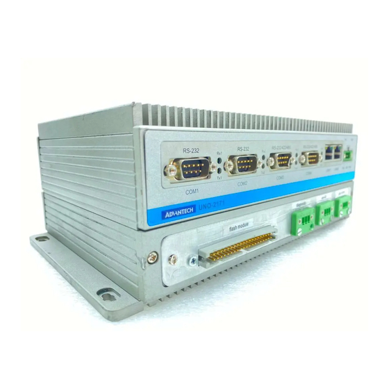
Chapter 2 Hardware Functionality 2.1 Introduction The following two figures show the connectors on UNO-2171. The fol- lowing sections give you detailed information about function of each peripheral. Figure 2.1: UNO-2171 Front Panel Figure 2.2: UNO-2171 Rear Panel 2.2 RS-232 Interface (COM1~COM2) The UNO-2171 offers two standard RS-232 serial communication inter- face ports: COM1 and COM2. -
Page 15: Rs-232/422/485 Interface (Com3~Com4)
COM3 and COM4. Please refer to Appendix A.4 for their pin assignments. The default setting of COM3 and COM4 are RS-422/485. 2.3.1 16C550 UARTs with 16-byte standard Advantech UNO-2171 comes with TI16C550 UARTs containing 16 bytes FIFOs. 2.3.2 RS-422/485 detection In RS-422/485 mode, UNO-2171 automatically detects signals to match RS-422 or RS-485 networks. -
Page 16: Rs-232/422/485 Selection
To select between RS-422/485 and RS-232 for COM4, adjust JP8. Jumper setting for RS-422/485 interface: (Default setting). (JP7 and JP8) Figure 2.3: RS-422/485 Jumper Setting Jumper setting for RS-232 interface: (JP7 and JP8) Figure 2.4: RS-232 Jumper Setting UNO-2171 User Manual... -
Page 17: Rs-485 Auto Flow & Rs-422 Master/Slave Mode
2.3.6 RS-485 Auto Flow & RS-422 Master/Slave Mode You can set the “Auto Flow Control” mode of RS-485 or “Master/Slave” mode of RS-422 by using the SW4 DIP switch for each RS-422/485 port. In RS-485, if the switch is set to “Auto”, the driver automatically senses the direction of the data flow and switches the direction of transmission. -
Page 18: Irq And Address Setting
Speed x 8* Speed x 1 (default) * To increase the normal baud rates by eight times, (e.g. if 115.2K bps is set, the baud rate will be increased to 921.6K bps), set switch 2 of SW5 to “on”. UNO-2171 User Manual... -
Page 19: Lan: Ethernet Connector
2.6 PS/2 Keyboard and Mouse Connector The UNO-2171 provides a PS/2 keyboard and PS/2 mouse connector. A 6-pin mini-DIN connector is located on the rear panel of the UNO-2171. The UNO-2171 comes with an adapter to convert from the 6-pin mini- DIN connector to two 6-pin mini-DIN connectors for PS/2 keyboard and PS/2 mouse connection. -
Page 20: Pcmcia: Pc Card Slot
There is a BTRY LED in the front panel of the UNO-2171, please replace the lithium battery with a new one if the BTRY LED is activated. -
Page 21: Reset Button
2.11 Reset Button Press the "Reset" button to activate the reset function. (SW2) 2.12 Power Button Press the "Power" button to power on or power off UNO-2171. (ATX type) (SW3) UNO-2171's power is also designed for power management only "S1"... -
Page 22: Audio
- Line In - Line Out. 2.14 PC/104+ UNO-2171 supports standard PC/104+ version 1.2, which supports up to 3 PCI masters (CN20). You also could install jumper (JP10) for choosing power of PC/104+ bus supplies (Jumper default setting is open). - Page 23 Initial Setup This chapter introduces how to initial- ize the UNO-2171. Sections include: • Chassis Grounding • Inserting a CompactFlash Card • Installing a Hard Disk • Connecting Power • BIOS Setup and System Assignments...
-
Page 24: Chapter 3 Initial Setup
Chapter 3 Initial Setup 3.1 Chassis Grounding The aluminum made UNO-2171 provides good EMI protection and a sta- ble grounding base. There is an easy-to-connect chassis grounding point for you to use. Please connect chassis ground of UNO-2171 with "EARTH" as ground. -
Page 25: Inserting A Compactflash Card
HDD, please install CF in CN10 and connect HDD in CN8. 3.3 Installing a Hard Disk The procedure for installing a hard disk into the UNO-2171 is below. Please follow these steps carefully. Remove the power cord. -
Page 26: Connecting Power
CF in CN10 and connect HDD in CN8. 3.4 Connecting Power Connect the UNO-2171 to a 10~53 VDC power source. The power source can either be from a power adapter or an in-house power source. 3.5 BIOS Setup and System Assignments UNO-2171 adopts Advantech’s SOM-4486/4481 CPU module. - Page 27 System Settings and Pin Assignments...
-
Page 28: Appendix A System Settings & Pin Assignments
Appendix A System Settings & Pin Assignments A.1 System I/O Address & Interrupt Assignments Table A.1: UNO-2171 System I/O Ports Address Range Device 000-01F DMA controller (slave) 020-03F Interrupt controller 1, (master) 040-05F 8254 timer/counter 060-06F 8042 (keyboard controller) 070-07F... - Page 29 Table A.1: UNO-2171 System I/O Ports Address Range Device 3F8-3FF Serial port 1 DC000-DFFFF Battery backup resource Table A.2: UNO-2171 Interrupt Assignment Interrupt No. Interrupt Source Parity error detected IRQ 0 Interval timer IRQ 1 Keyboard IRQ 2 Interrupt from controller 2 (cascade)
-
Page 30: Board Connectors And Jumpers
A.2 Board Connectors and Jumpers There are several connectors and jumpers on the UNO-2171 board. The following sections tell you how to configure the UNO-2171 hardware setting. Figure A-1 and Figure A-2 show the locations of UNO-2171’s connectors and jumpers. - Page 31 Table A.3: UNO-2171 Connectors and Jumpers Label Function Phoenix power connector Ethernet port 1 Ethernet port 2 COM1 RS-232 serial port COM2 RS-232 serial port CN15 COM3 RS-232/422/485 serial port CN16 COM4 RS-232/422/485 serial port USB connector PS/2 keyboard and mouse connector...
-
Page 32: Rs-232 Standard Serial Port (Com1~Com2)
A.3 RS-232 Standard Serial Port (COM1~COM2) Table A.4: RS-232 standard serial port pin assignments RS-232 Signal Name UNO-2171 User Manual... -
Page 33: Rs-232/422/485 Serial Port (Com3~Com4)
A.4 RS-232/422/485 Serial Port (COM3~COM4) Table A.5: RS-232/422/485 serial port pin assignments RS-232 RS-422 RS-485 DATA- DATA+ A.5 Ethernet RJ-45 Connector (LAN1~LAN2) Table A.6: Ethernet RJ-45 connector pin assignments 10/100Base-T Signal Name XMT+ XMT- RCV+ RCV- Appendix A... -
Page 34: Phoenix Power Connector (Pwr)
A.6 Phoenix Power Connector (PWR) Table A.7: Power connector pin assignments Signal Name +10~53 VDC A.7 PS/2 Keyboard and Mouse Connector Table A.8: Keyboard and Mouse connector pin assignments Signal Name KB DATA MS DATA KB Clock MS Clock UNO-2171 User Manual... -
Page 35: Usb Connector (Usb1~Usb2)
A.8 USB Connector (USB1~USB2) Table A.9: USB connector pin assignments Signal Name Cable Color DATA- White DATA+ Green Black A.9 VGA Display Connector Table A.10: VGA adaptor cable pin assignment Signal Name Green Blue H-SYNC V-SYNC Appendix A... - Page 36 UNO-2171 User Manual...
- Page 37 Programming the Watchdog Timer...
-
Page 38: Appendix B Programming The Watchdog Timer
OUT DX,AL MOV DX,2FH MOV AL,00H OUT DX,AL; MOV DX,2EH MOV AL,F6H OUT DX,AL MOV DX,2FH MOV AL,05H; Set 5 seconds OUT DX,AL ;------------------------------------------ ; Exit extended function mode | ;------------------------------------------ MOV DX,2EH MOV AL,AAH OUT DX,AL UNO-2171 User Manual...
Need help?
Do you have a question about the UNO-2171 and is the answer not in the manual?
Questions and answers