Table of Contents
Advertisement
Quick Links
Advertisement
Table of Contents

Related Manuals for 2N Indoor View


Summary of Contents for 2N Indoor View
- Page 1 2N® Indoor View User Manual v.2.40 www.2n.com...
-
Page 2: Table Of Contents
2. Description and Installation • 2.1 Before You Start • 2.2 Quick Installation Guide • 2.3 Installation Conditions • 2.4 2N® Indoor View LAN Location via 2N® Network Scanner • 2.5 IP Address Lookup • 3. Configuration • 3.1 Factory Reset •... - Page 3 2N Telekomunikace a.s. ® Indoor View is equipped with a specific user interface for an increased user comfort and safety. ® Indoor View basic features •...
-
Page 4: Differences Between Models And Associated Products
2N® Indoor View User Manual 1.2 Differences between Models and Associated Products ® Indoor View indoor units ® • Indoor View – black • Indoor answering audio/video unit with touchscreen 2N Part No. 91378601 designed for all 2N IP intercoms Axis Part No. 02087-001 ... - Page 5 • Indoor Touch 2.0, an elegant indoor touch panel, is designed for 91378375 all of the 2N IP intercoms. The display panel shows you the person standing at your door and helps you make conversation with the Axis Part No.
- Page 6 • Indoor Touch 2.0, an elegant indoor touch panel, is designed for 91378375WH all of the 2N IP intercoms. The display panel shows you the person standing at your door and helps you make conversation with the Axis Part No.
- Page 7 2N® Indoor View User Manual ® • Indoor Compact – black • Indoor answering audio/video unit with touchscreen designed for all 2N Part No. 2N IP intercoms 91378501 Axis Part No. 01935-001 ® • Indoor Compact – white • Indoor answering audio/video unit with touchscreen designed for all 2N Part No.
- Page 8 2N Part No. intercoms 91378401WH Axis Part No. 01699-001 Mounting Accessories • Installation box for 2N indoor answering units for installation in a wall or plasterboard. 2N Part No. ® • Not included in the 2N Indoor View package. 91378800 Axis Part No.
- Page 9 2N® Indoor View User Manual • Wall mounting box for 2N answering units ® • Not included in the 2N Indoor View package. 2N Part No. 91378803 Axis Part No. 02320-001 • Stand for the 2N indoor answering unit. ®...
- Page 10 2N® Indoor View User Manual VoIP Phones • Grandstream GXV3240 VoIP video telephone • GXV3240 is the successor to the popular GXV3140 2N Part No. 91378358 model, which provides comfortable video calls in Axis Part No. 01421-001 the IP network. Touchscreen and keypad control.
-
Page 11: Terms And Symbols Used
Ethernet cable can only be carried to the required site. ® • Install 2N Indoor View out of reach of sensitive devices and human bodies as it emits electromagnetic interference. • The permitted scope of operating temperatures is specified in chapter 6. - Page 12 2N® Indoor View User Manual ® • Indoor View is designed for indoor use. It may not be exposed to rain, flowing water, condensing moisture, fog, and so on. • It may not be exposed to aggressive gases, acid and solvent vapors, etc.
-
Page 13: Description And Installation
• 2.2 Quick Installation Guide • 2.3 Installation Conditions • 2.4 2N® Indoor View LAN Location via 2N® Network Scanner • 2.5 IP Address Lookup 2.1 Before You Start Package Completeness Check Please check the product delivery before starting installation: Contents: ®... - Page 14 2N® Indoor View User Manual Front Layout Display Microphone Speaker Anchoring holes 14 / 132...
- Page 15 Ethernet ® Indoor View is designed for flush mounting (brick, plasterboard, wood). Use the flush mounting box (Part No. 91378800), which is not included in the package. Alternatively, the product can be mounted into a desk stand (Part No. 91378802), which is not included in the package.
- Page 16 2N® Indoor View User Manual Caution • Before starting the mechanical installation on a selected place, make sure carefully that the preparations connected with it (drilling, wall cutting) cannot damage the electrical, gas, water and other existing wires and pipes.
-
Page 17: Quick Installation Guide
First plug the green power/ doorbell connector. Connect the LAN connector. Put the cables carefully in the pre-drilled ® Indoor View back slot to prevent them from blocking any horizontal levelling movement ® during the final installation stage. Insert 2N Indoor View in the flush mounting box making sure that it clicks onto the levelling pins, The pins allow for a 5–6 °... -
Page 18: Installation Conditions
® provided. Level 2N Indoor View with a water level and tighten the screws ® gently. Now 2N Indoor View is ready for basic operation. Alternatively, install the device in a stand. Within installation preparations, take out the pre- prepared cabling, UTP cable, doorbell (twin) cable and power supply. - Page 19 Use an Ethernet cable connected to a PoE supply or PoE supporting Ethernet switch/ router. PoE Supply Connection ® Use a standard straight RJ-45 terminated cable to connect 2N Indoor View to the Ethernet. The device supports the 10BaseT and 100BaseT protocols. ...
-
Page 20: Indoor View Lan Location Via 2N® Network Scanner
2.4 2N® Indoor View LAN Location via 2N® Network Scanner ® Indoor View is configured via the administration web server. Connect the device to the LAN IP and make sure it is properly powered. 20 / 132... - Page 21 ® Having installed the 2N IP Network Scanner, start the application using the Microsoft Windows Start menu. Once started, the application begins to automatically search for all the 2N IP intercoms in the ® ® ® LAN including their smart extensions (2N Indoor View, 2N...
- Page 22 IP address, select Config and enter the required static IP address or activate DHCP. The default configuration password is 2n. If the found device is grey highlighted, its IP address cannot be configured using this application. In that case, click Refresh to find the device again and check whether multicast is enabled in your network.
-
Page 23: Ip Address Lookup
® To find the 2N Indoor View IP address using the display, press any key on the display to quit the sleep mode. The Settings menu is displayed on the home screen after pressing the settings 23 / 132... - Page 24 Dynamic/Static IP Address Switching ® Indoor View is connected to the LAN and has to be assigned a valid IP address or obtain the IP address from the LAN DCHP server. Configure the IP address and DHCP in the System / Network menu.
- Page 25 2N® Indoor View User Manual • Static IP Address – static IP address of the device. The address is used together with the parameters below unless Use DHCP server is enabled. • Network mask – set the network mask. •...
-
Page 26: Configuration
Password: 2n Should the login screen fail to appear, you must have typed a wrong IP address/port or ® the 2N Indoor View administration web server has been switched off. To find the correct IP ® ® address, use the 2N Network Scanner as described in 2.4 2N®... - Page 27 Note • The delay after pressing RESET till the first light and sound signalling is set to 15– 35 s depending on the 2N IP intercom/answering unit model used. ® • The time interval 18 s applies to the 2N Indoor View.
- Page 28 2N® Indoor View User Manual Dynamic IP Address Setting Follow the instructions below to switch on the Static IP address mode (DCHP ON): • Press and hold the RESET button. • Wait until the red and green LEDs go on simultaneously on the device and the acoustic signal can be heard (approx.
- Page 29 2N® Indoor View User Manual • Wait until the red and green LEDs go on simultaneously and the acoustic signal can be heard (approx. 15–35 s). • Wait until the red LED goes off and the acoustic signal can be heard (approx. for another 3 s).
- Page 30 Press the button shortly (< 1 s) to restart the system without changing configuration. Note ® • For the 2N Indoor View, the time interval between a quick press of the RESET button and reconnection of the device to the network is 20 s. 30 / 132...
-
Page 31: Software Configuration
Click the Log out button in the right-hand upper corner to log out. The start screen also provides the first menu level and quick tile navigation to selected ® Indoor View configuration sections. Some tiles also display the state of selected services. • 3.2.1 Status •... - Page 32 2N® Indoor View User Manual 3.2.1 Status The Status menu provides clear status and other essential information on the intercom. The menu is divided into four tabs: Device, Services, Call Log and Events. • 3.2.1.1 Device • 3.2.1.2 Services • 3.2.1.3 Call Log • 3.2.1.4 Events 3.2.1.1 Device...
- Page 33 ACS. • Locate device – optical and acoustic signalling of a device. Optical signalling is possible ® ® ® only if the device is equipped with control backlight (2N IP Style, 2N IP Verso, 2N IP ® Solo, 2N IP...
- Page 34 2N® Indoor View User Manual Services The Services tab displays the status of the network interface and selected services. 34 / 132...
- Page 35 2N® Indoor View User Manual 3.2.1.3 Call Log The Call Log displays a list of all accomplished calls. Each call includes the contact type, called/ calling user ID, call date and time, call duration and status (incoming, outgoing, missed, picked up elsewhere, doorbell button).
- Page 36 2N® Indoor View User Manual 3.2.1.4 Events Events The tab displays the last 500 events captured by the device. Every event includes the capturing time and date, event type and detailed description. The events can be filtered by type in a dropdown menu above the event log.
- Page 37 2N® Indoor View User Manual CallSessionStateChanged Event describing the call direction/state, address, session number and call sequence number. CallStateChanged Indicates the call direction (incoming, outgoing) and opponent / SIP account identification at a call state change (ringing, connected, terminated). DeviceState Device state indication, startup of the device, for example.
- Page 38 3.2.2.3 Svátky 3.2.2.1 Devices Directory is one of the crucial parts of the device configuration. It helps add new devices (2N IP intercoms and other answering units) and provides essential information on them. Up to 200 devices can be added to the directory.
- Page 39 Phone Number – enter the phone number of the station to which the call shall be routed. Enter sip:[user_id@]domain[:port] for Direct SIP calling, e.g.: sip:200@192.168.22.15 or ® sip:name@yourcompany. Enter device:device_name for calls to the 2N IP Mobile application. Set the device name in the mobile application. Enter/1 or/2 behind the phone number to specify which SIP account shall be used for outgoing calls (account 1 or 2).
- Page 40 With some 2N terminal equipment in the LAN, the information sent by the 2N terminal equipment is preferred to this setting (i.e. this setting is not needed for contacts using 2N terminals or camera-less devices).
- Page 41 2N® Indoor View User Manual Cameras Assigned to This Device – enter the comma-separated camera numbers 1–16 in the order that should be browsed during the calls with this device. The cameras are configured in the Hardware > Camera section. Forbidden cameras will be skipped.
- Page 42 Once saved, the contact will be shown in the phone book on the device display. Make sure that Local calls is enabled on the called 2N device to make a successful call. Connection with Other Devices Click the icon to create a new contact or open an existing contact detail.
- Page 43 Enter the calling destination address into the destination field to which the call is to be routed. Complete SIP URI in the format user_name@host or the target IP address (e.g.: johana@255.0.255.0 or johana@calls.2N.com). For local calls, fill in the called 2N device ID, refer to Local Calls in 3.2.3.1.
- Page 44 Assign a time profile according to a week time sheet to define availability of the selected function. Just set from-to or days in the week on which the function shall be available. 2N IP intercom helps you create up to 20 time profiles (depending on the 2N IP intercom model) that can be assigned to the function;...
- Page 45 2N® Indoor View User Manual This parameter helps you set time profiles within a week period. A profile is active when it matches the set intervals. If a day is marked as holiday (refer to Directory → Holidays), the last table row (Holiday) is applied regardless of the day in a week.
- Page 46 2N® Indoor View User Manual 3.2.2.3 Svátky Here select the bank holidays (including Sundays). You can assign them different time intervals than to working days in their time profiles. You can set holidays for the coming 10 years (click the year number at the top of the screen to select a year).
- Page 47 2N® Indoor View User Manual 3.2.3 Services Here is what you can find in this section: • 3.2.3.1. Phone • 3.2.3.2 Unlocking • 3.2.3.3 HTTP Command • 3.2.3.4 User Sounds • 3.2.3.5 Web Server • 3.2.3.6 Weather 47 / 132...
- Page 48 Audio – audio codec, DTMF and other audio stream parameter transmission settings. • Video – video codec and SDP codec settings. • 2N Indoor Units – general parameters and count of identified LAN devices. SIP 1 and SIP 2 ® Two SIP accounts can be configured on 2N Indoor View.
- Page 49 2N® Indoor View User Manual • Display Name – set the name to be displayed as CLIP on the called party's phone. • Phone Number (ID) – set your device phone number (or another unique ID composed of characters and digits). Together with the domain, this number uniquely identifies the device in calls and registration.
- Page 50 2N® Indoor View User Manual • Proxy Address – set the SIP Proxy IP address or domain name. • Proxy Port – set the SIP Proxy port (typically 5060). • Backup Proxy Address – set the backup SIP Proxy IP address or domain name. The address is used where the main proxy fails to respond to requests.
- Page 51 2N® Indoor View User Manual • SIP Transport Protocol – set the SIP communication protocol: UDP (default), TCP or TLS. • Lowest Allowed TLS Version – set the lowest TLS version to be accepted for device connection. • Verify Server Certificate – verify the SIP server public certificate against the CA certificates uploaded in the device.
- Page 52 2N® Indoor View User Manual • IP Address Filter Enabled – enable the blocking of SIP packet receiving from addresses other than SIP Proxy and SIP Registrar. The primary purpose of the function is to enhance communication security and eliminate unauthorized phone calls.
- Page 53 2N® Indoor View User Manual • Call Answering Mode (SIP 1, SIP 2) – set the way of receiving incoming calls. The following three options are available: • Always busy – the device rejects incoming calls. • Manual answering – the device rings to signal incoming calls and the user can press a keypad button to pick up.
- Page 54 2N® Indoor View User Manual • – select one of the pre-defined profiles or set the time profile for the given element manually. • Connecting Time Limit – set the maximum outgoing call connection timeout after which the calls are automatically terminated. If the calls are routed to the GSM network via GSM gateways, you are advised to set a value higher than 20 s.
- Page 55 2N® Indoor View User Manual Audio Enable/disable the use of audio codecs for call setups and set their priorities. The tab below helps you define how DTMF characters shall be sent from the intercom. Check the opponent’s DTMF receiving options and settings to make the function work properly.
- Page 56 2N® Indoor View User Manual • In-Band (Audio) – enable classic DTMF dual tone receiving in the audio band. • RTP (RFC-2833) – enable DTMF receiving via RTP according to RFC-2833. • SIP INFO (RFC-2976) – enable DTMF receiving via SIP INFO messages according to RFC-2976.
- Page 57 2N® Indoor View User Manual • H.264 Baseline Profile, Packetization Mode 1 • H.264 Baseline Profile, Packetization Mode 0 • H.264 Main Profile, Packetization Mode 1 • H.264 Main Profile, Packetization Mode 0 • H.264 High Profile, Packetization Mode 1 •...
- Page 58 • Device ID – set the device ID to be displayed in the LAN device list in all the 2N devices in one and the same LAN. You can direct a call to this device by setting the user phone number as device:device_ID in these devices. ...
- Page 59 Show LAN device list – display a detailed list of local devices in the network. 3.2.3.2 Unlocking ® Unlocking is another function of 2N Indoor View, which sets the remote door unlocking parameters. • Default Unlock Code – use this code when a call has been set up with a device/phone number that is not added to the unit phone book.
- Page 60 ® HTTP Command on the 2N Indoor View answering unit helps you send up to 3 selected HTTP commands by a button press. The buttons are displayed on the Home page under the selected icon in case the function is set.
- Page 61 3.2.3.4 User Sounds ® Indoor View signals variable operational statuses with a sequence of tones. If the standard signaling tones do not meet your requirements, you can modify them. The device allows you to modify sound signaling for the following states:...
- Page 62 2N® Indoor View User Manual • Busy Tone – set the busy tone (to be played when the called user is busy). • Call End Signaling – set the sound to be played upon the call end. • Ringtone – set the sound to be played when the called user is ringing.
- Page 63 2N® Indoor View User Manual You can upload up to 10 user sound files to the device and name each of them for better orientation. Press to upload a sound file to the device. Select a file from your PC and click Upload. Press to remove a file.
- Page 64 The HTTPS protocol is used for the browser - device communication. Enter the login user name and password first. The default values are admin and 2n respectively. We recommend to you change the default password as soon as possible.
- Page 65 2N® Indoor View User Manual • HTTP Port – set the web server port for HTTP communication. The port change will not be applied until the device is restarted. • HTTPS Port – set the web server port for HTTPS communication. The port change will not be applied until the device is restarted.
- Page 66 2N® Indoor View User Manual 3.2.3.6 Weather The Weather service displays the current weather information for the selected location on the ® Indoor View home screen. • Show Weather – allow the device to display the current weather information. • Location – set the device location for weather forecast. If Show Weather is enabled and the Location parameter is empty, Prague will be displayed by default.
- Page 67 2N® Indoor View User Manual • Last Update – precise date of the last server data update. • Location Found – weather forecast location found by the weather service. • Country – country of the automatically defined or completed location. 67 / 132...
- Page 68 2N® Indoor View User Manual 3.2.4 Hardware Here is what you can find in this section: • 3.2.4.1 Audio • 3.2.4.2 Camera • 3.2.4.3 Display • 3.2.4.4 Digital Inputs 68 / 132...
- Page 69 3.2.4.1 Audio ® Indoor View is equipped with a speaker. Set the phone call and state signaling volume control in this configuration section. Master Volume controls the general device volume including call volume, signaling tone volume, and so on. Consider the noise level of the ambient environment while setting this parameter.
- Page 70 2N® Indoor View User Manual • Warning Tone Volume – set the volume of warning and signaling tones. The volume values are relative against the set master volume. • Suppress Warning Tones – suppress signaling of the following operational states: Internal application started, IP address received and IP address lost.
- Page 71 2N® Indoor View User Manual • Language – set the language of the texts to be displayed. Choose one of the eight pre- defined languages (CZ, EN, DE, NL, FR, ES, IT, RU). • Date Format – set the date format to be displayed.
- Page 72 2N® Indoor View User Manual • Original Language – download a preset XML file with all the texts to be displayed. It is an XML file with all the texts to be displayed. • Custom Language – remove, download and upload a localization file of your own.
- Page 73 3.2.4.2 Camera ® Indoor View helps you configure up to 16 external cameras for video call streaming. Standard external IP cameras supporting RTSP streams with the MJPEG or H.264 codecs can be connected. The maximum resolution of the stream received is 1280 x 720 px. The maximum recommended frame rates are 30 fps for H.264 and 15 fps for MJPEG.
- Page 74 • RTSP Stream Address – enter the IP camera RTSP stream address: rtsp:// camera_ip_address/parameters. The parameters are specific for the selected IP camera model. If you choose another 2N IP intercom for the external camera, enter http:// ip_address/mjpeg_stream or http://ip_address/h264_stream. • Username – enter the username for the external IP camera authentication. The parameter is obligatory only if the external IP camera requires authentication.
- Page 75 2N® Indoor View User Manual The External IP Camera Log displays the RTSP communication with the selected external IP camera including failures and error states if any. 3.2.4.4 Digital Inputs This subsection describes the digital input options of the device.
- Page 76 2N® Indoor View User Manual • Camera Assigned to Doorbell Button – select the external camera to be displayed when the door bell is ringing. This camera video display does not interrupt any active call/ringing. Tap on the green bar in the display upper part to return to the call/ringing.
- Page 77 2N® Indoor View User Manual 3.2.5 System Here is what you can find in this section: • 3.2.5.1 Network • 3.2.5.2 Date and Time • 3.2.5.3 Certificates • 3.2.5.4 Auto Provisioning • 3.2.5.5 Syslog • 3.2.5.6 Maintenance 77 / 132...
- Page 78 3.2.5.1 Network ® Indoor View is connected to the LAN and has to be assigned a valid IP address or obtain the IP address from the LAN DCHP server. The Network section helps you configure the IP address and DHCP. ...
- Page 79 2N® Indoor View User Manual List of Parameters Basic • Use DHCP server – enable automatic obtaining of the IP address from the LAN DHCP server. If the DHCP server is unavailable or otherwise inaccessible in your LAN, use the manual network settings.
- Page 80 2N® Indoor View User Manual • VLAN Enabled – enable the virtual network support (VLAN according to 802.1q). Remember to set the VLAN ID too. • VLAN ID – choose a VLAN ID from the range of 1–4094. The device shall only receive packets with the set ID.
- Page 81 2N® Indoor View User Manual 801.1x • Device Identity – username (identity) for authentication via EAP-MD5 and EAP-TLS. • MD5 Authentication Enabled – enable authentication of network devices via the 802.1x EAP-MD5 protocol. Do not enable this function if your LAN does not support 802.1x. If you do so, the intercom will become inaccessible.
- Page 82 2N® Indoor View User Manual the LAN. Choose one of three sets of user certificates and private keys; refer to the Certificates subsection. • Authentication Allowed – enable authentication of network devices via the 802.1x PEAP MSCHAPv2 protocol. Do not enable this function if your LAN does not support 802.1x. If you do so, the device will become inaccessible.
- Page 83 Note ® • A correct date/time value is unnecessary for the basic function of 2N Indoor View but crucial for a proper function of time profiles and correct event times in variable lists (Syslog, Entered cards, Logs downloaded via HTTP API, etc.).
- Page 84 2N® Indoor View User Manual The device time error can be up to ±2 minutes per month under normal operation conditions. To maximize the accuracy and reliability, we recommend that you always enable the Use time from Internet function. 84 / 132...
- Page 85 2N® Indoor View User Manual List of Parameters • Use time from Internet – Enable the NTP server use for device time synchronization. • Synchronize with browser – click the button to synchronize the device time with your current PC time value. ...
- Page 86 2N® Indoor View User Manual • NTP Server Address – set the IP address/domain name of the NTP server used for the device internal time synchronization. The server IP address and domain name cannot be if Use time from Internet is disabled.
- Page 87 802.1x (EAP-TLS) SIPs ® Indoor View allows you to download up to 3 sets of certificates from certification authorities, which help you authenticate the communicating device, and also 3 user certificates and private keys for encryption purposes. Each certificate requiring service can be assigned one certificate set, refer to the Web Server subsection.
- Page 88 2N® Indoor View User Manual Note ® • If you use the Self Signed certificate for encryption, the 2N Indoor View web server – browser communication is secure, but the browser notifies you that it cannot ® authenticate the 2N Indoor View certificate.
- Page 89 2N® Indoor View User Manual 3.2.5.4 Auto Provisioning My2N The My2N cloud platform is used for remote administration and configuration of the 2N IP devices and helps you remotely connect to the device web interface. • My2N Enabled – enable connection to My2N.
- Page 90 2N® Indoor View User Manual It displays information on the state of the device connection to My2N. • My2N ID – unique identifier of the company created via the My2N portal. TR069 Use this tab to enable and configure remote device management via the TR-069 protocol.
- Page 91 3.2.5.5 Syslog ® Indoor View allows you to sends syslog messages including relevant device state and process information to a syslog server for recording and further analysis or auditing of the device observed. It is unnecessary to configure this service for common operations.
- Page 92 2N® Indoor View User Manual • Severity Level – set the severity level of the messages to be sent (Error, Warning, Notice, Info, Debug 1–3). Debug 1–3 level setting is only recommended to facilitate troubleshooting for the Technical Support department. General overview of local syslog messages.
- Page 93 2N® Indoor View User Manual 3.2.5.6 Maintenance This menu helps you maintain the device configuration and firmware. You can back up and restore all the parameters, upgrade firmware and/or factory reset the device. • Restore Configuration – restore configuration from a previous backup. Press the button to display a dialogue window to select a configuration file and upload it to the device.
- Page 94 The whole upgrading process takes less than one minute. Download the current firmware version for your device from www.2n.com. FW upgrade does not affect configuration The device checks the firmware file and prevents you from uploading an incorrect or corrupt file.
- Page 95 • Send anonymous statistics data – enable sending of anonymous statistic data on device usage to the manufacturer. No such delicate information as passwords, access codes or phone numbers are included. This information helps 2N TELEKOMUNIKACE a.s. improve the software quality, reliability and performance. You can participate in this voluntarily and cancel your statistic data deliveries any time.
-
Page 96: Device Control Via Display
2N® Indoor View User Manual 4. Device Control via Display Sleep Mode Home Page The device will automatically go into the sleep The Home page is set as the introductory mode if there is no activity (after selection of a screen, which is displayed when the device timeout between 15 s and 10 min). - Page 97 2N® Indoor View User Manual Icons on Display Icon Description DND mode Device configuration Call list Incoming call ringtone volume up Incoming call ringtone volume down Incoming call ringtone volume mute Value up Value down Microphone mute in call Locked, screen lock...
- Page 98 2N® Indoor View User Manual Icon Description Camera unavailable Back Move up Move down Door contact state display (door open too long, door open by force) 98 / 132...
-
Page 99: Call Log
(door open too long, door open by force) to be displayed on the call log list and detail. ® You can choose any of the following actions from the 2N Indoor View call list: • Return to Home page using the left-hand upper button •... -
Page 100: Directory
Click the lock button to open the door during an incoming/outgoing call for the selected device. ® When the intercom camera view is displayed on 2N Indoor View during the call, you can choose any of the following actions: •... -
Page 101: Settings
2N® Indoor View User Manual Caution • The camera switching function is only displayed if it has been activated and properly configured in the intercom. Set the Directory via the web interface in the Directory / Device section. You can add a device... - Page 102 2N® Indoor View User Manual Display • Brightness – set the display backlight value. • Screen timeout – timeout after which the device automatically goes into the Sleep mode if there is no activity. • Ringtone volume – set the incoming call ringtone volume.
- Page 103 2N® Indoor View User Manual • Set date and time automatically – activate a mode in which the date and time will be taken from the network. • Set date – set the date manually. • Set time – set the time manually.
- Page 104 2N® Indoor View User Manual • Language – set the language for the texts to be displayed. Choose one of the eight pre- defined languages (CZ, EN, DE, NL, FR, ES, IT, RU). • Custom Language – set the language for the texts to be displayed from an uploaded language file of the user localization.
- Page 105 2N® Indoor View User Manual • Do Not Disturb mode – switch the Do Not Disturb mode on/off. This allows you to switch off the ringtone for the incoming call while this mode is active. By default, the DND mode does not apply to doorbell notification, i.e.
- Page 106 2N® Indoor View User Manual This section provides basic information on the device (serial number, MAC address, FW version, IP address, My2N ID). 106 / 132...
-
Page 107: Operational Statuses
2N® Indoor View User Manual 5. Operational Statuses This section describes the user scenarios and states that may occur during operation, including the user options and expected results of actions. Status and Description User Actions Navigation Actions and Results The display need not show any elements. Date and time, the current weather information and door contact state can be displayed in the Sleep mode if configured so. - Page 108 2N® Indoor View User Manual Status and Description User Actions Navigation Actions and Results Incoming Call with The device is playing the selected ringtone. The display shows a Parental Lock On preview from the camera, if available, identification of the caller and the message Incoming Call.
- Page 109 2N® Indoor View User Manual Status and Description User Actions Navigation Actions and Results Send the set HTTP Press the HTTP The HTTP command is sent command command icon to an external device. Access Logs The device displays a list of all accomplished calls including date, time, status (outgoing/incoming/missed) and information on from/to which destination the call was made.
- Page 110 2N® Indoor View User Manual Status and Description User Actions Navigation Actions and Results Return to Home Press the back The Home page is page displayed. button 110 / 132...
- Page 111 Actions and Results Detail in list The display shows a snapshot from the camera set in the 2N IP intercom if a camera-equipped device initiated the call. A device symbol is displayed if the call initiating device is not equipped with a camera.
- Page 112 2N® Indoor View User Manual Status and Description User Actions Navigation Actions and Results Pinch-to-zoom Move two fingers Image / video zoom in / away from / out. Up to 4-time zoom. toward each other on the display. 112 / 132...
- Page 113 2N® Indoor View User Manual Status and Description User Actions Navigation Actions and Results Directory The device displays a list of destinations that can be called. The destinations include their names and the device type they are equipped with. Return to Home...
- Page 114 2N® Indoor View User Manual Status and Description User Actions Navigation Actions and Results Directory format – The list of devices in the Press the list directory is displayed one icon in the right- under the other. hand upper corner Directory format –...
- Page 115 2N® Indoor View User Manual Status and Description User Actions Navigation Actions and Results Incoming Call The device is playing the selected ringtone. The display shows the camera view if available, CLIP and Incoming call message. Pick up call...
- Page 116 2N® Indoor View User Manual Status and Description User Actions Navigation Actions and Results Increase and The ringtone volume is Press the decrease ringtone increased or decreased by button and the volume one level by each press of + −...
- Page 117 2N® Indoor View User Manual Status and Description User Actions Navigation Actions and Results Outgoing Call The device is playing the ringtone. The display shows the camera view if available, called device ID and Outgoing call message. End call Press the call end...
- Page 118 2N® Indoor View User Manual Status and Description User Actions Navigation Actions and Results Mute call Press the Mute The call is muted. button 118 / 132...
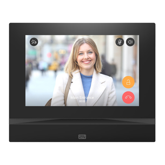
- Page 119 2N® Indoor View User Manual Status and Description User Actions Navigation Actions and Results In Call The display shows the camera view if available, or the called device ID if no camera is available. A timer is running at the view.
- Page 120 2N® Indoor View User Manual Status and Description User Actions Navigation Actions and Results Save camera The snapshot is saved in Press the snapshot manually the call log detail. The log button to save can contain several the snapshot snapshots.
- Page 121 2N® Indoor View User Manual Status and Description User Actions Navigation Actions and Results Increase and The call volume is Press the decrease call increased or decreased by button and the volume one level by each press of + −...
- Page 122 2N® Indoor View User Manual Status and Description User Actions Navigation Actions and Results Do Not Disturb The device is in the basic relax status. The doorbell icon is red. Mode Display Directory Press the blue The list of all available backlit phone devices is displayed.
- Page 123 2N® Indoor View User Manual Status and Description User Actions Navigation Actions and Results Doorbell Ringing The doorbell ringing information is displayed on the background of other operation states. The display shows the camera preview if available. If a call is active simultaneously, a green bar is displayed in the upper screen that enables you to return to the call.
-
Page 124: Maintenance - Cleaning
2N® Indoor View User Manual 6. Maintenance – Cleaning If used frequently, the device surface gets dirty. Use a piece of soft cloth moistened with clean water to clean the device. You are recommended to follow the principles below while cleaning: Do not use aggressive detergents (such as abrasives or strong disinfectants). -
Page 125: Technical Parameters
2N® Indoor View User Manual 7. Technical Parameters Power Supply • Type: 12 V DC +/−10 % adapter or PoE 802.3af • Recommended power supply: 12 V / 1 A • Polarity reversal protection: yes Power Consumption • In idle: • 12 V: 2,28 W – 0,19 A •... - Page 126 2N® Indoor View User Manual • Weight: 555 g • Operating temperature: 0 to 50 °C • Relative humidity: 10 to 90 % non-condensing • Storing temperature: −20 to 70 °C • Recommended altitude: 0–2000 m 126 / 132...
-
Page 127: Supplementary Information
2N® Indoor View User Manual 8. Supplementary Information ® This section provides supplementary information on the 2N Indoor View product. Here is what you can find in this section: • 8.1 Troubleshooting • 8.2 Directives, Laws and Regulations – General Instructions and Cautions ... -
Page 128: Troubleshooting
For the most frequently asked questions refer to faq.2n.cz. 8.2 Directives, Laws and Regulations – General Instructions and Cautions ® Indoor View conforms to the following directives and regulations: • 2014/35/EU for electrical equipment designed for use within certain voltage limits •... - Page 129 / device in contradiction to the manufacturer’s instructions, guidelines or recommendations or in conjunction with unsuitable products / devices of other suppliers, the customer agrees that the 2N TELEKOMUNIKACE a.s. company shall not be held liable for any functionality limitation of such a product or any damage, loss or injury related to this potential functionality limitation.
- Page 130 2N® Indoor View User Manual Please read this User Manual carefully before using the product. Follow all instructions and recommendations included herein. Any use of the product that is in contradiction with the instructions provided herein may result in malfunction, damage or destruction of the product.
- Page 131 2N® Indoor View User Manual Electric Waste and Used Battery Pack Handling Do not place used electric devices and battery packs into municipal waste containers. An undue disposal thereof might impair the environment! Deliver your expired electric appliances and battery packs removed from them to dedicated dumpsites or containers or give them back to the dealer or manufacturer for environmental- friendly disposal.
- Page 132 2N® Indoor View User Manual 132 / 132...
Need help?
Do you have a question about the Indoor View and is the answer not in the manual?
Questions and answers