Panasonic HL-G2 Series User Manual
Laser displacement sensor
Hide thumbs
Also See for HL-G2 Series:
- User manual (252 pages) ,
- Specifications (17 pages) ,
- Installation instructions (2 pages)

Related Manuals for Panasonic HL-G2 Series


Summary of Contents for Panasonic HL-G2 Series
- Page 1 Laser Displacement Sensor HL-G2 Series User’s Manual Analog Output Type WUME-HLG2AN-2 2024.4 industry.panasonic.com/...
- Page 2 (MEMO) WUME-HLG2AN-2...
- Page 3 Introduction Thank you for purchasing Laser Displacement Sensor HL-G2 Series. Before using this product, read and understand this User's Manual. Use the product correctly and in the optimum manner. Keep this manual in a safe location for reference whenever necessary.
- Page 4 (MEMO) WUME-HLG2AN-2...
-
Page 5: Table Of Contents
Table of Contents 1 Before Using This Product..............1-1 1.1 Safety Precautions (Always observe) ..........1-2 1.2 Handling Precautions................1-3 1.2.1 Explanation of Graphic Symbols ............1-3 1.2.2 Handling Precautions ............... 1-3 1.3 Terminology..................1-6 1.4 Regulations and Standards ..............1-7 1.5 Conditions for Compliance with CE Marking/UKCA Marking....1-8 1.6 Laser Safety Standards ..............1-9 1.6.1 IEC / EN / JIS / GB / KS .............. - Page 6 4.4.4 Teaching Mode................. 4-36 4.4.5 Tolerance ..................4-38 4.5 Output Setting ..................4-40 4.5.1 Judgment Output ................4-40 4.5.2 Output Delay Timer Selection ............4-42 4.5.3 Output Delay Timer Setting.............. 4-46 4.5.4 Output Type ..................4-47 4.5.5 Analog Output .................. 4-48 4.5.6 Analog Scaling .................
- Page 7 7.2.1 Product..................... 7-10 7.2.2 Optional Cable ................. 7-11 7.2.3 Optional Cable Installation Diagram ..........7-12 Appendix Screen Transition List ............App-1 Screen Transition List ................App-2 WUME-HLG2AN-2...
- Page 8 (MEMO) viii WUME-HLG2AN-2...
-
Page 9: Before Using This Product
1 Before Using This Product 1.1 Safety Precautions (Always observe) ..........1-2 1.2 Handling Precautions................1-3 1.2.1 Explanation of Graphic Symbols ............1-3 1.2.2 Handling Precautions ............... 1-3 1.3 Terminology..................1-6 1.4 Regulations and Standards ..............1-7 1.5 Conditions for Compliance with CE Marking/UKCA Marking....1-8 1.6 Laser Safety Standards ..............1-9 1.6.1 IEC / EN / JIS / GB / KS .............. -
Page 10: Safety Precautions (Always Observe)
1.1 Safety Precautions (Always observe) 1.1 Safety Precautions (Always observe) This section explains important rules that must be observed to prevent personal injury and property damage. ■ Safety precautions items are classified into “WARNING” and “CAUTION” depending on the level of hazard. Risk of death or serious injury. -
Page 11: Handling Precautions
1.2 Handling Precautions 1.2 Handling Precautions 1.2.1 Explanation of Graphic Symbols ■ In this manual, the following symbols are used to indicate safety information that must be observed. Indicates an action that is prohibited or a matter that requires caution. Indicates an action that must be taken. - Page 12 1.2 Handling Precautions • If UKCA marking is required, the Safety Extra Low Voltage (SELV) or Protective Extra Low Voltage (PELV) of the power supply unit must comply with the EMC Regulations. ● When using this product in a positive ground environment, do not mix positive and negative grounds.
- Page 13 1.2 Handling Precautions ● Do not drop or subject this product to strong shocks. Doing so may result in an accident or failure. Other Precautions ● When this product becomes unnecessary, dispose of the product properly as industrial waste in accordance with the applicable law in the country. ●...
-
Page 14: Terminology
1.3 Terminology 1.3 Terminology Term Description A display that allows the user to check the measured distance (measured value) Measurement display between the sensor and the sensing object A value (threshold) that is used to judge if a measure value falls within the HIGH set value / LOW predetermined range. -
Page 15: Regulations And Standards
1.4 Regulations and Standards 1.4 Regulations and Standards ■ Conformity Directives and Conforming Regulations EU Law: EMC Directive 2014/30/EU British Legislation: EMC Regulations 2016/1091 ● Applicable standards • EN 60825-1 • EN 61000-6-2 • EN 61000-6-4 ● US Regulations: FDA21 CFR1040.10, and 1040.11 (Laser Notice No.56 applied) ■... -
Page 16: Conditions For Compliance With Ce Marking/Ukca Marking
1.5 Conditions for Compliance with CE Marking/UKCA Marking 1.5 Conditions for Compliance with CE Marking/UKCA Marking To use this product as a CE marking/UKCA marking compliant product, the following conditions must be met. ● The signal and power lines connected to the product must not exceed the maximum length of the optional cable available. -
Page 17: Laser Safety Standards
1.6 Laser Safety Standards 1.6 Laser Safety Standards 1.6.1 IEC / EN / JIS / GB / KS To prevent laser products from affecting their users, IEC, EN, JIS, GB, and KS standards have the following respective standards: These standards classify laser products into classes according to the hazard level of laser, and prescribe safety and preventive measures that should be implemented for each class. -
Page 18: Fda
1.6 Laser Safety Standards 1.6.2 FDA ■ Exporting to the USA If this product is incorporated into facilities or equipment to be exported to the US, it is subject to the laser regulations of the US Food and Drug Administration (FDA). To prevent laser products from affecting their users, PART1040 (Performance Standards for Light-Emitting Products) was established as one of the FDA regulations. -
Page 19: Contents Of Package
1.7 Contents of Package 1.7 Contents of Package The following accessories are included in the product package. Before using this product, make sure that no items are missing. Products HL-G203B-A-MK / 30 mm type HL-G205B-A-MK / 50 mm type HL-G208B-A-MK / 85 mm type HL-G212B-A-MK / 120 mm type HL-G225B-A-MK / 250 mm type ●... - Page 20 (MEMO) 1-12 WUME-HLG2AN-2...
-
Page 21: System Configuration
2 System Configuration 2.1 System Configuration Diagram ............2-2 2.2 Description of Parts................2-3 WUME-HLG2AN-2... -
Page 22: System Configuration Diagram
2.1 System Configuration Diagram 2.1 System Configuration Diagram The following shows a system configuration and the optional cable used to connect devices. WUME-HLG2AN-2... -
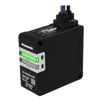
Page 23: Description Of Parts
2.2 Description of Parts 2.2 Description of Parts ■ Sensor unit Name Function Lit in green while laser beams are being emitted. Laser radiation indicator It blinks if an error occurs. Lit in orange when an measurement alarm occurs. Alarm indicator It blinks if an error occurs. - Page 24 2.2 Description of Parts ■ Operation/display section Name Function Display section (Note 1) Displays measured values, settings, and error codes Cable connector part Used when connecting the sensor with a optional cable. UP (DOWN) key ENTER key Used to change setting items and settings when configuring settings. DOWN (UP) key (Note 1) For error messages and actions to be taken, refer to...
- Page 25 2.2 Description of Parts ■ Measurement display Name Function Measurement value display The current measured value (mm) is displayed with a sign. LASER icon Displayed when the laser is turned on. Displayed depending on the state of the measured value judgment result. When the measured value exceeds the HIGH set value, "HI"...
- Page 26 2.2 Description of Parts ● The display range of measured values for each distance type is as follows. Measurement Measurement center Model name (Note 2) Display range distance (Note 1) range HL-G203B-A-MK 30 mm ±5 mm -9.5000 to +9.5000 HL-G205B-A-MK 50 mm ±10 mm -95.000 to +95.000...
- Page 27 2.2 Description of Parts ■ Setting screen (Setting mode) Name Function Shows the setting item by number. Hold down the "ENTER" key for 2 seconds on the measurement display. The screen that appears after entering the Setting mode is the first level. Menu number Following this, pressing the "ENTER"...
- Page 28 2.2 Description of Parts Hierarchical level Menu display bar Setting item Reference page number (Number of bars) Hysteresis "4.4.3 Hysteresis" Teaching Mode "4.4.4 Teaching Mode" Tolerance "4.4.5 Tolerance" Judgement Output "4.5.1 Judgment Output" Output Delay Timer Output Type "4.5.4 Output Type" Analog Output "4.5.5 Analog Output"...
-
Page 29: Installation And Setup
3 Installation and Setup 3.1 Flow of Operations up to Measurement Startup .........3-2 3.2 Sensor Installation ................3-3 3.3 Sensor Installation Direction and Angle ..........3-4 3.4 Optional Cable Connection Method ............3-7 3.5 Functions and Wiring of I/O Lines............3-9 3.5.1 Grounding ..................3-12 3.5.2 Precautions for positive ground environment........ -
Page 30: Flow Of Operations Up To Measurement Startup
3.1 Flow of Operations up to Measurement Startup 3.1 Flow of Operations up to Measurement Startup This section explains the flow of operations up to measurement startup by using workpiece detection mode as an example. Before power ON Check package contents and confirm that all parts are complete. Installation and wiring Install this product and connect theoptional cables according to the installation and wiring methods. -
Page 31: Sensor Installation
3.2 Sensor Installation 3.2 Sensor Installation When installing this product, use M4 captive washer screws (to be prepared separately). (Tightening torque: 0.8 N∙m or less) ● Carefully handle the sensor so that no force is applied around the connector of the optional cable. -
Page 32: Sensor Installation Direction And Angle
3.3 Sensor Installation Direction and Angle 3.3 Sensor Installation Direction and Angle To stabilize measurement (including the reduction of measurement errors), install the sensor considering the installation direction depending on the operating environment. Install the sensor so that the beam emitting part and beam receiving part surfaces are set in parallel with the measurement object. - Page 33 3.3 Sensor Installation Direction and Angle ● When the measurement object rotates To measure rotating objects, installing the sensor as shown in the figure below minimizes the effects of vertical vibration, misalignment, etc. ● When there are level differences on the surface of the measurement object To measure moving objects with level differences on the surface, installing the sensor as shown in the figure below minimizes the effect of the level edges.
- Page 34 3.3 Sensor Installation Direction and Angle ■ Installation Angle Install the sensor so that the beam emitting part and beam receiving part surfaces are set at 90 degrees (parallel) with the measurement object. <Reference> Model name Measurement center distance Measurement range HL-G203B-A-MK 30 mm ±5 mm...
-
Page 35: Optional Cable Connection Method
3.4 Optional Cable Connection Method 3.4 Optional Cable Connection Method ● When using the optional cable, confirm that there is no foreign matters in the connector part before using the cable. ● Always grasp the connector body when connecting or disconnecting the connector. Wires may break if excessive stress is applied to the cable. - Page 36 3.4 Optional Cable Connection Method WUME-HLG2AN-2...
-
Page 37: Functions And Wiring Of I/O Lines
3.5 Functions and Wiring of I/O Lines 3.5 Functions and Wiring of I/O Lines ● Before wiring, always turn the power OFF. ● Be sure to use the specified optional cables. ● Be sure to insulate the ends of leads that are not used. ■... - Page 38 3.5 Functions and Wiring of I/O Lines ■ I/O circuit diagram When PNP is set (Note 1) This product operates as a normal PNP input sensor according to the PNP input specifications. However, due to the effect of the NPN/PNP switching circuit, 3.3 V is applied from the input to the outside when PNP is set.
- Page 39 3.5 Functions and Wiring of I/O Lines When NPN is set WUME-HLG2AN-2 3-11...
-
Page 40: Grounding
3.5 Functions and Wiring of I/O Lines Analog output circuit (Note 1) The 0 V and analog GND terminals of this product are internally connected. If there is a potential difference between the sensor unit power supply (0 V) and the GND of the analog input device power supply, an overcurrent may flow between the 0 V and the AGND, causing a failure. -
Page 41: Precautions For Positive Ground Environment
3.5 Functions and Wiring of I/O Lines 3.5.2 Precautions for positive ground environment The 0 V and analog GND terminals of this product are internally connected. Connecting the product to a PC or other device in which the F.G. and GND are internally connected may cause a short circuit in the power supply (24 VDC) through the PC or analog GND, resulting in a failure. -
Page 42: Initial Startup Settings
3.6 Initial Startup Settings 3.6 Initial Startup Settings ■ Overview After turning on the power supply for the first time or executing "Set value initialization", perform the language, NPN/PNP, and analog output settings. When the power supply is turned on, the startup screen is displayed for two seconds and then the language setting screen is displayed. -
Page 43: Description Of Functions
4 Description of Functions 4.1 List of Functions..................4-3 4.2 Bank Switching ...................4-6 4.3 Sensing Setting...................4-8 4.3.1 Sampling Frequency ................ 4-8 4.3.2 Average Times ................. 4-10 4.3.3 Brightness Tuning ................4-13 4.3.4 Hold Mode..................4-16 4.3.5 Inversion of Measured Value............4-20 4.3.6 Span.................... - Page 44 4 Description of Functions 4.9 1 point/2 points/3 points Teaching ............4-77 4.9.1 1 point Teaching ................4-78 4.9.2 2 points Teaching ................4-82 4.9.3 3 points Teaching ................4-85 4.10 Zero Setting ..................4-89 4.11 Measured Value Resetting ..............4-91 4.12 Key Lock ...................4-92 4.12.1 Key Lock Setting ................
-
Page 45: List Of Functions
4.1 List of Functions 4.1 List of Functions The items that can be set on the measurement display are as follows. ■ Received light intensity monitor Setting item Display section Description of function Reference page Measuremen t display Received The peak intensity of received light (range: 0 light intensity to 1023) of the received light waveform. -
Page 46: List Of Functions
4.1 List of Functions ■ Zero setting ON / Zero setting OFF Setting item Display Description of function Reference section page Measurement display Zero setting ON This function is used to forcibly set the "4.10 Zero measured value to "0". You can use Setting"... - Page 47 4.1 List of Functions ■ Setting mode Setting item Display Description of function Reference section page Measurement display Bank switching Used to switch over the bank to be "4.2 Bank used. Switching" Sensing setting This is a function setting that is used to "4.3 Sensing control the received light intensity of Setting"...
-
Page 48: Bank Switching
4.2 Bank Switching 4.2 Bank Switching ■ Overview This product has four banks, Bank 1 to Bank 4, in order to hold some setting values. By switching the bank to use, you can easily apply the settings when needed depending on the measurement object. - Page 49 4.2 Bank Switching Setting item Set value Default value Bank Bank 1 Bank 1 Bank 2 Bank 3 Bank 4 ■ Types of setting items read from banks Major setting item Setting item Sensing setting Sampling frequency Average times Brightness tuning Hold mode Span Offset...
-
Page 50: Sensing Setting
4.3 Sensing Setting 4.3 Sensing Setting ■ Overview This is a function setting that is used to control the received light intensity of this product and perform calculations on the output measurement values to ensure accurate and stable measurement. 4.3.1 Sampling Frequency ■... - Page 51 4.3 Sensing Setting Setting item Set value Default value 100 μs 200 μs Sampling Frequency 500 μs 1 ms 1 ms 2 ms WUME-HLG2AN-2...
-
Page 52: Average Times
4.3 Sensing Setting 4.3.2 Average Times ■ Overview Set the number of moving averages used to calculate measured values. This setting is used to stabilize fluctuating measured values. When the average count is set to 4 (Sampling cycle: 1 ms) ■... - Page 53 4.3 Sensing Setting ● Hold down the <ENTER> key for 2 seconds on the setting screen, and the setting change is suspended and the screen returns to the previous display. WUME-HLG2AN-2 4-11...
- Page 54 4.3 Sensing Setting Setting item Set value Default value Average Times 1024 4-12 WUME-HLG2AN-2...
-
Page 55: Brightness Tuning
4.3 Sensing Setting 4.3.3 Brightness Tuning ■ Overview Depending on the workpiece to be measured, you can change the beam brightness adjustment method. When measuring two workpieces with large brightness difference, use the brightness tuning which may stabilize the measurement accuracy. To select the brightness tuning, sensing objects with different brightness are required. - Page 56 4.3 Sensing Setting ■ Brightness Tuning Procedure When selecting Brightness tuning, both the bright portion and dark portion of the sensing object need to be registered in this product in advance. Follow the procedure below to configure the settings. Prepare two workpieces with different brightness and turn ON Brightness Tuning. Confirm that a message saying"Set 1st Target - Push ENTER SW"is displayed on the display section and then set the 1st workpiece and press the<ENTER>key.
- Page 57 4.3 Sensing Setting ● In the following case, teaching cannot be started. • Hold mode is set to other than "None (Normal mode)". ● In the following cases, Brightness Tuning will fail. • Alarm state • Indeterminate state • Hold state (In this case, the state changes to indeterminate state after execution of tuning.) •...
-
Page 58: Hold Mode
4.3 Sensing Setting 4.3.4 Hold Mode ■ Overview Set a method to hold the measured value according to the measuring method of sensing objects. ■ Setting method The following describes a method to hold the measured value using an external trigger input. When "None (Normal mode)"... - Page 59 4.3 Sensing Setting None (Normal mode) When the trigger input turns ON, the measured value is held. When the trigger input turns OFF, the hold state is released, and the value is updated and output as necessary. Peak Hold Used to update and output the maximum value of the measured values as needed. During the period from when the trigger input turns ON to when it turns OFF, the maximum value data is held.
- Page 60 4.3 Sensing Setting Bottom Hold Used to update and output the minimum value of the measured values as needed. During the period from when the trigger input turns ON to when it turns OFF, the minimum value data is held. Peak to Peak Hold Used to update and output the value obtained by subtracting the minimum value from the maximum value as needed.
- Page 61 4.3 Sensing Setting ● In the following cases, the held value is initialized. • When the trigger input is turned OFF • When Measured value resetting is executed • When a setting change is made to cause the measured value to be in an indeterminate state •...
-
Page 62: Inversion Of Measured Value
4.3 Sensing Setting 4.3.5 Inversion of Measured Value ■ Overview This is a function that reverses the positive / negative direction of the measured value. When set to "Reverse", only the positive/negative sign of the measured value is reversed. ■ Setting method 4-20 WUME-HLG2AN-2... - Page 63 4.3 Sensing Setting ● When set to "Normal", the measured value increases as the workpiece comes closer to this product. ● When set to "Reverse", the measured value decreases as the workpiece comes closer to this product. ● For the HIGH and LOW measurement values and the zero set correction value, changing the Inversion of Measured Value setting does not change the positive/negative sign.
-
Page 64: Span
4.3 Sensing Setting 4.3.6 Span ■ Overview This is a function that multiplies a span (factor) to the measured value after zero setting and outputs the result. By adding an optionally set value as the offset, the value is output as the final measured value. Final measured value = Span (factor) ×... - Page 65 4.3 Sensing Setting ● The set value can be set in increments of 0.0001. ● Simultaneously pressing the <UP> and <DOWN> keys while moving between the digits returns to the first digit. ● Hold down the <ENTER> key for 2 seconds on the setting screen, and the setting change is suspended and the screen returns to the previous display.
-
Page 66: Offset
4.3 Sensing Setting 4.3.7 Offset ■ Overview This function is used to add or subtract an optional value to/from the measured value. By multiplying a span (factor) to the measured value after zero setting and by adding an optionally set value as the offset, the value is output as the final measured value. Final measured value = Span (factor) ×... - Page 67 4.3 Sensing Setting ● The setting range varies depending on the distance type of this product. ● Simultaneously pressing the <UP> and <DOWN> keys while moving between the digits returns to the first digit (sign). ● Hold down the <ENTER> key for 2 seconds on the setting screen, and the setting change is suspended and the screen returns to the previous display.
-
Page 68: Judgment Setting
4.4 Judgment Setting 4.4 Judgment Setting ■ Overview This is a function setting related to judgment results of the measured value. 4.4.1 HIGH Set Value ■ Overview This function allows you to optionally set the upper limit value (HIGH set value) used to judge the measured value. - Page 69 4.4 Judgment Setting Setting item Distance type Set value (mm) Default value (mm) Setting resolution (μm) HIGH set value 30 mm -9.5000 to +5.0000 +9.5000 50 mm -95.000 to +10.000 +95.000 85 mm +20.000 120 mm +30.000 250 mm -950.00 to +150.00 +950.00 WUME-HLG2AN-2...
- Page 70 4.4 Judgment Setting Setting a"HIGH set value"directly during measurement ■ Overview In addition to the method described in HIGH Set Value, you can also set a HIGH set value directly from the measurement display during measurement. Press the <UP> key in the measurement display, and HIGH set value is displayed at the top of the display and a set threshold value is displayed at the bottom.
- Page 71 4.4 Judgment Setting ● Simultaneously pressing the <UP> and <DOWN> keys while moving between the digits returns to the first digit (sign). WUME-HLG2AN-2 4-29...
-
Page 72: Low Set Value
4.4 Judgment Setting 4.4.2 LOW Set Value ■ Overview This function allows you to optionally set the lower limit value (LOW set value) used to judge the measured value. If the measured value falls below the LOW set value, the judgment is output as LOW. ■... - Page 73 4.4 Judgment Setting Setting item Distance type Set value (mm) Default value (mm) Setting resolution (μm) LOW set value 30 mm -9.5000 to -5.0000 +9.5000 50 mm -95.000 to -10.000 +95.000 85 mm -20.000 120 mm -30.000 250 mm -950.00 to -150.00 +950.00 WUME-HLG2AN-2...
- Page 74 4.4 Judgment Setting Setting a"LOW set value"directly during measurement ■ Overview In addition to the method described in LOW Set Value, you can also set a LOW set value directly from the measurement display during measurement. Press the <DOWN> key in the measurement display, and LOW set value is displayed at the top of the display and a set value is displayed at the bottom.
- Page 75 4.4 Judgment Setting ● Simultaneously pressing the <UP> and <DOWN> keys while moving between the digits returns to the first digit (sign). WUME-HLG2AN-2 4-33...
-
Page 76: Hysteresis
4.4 Judgment Setting 4.4.3 Hysteresis ■ Overview If the sensing object vibrates in the vicinity of the HIGH set value / LOW set value, the final measured value may fluctuate, resulting in unstable operation. When a sensing workpiece is located near the HIGH set value / LOW set value, increasing the value of hysteresis makes output operations stable. - Page 77 4.4 Judgment Setting ● The hysteresis setting range varies depending on the distance type of this product. ● Simultaneously pressing the <UP> and <DOWN> keys while moving between the digits returns to the first digit. ● Hold down the<ENTER>key for 2 seconds on the setting screen, and the setting change is suspended and the screen returns to the previous display.
-
Page 78: Teaching Mode
4.4 Judgment Setting 4.4.4 Teaching Mode ■ Overview By teaching using a sensing object, you can automatically set HIGH and LOW set values. You can select the teaching method from one of the following three types. Set value Operation Reference page 1 point teaching This method is to perform 1-point teaching on the "4.9.1 1 point Teaching"... - Page 79 4.4 Judgment Setting Setting item Set value Default value Teaching Mode 1 point 1 point 2 points 3 points ● Hold down the <ENTER> key for 2 seconds on the setting screen, and the setting change is suspended and the screen returns to the previous display. WUME-HLG2AN-2 4-37...
-
Page 80: Tolerance
4.4 Judgment Setting 4.4.5 Tolerance ■ Overview When 1-point teaching is performed, the measured value of the master workpiece plus the tolerance can be set as the HIGH set value and the measured value of the master workpiece minus the tolerance can be set as the LOW set value. This is valid only when 1-point teaching is set. - Page 81 4.4 Judgment Setting ● You cannot set this to a value that is equal to or less than the hysteresis. ● Hysteresis can be set regardless of the tolerance value. Depending on the set value, 1-point teaching may fail. ● Simultaneously pressing the <UP> and <DOWN> keys while moving between the digits returns to the first digit.
-
Page 82: Output Setting
4.5 Output Setting 4.5 Output Setting ■ Overview This is a function setting related to output operation. 4.5.1 Judgment Output This function allows you to select a combination of signals to be output from external OUT1, OUT2, and OUT3 from four types. This product is equipped with an alarm signal output function. - Page 83 4.5 Output Setting ■ Setting method Setting item Set value Default value 3-State Logic Judgment output 3-State Independent 2-State ● Hold down the ENTER key for 2 seconds on the setting screen, and the setting change is suspended and the screen returns to the previous display. WUME-HLG2AN-2 4-41...
-
Page 84: Output Delay Timer Selection
4.5 Output Setting 4.5.2 Output Delay Timer Selection ■ Overview This setting is used to set the timing from ON to OFF or from OFF to ON for the measured value judgment result (HIGH / GO/ LOW). Set value Operation OFF (No timer) No change is made in the timing for the measured value judgment result. - Page 85 4.5 Output Setting Setting item Set value Default value OFF (No timer) On Delay Timer selection Off Delay OFF (No timer) One Shot Hold OFF (No timer) When set to"OFF (No timer)", the measured value judgment result will be as shown in the following diagram.
- Page 86 4.5 Output Setting Off Delay When set to "Off Delay", the output will be delayed for the timer’s time from the time when the judgment result is turned OFF. If the OFF duration is less than the timer’s time, the delay does not appear in the measured value judgment result.
- Page 87 4.5 Output Setting WUME-HLG2AN-2 4-45...
-
Page 88: Output Delay Timer Setting
4.5 Output Setting 4.5.3 Output Delay Timer Setting ■ Overview This setting is used to set the delay time in milliseconds for the output delay timer selected in "4.5.2 Output Delay Timer Selection". ■ Setting method ● The output delay timer setting is reflected only when "Off Delay", "On Delay", or "One Shot" is selected in Output delay timer selection. -
Page 89: Output Type
4.5 Output Setting 4.5.4 Output Type This function allows you to select the operation of judgment output. Set value Operation Normally open (N.O.) Outputs ON when judgment output is ON. Normally closed (N.C.) Outputs OFF when judgment output is ON. Example of output type settings (for GO output) ■... -
Page 90: Analog Output
4.5 Output Setting 4.5.5 Analog Output This function allows you to select the output operation of analog output, which is OFF, Voltage, or Current. Normal Indetermi Alarm Error Output Operation description output nate output operation range value Turns OFF the analog output function. 0 mA/0 V 0 mA/0 V 0 mA/0 V... -
Page 91: Analog Scaling
4.5 Output Setting 4.5.6 Analog Scaling ■ Overview This function allows you to scale analog current output or analog voltage output to any value. By setting optional two points as measured value “A” and measured value “B”, the values of those optional points can be scaled to analog current output “a”... - Page 92 4.5 Output Setting (Note 1) If "Voltage" is selected in Analog Output, this item is not displayed. Item Display section Setting range (V) Default value (V) 0.000 to 5.000 0.000 (Note 1) Voltage a 5.000 (Note 1) Voltage b (Note 1) If "Current"...
- Page 93 4.5 Output Setting Current value setting Voltage value setting ● When changing the settings in Analog Output and Analog Scaling, the analog output remains OFF or indeterminate state for a fixed period and the output value may not change as set depending on the timing.
-
Page 94: Input Setting
4.6 Input Setting 4.6 Input Setting ■ Overview This is a function setting related to input operation. 4.6.1 Input Line Operation Selection This function allows you to select a combination of signals to be input to external IN1, IN2, and IN3 from five types. - Page 95 4.6 Input Setting ● For I/O circuit diagrams of this product, refer to "I/O circuit diagram". ■ Setting method Setting item Set value Default value Trg/Zero/Reset (Trigger / Zero setting / Measured value resetting) Trg/Zero/Laser (Trigger / Zero setting / Laser stop) Input line operation Trg/Zero/Reset selection...
- Page 96 4.6 Input Setting Input line operation ■ Minimum input time The minimum input time and standby time differ according to the input type. Zero setting input Measured value resetting input 4-54 WUME-HLG2AN-2...
- Page 97 4.6 Input Setting Trigger input ● Trigger input by "IN1 (trigger input)" on the Input line must be continued for at least 2 Bank A / Bank B input When “Bank A/B” (using 2 lines) is assigned to the input line function, input operations are as follows.
- Page 98 4.6 Input Setting 5. If Bank A changes from ON to OFF within the bank switching prohibition time (50 ms) after switching to Bank 4 in step 2, the bank is switched to Bank 3 when the bank switching prohibition time and the bank switching delay time have elapsed. 4-56 WUME-HLG2AN-2...
- Page 99 4.6 Input Setting Laser stop input Teaching input WUME-HLG2AN-2 4-57...
-
Page 100: Laser Stop
4.6 Input Setting 4.6.2 Laser Stop ■ Overview This is a function that switches ON and OFF the laser emission. When the setting is OFF, laser will be emitted. When it is ON, laser emission will be stopped. ■ Setting method ●... -
Page 101: Trigger Mode
4.6 Input Setting 4.6.3 Trigger Mode The following describes a method to hold the final measured value using a trigger input. This mode can be selected from the following two types: "Hold" or "One Shot". ■ Hold If trigger input turns ON, this function holds the final measured value while the input is ON. ■... - Page 102 4.6 Input Setting ■ Setting method ● Trigger mode can be set to "One Shot" only when "None (Normal mode)" is selected in Hold mode. ● The hold releasing conditions are as follows. • When a setting change is made to cause the measured value to be in an indeterminate state •...
-
Page 103: Input Line Saving Setting
4.6 Input Setting 4.6.4 Input Line Saving Setting ■ Overview The set values changed by the function selected in Input line operation selection will not normally be saved. However, when this function is set to ON, the zero setting (ON/OFF) and the HIGH set value / LOW set value by teaching will be saved. -
Page 104: Alarm Setting
4.7 Alarm Setting 4.7 Alarm Setting ■ Overview The alarm setting provides function settings related to data processing in an unmeasurable state. Unmeasurable state refers to a state where the light receiving waveform of CMOS does not allow for correct calculation of measured values. The types of unmeasurable states are as shown below. -
Page 105: Alarm Delay Count
4.7 Alarm Setting 4.7.1 Alarm Delay Count ■ Overview You will be notified of an alarm if an unmeasurable state is detected. This function allows you to delay the notification until the set sampling count is reached. While an alarm is being delayed, the last measured value is held. -
Page 106: Alarm Analog Output
4.7 Alarm Setting 4.7.2 Alarm Analog Output ■ Overview This function allows you to set the analog output operation (analog output value) at alarm occurrence. An alarm will be output if an unmeasurable state continues for more than the sampling count set in "4.7.1 Alarm Delay Count". - Page 107 4.7 Alarm Setting ● When changing the setting in Alarm analog output, analog output remains OFF or indeterminate state for a fixed period and the output value may not change as set depending on the timing. ● Hold down the <ENTER> key for 2 seconds on the setting screen, and the setting change is suspended and the screen returns to the previous display.
-
Page 108: Alarm Digital Output
4.7 Alarm Setting 4.7.3 Alarm Digital Output ■ Overview This function allows you to set the digital output operation at alarm occurrence (measured value display, measured value reference by communication). An alarm will be output if an unmeasurable state continues for more than the sampling count set in "4.7.1 Alarm Delay Count". - Page 109 4.7 Alarm Setting Displa 3-value Logic Independence 2-value sectio – ---- Output type: Normally closed (N.C.) Displa 3-value Logic Independence 2-value sectio HIGH set Measur value < Measured value value LOW set Measur value ≤ Measured value value ≤ HIGH set value Measured Measur...
- Page 110 4.7 Alarm Setting ■ Setting method ● Hold down the <ENTER> key for 2 seconds on the setting screen, and the setting change is suspended and the screen returns to the previous display. Setting item Set value Default value Alarm digital output Hold Hold Alarm...
-
Page 111: System Setting
4.8 System Setting 4.8 System Setting ■ Overview This is a function setting related to the system settings such as initialization and display language. 4.8.1 Display Digit ■ Overview This function allows you to switch the number of digits after the decimal point in the digital display. - Page 112 4.8 System Setting ● Any numbers after the specified number of digits displayed are rounded down. ● Teaching may fail or errors may occur in measured value judgment results or calculation results due to the digits after the decimal point that are not displayed depending on the product type or settings.
-
Page 113: Eco Mode
4.8 System Setting 4.8.2 ECO Mode ■ Overview By setting the Eco mode to ON to turn OFF the display section except when operating the product, you can extend the life of the display section. If the Eco mode is set to ON, the display section will turn OFF when no key is operated for 180 seconds. -
Page 114: Display Inversion
4.8 System Setting 4.8.3 Display Inversion ■ Overview The display on the display section is displayed upside down. ■ Setting method ● Hold down the <ENTER> key for 2 seconds on the setting screen, and the setting change is suspended and the screen returns to the previous display. Setting item Set value Default value... -
Page 115: Language Setting
4.8 System Setting 4.8.4 Language Setting ■ Overview This function allows you to change the language to be displayed on the display section. ■ Setting method ● Hold down the<ENTER>key for 2 seconds on the setting screen, and the setting change is suspended and the screen returns to the previous display. -
Page 116: Settings Initialization
4.8 System Setting 4.8.5 Settings Initialization ■ Overview This function allows you to initialize each setting. Initialization method Operation Bank1 Initializes the settings of Bank 1. Bank2 Initializes the settings of Bank 2. Bank3 Initializes the settings of Bank 3. Bank4 Initializes the settings of Bank 4. - Page 117 4.8 System Setting Specified Bank/ Major setting Set value Setting item All Areas item initialization ALL Bank Alarm Analog Output ○ ○ ○ Alarm setting Alarm Digital Output ○ ○ ○ Alarm Delay Count ○ ○ ○ Display Digit ○ ○...
- Page 118 4.8 System Setting ● Priority is given to initialization if any key operation or external input is performed while initialization is being executed. ● Hold down the <ENTER> key for 2 seconds on the setting screen, and the setting change is suspended and the screen returns to the previous display.
-
Page 119: Point/2 Points/3 Points Teaching
4.9 1 point/2 points/3 points Teaching 4.9 1 point/2 points/3 points Teaching ■ Overview This method is used to set the HIGH set value and LOW set value using one or more sensing objects. ● When performing teaching, it is necessary to set a teaching type in advance. For details on setting the teaching type, refer to "4.4.4 Teaching Mode". -
Page 120: Point Teaching
4.9 1 point/2 points/3 points Teaching 4.9.1 1 point Teaching ■ Overview This method is to perform teaching on sensing objects and set the value obtained by adding the tolerance to the teaching result as the HIGH set value and the value obtained by subtracting the tolerance from the teaching result as the LOW set value. - Page 121 4.9 1 point/2 points/3 points Teaching Press the<ENTER>key. Teaching will be executed. When teaching is completed, "Success" is displayed on the display section. Then, the newly set HIGH set value and LOW set value are displayed in sequence, and the display returns to the measurement display.
- Page 122 4.9 1 point/2 points/3 points Teaching 4-80 WUME-HLG2AN-2...
- Page 123 4.9 1 point/2 points/3 points Teaching 1 point teaching using external inputs This section describes how to execute 1-point teaching using external inputs. ● You need to set "Input line operation selection" in advance. For how to set "Input line operation selection", refer to "4.6.1 Input Line Operation Selection".
-
Page 124: Points Teaching
4.9 1 point/2 points/3 points Teaching 4.9.2 2 points Teaching ■ Overview Measure two workpieces and set the higher final measured value to the HIGH set value and the lower final measured value to the LOW set value. Set Teaching type to "2 points teaching". On the measurement display, insert the 1st sensing object. - Page 125 4.9 1 point/2 points/3 points Teaching With the 2nd sensing object inserted, press the<ENTER>key. Teaching for the 2nd point is executed. When teaching is completed,"Success"is displayed on the display section. Then, the newly set HIGH set value and LOW set value are displayed in sequence, and the display returns to the measurement display.
- Page 126 4.9 1 point/2 points/3 points Teaching 2 points teaching using external inputs This section describes how to execute 2 points teaching using external inputs. ● You need to set "Input line operation selection" in advance. For how to set "Input line operation selection", refer to "4.6.1 Input Line Operation Selection".
-
Page 127: Points Teaching
4.9 1 point/2 points/3 points Teaching 4.9.3 3 points Teaching ■ Overview This method is to perform teaching on three sensing objects and set the HIGH set value and LOW set value for each of them based on the measured results. Among the three measured values, the highest value is the maximum value, the second highest value is the median value, and the third highest value is the minimum value. - Page 128 4.9 1 point/2 points/3 points Teaching Confirm that a message saying"Set 2nd Target and Push ENTER SW"is displayed at the top of the display. The display changes to the 2nd point input screen. With the 2nd sensing object inserted, press the<ENTER>key. Teaching for the 2nd point is executed.
- Page 129 4.9 1 point/2 points/3 points Teaching If the sensing object is not detected stably, for example, if two or more of the three teaching points have the same measurement value,"Failed"will be displayed. Re-examine positional relationship among the sensing objects and perform teaching again. WUME-HLG2AN-2 4-87...
- Page 130 4.9 1 point/2 points/3 points Teaching 3 points teaching using external inputs This section describes how to execute 3 points teaching using external inputs. ● You need to set "Input line operation selection" in advance. For how to set "Input line operation selection", refer to "4.6.1 Input Line Operation Selection".
-
Page 131: Zero Setting
4.10 Zero Setting 4.10 Zero Setting ■ Overview This function is used to forcibly set the measured value to "0". You can use the function to adjust the reference point when this product has been replaced or when the workpiece has been changed. - Page 132 4.10 Zero Setting ● If you execute Inversion of Measured Value in the state where zero set setting is complete and the measured value is set to 0, the measured value changes from 0. After executing Inversion of Measured Value, make an adjustment again. ●...
-
Page 133: Measured Value Resetting
4.11 Measured Value Resetting 4.11 Measured Value Resetting ■ Overview This function is used to reset the moving average data of the measured value or the value held by the hold function. Simultaneously hold down the<UP>and<ENTER>keys on the measurement display to reset the measured value. -
Page 134: Key Lock
4.12 Key Lock 4.12 Key Lock This function is used to disable key operation to prevent the conditions set in each setting mode from being changed by mistake. While the key lock setting is activated, all key operations other than key lock release cannot be performed. -
Page 135: Maintenance
5 Maintenance 5.1 Maintenance and Inspection ...............5-2 5.1.1 Maintenance Precautions ..............5-2 5.1.2 Main Inspection Items ..............5-2 WUME-HLG2AN-2... -
Page 136: Maintenance And Inspection
5.1 Maintenance and Inspection 5.1 Maintenance and Inspection 5.1.1 Maintenance Precautions ● When cleaning, be sure to turn off the power supply to do cleaning while the laser radiation is stopped. ● Never use thinner, benzene, or other organic solvents to wipe off dirt or dust because some parts are resin-molded. -
Page 137: Troubleshooting
6 Troubleshooting 6.1 Solutions to Problems .................6-2 6.2 Error Messages and Action Methods..........6-4 WUME-HLG2AN-2... -
Page 138: Solutions To Problems
6.1 Solutions to Problems 6.1 Solutions to Problems Solutions to frequently encountered problems and errors are described below. ● Check the wiring. ● Check if the NPN/PNP setting is correct. ● Check the voltage and capacity of the power supply. Reference Symptom Cause... - Page 139 6.1 Solutions to Problems Reference Symptom Cause Action method page Wiring of I/O Lines" Analog scaling is not set "4.5.6 Anal Set analog scaling correctly. correctly. og Scaling" This product is installed in a Measured values location subject to severe Take measures against vibration.
-
Page 140: Error Messages And Action Methods
6.2 Error Messages and Action Methods 6.2 Error Messages and Action Methods If an error occurs during setting or measurement, one of the error codes listed below will be displayed on the display section. Error code Description Action method Dark level adjustment error Install the sensor so that strong light or E100** fluctuating light does not enter the sensor, and... -
Page 141: Specifications And Dimensions
7 Specifications and Dimensions 7.1 Specifications..................7-2 7.1.1 Beam Diameter ................7-5 7.1.2 Mutual Interference Area ..............7-6 7.2 Shapes and Dimensions ..............7-10 7.2.1 Product..................... 7-10 7.2.2 Optional Cable ................. 7-11 7.2.3 Optional Cable Installation Diagram ..........7-12 WUME-HLG2AN-2... -
Page 142: Specifications
7.1 Specifications 7.1 Specifications Model name HL-G203B-A- HL-G205B-A- HL-G208B-A- HL-G212B-A- HL-G225B-A- Measurement 30 mm 50 mm 85 mm 120 mm 250 mm center distance Measurement range ±5 mm ±10 mm ±20 mm ±30 mm ±150 mm X axis: approx. X axis: approx. X axis: approx. - Page 143 7.1 Specifications Model name HL-G203B-A- HL-G205B-A- HL-G208B-A- HL-G212B-A- HL-G225B-A- †2 This refers to the repeatability of analog output only. Static resolution and linearity error by measurement will be added. † 3 This refers to the linearity of analog output only. Static resolution and linearity error by measurement will be added.
- Page 144 7.1 Specifications Model name HL-G203B-A- HL-G205B-A- HL-G208B-A- HL-G212B-A- HL-G225B-A- Insulation 20 MΩ or higher, using 500 VDC megger resistance Vibration resistance Durability: 10 Hz to 55 Hz (cycle: 1 minute) with 1.5 mm double amplitude in X, Y, and Z directions for 2 hours each Shock resistance 500 m/s...
-
Page 145: Beam Diameter
7.1 Specifications 7.1.1 Beam Diameter WUME-HLG2AN-2... -
Page 146: Mutual Interference Area
7.1 Specifications 7.1.2 Mutual Interference Area When two or more units of this product are installed side by side, no mutual interference will occur as long as the laser spots of the other units are outside the shaded area shown in the figure below. - Page 147 7.1 Specifications ■ 85 mm type (HL-G208B-A-MK) Unit: mm WUME-HLG2AN-2...
- Page 148 7.1 Specifications ■ 120 mm type (HL-G212B-A-MK) Unit: mm WUME-HLG2AN-2...
- Page 149 7.1 Specifications ■ 250 mm type (HL-G225B-A-MK) Unit: mm WUME-HLG2AN-2...
-
Page 150: Shapes And Dimensions
7.2 Shapes and Dimensions 7.2 Shapes and Dimensions 7.2.1 Product HL-G2□□B-A-MK Unit: mm 7-10 WUME-HLG2AN-2... -
Page 151: Optional Cable
7.2 Shapes and Dimensions 7.2.2 Optional Cable CN-8A-C□ (For Analog output) Unit: mm WUME-HLG2AN-2 7-11... -
Page 152: Optional Cable Installation Diagram
7.2 Shapes and Dimensions 7.2.3 Optional Cable Installation Diagram Unit: mm 7-12 WUME-HLG2AN-2... -
Page 153: Appendix Screen Transition List
Appendix Screen Transition List Screen Transition List ................App-2 WUME-HLG2AN-2 App-1... -
Page 154: Screen Transition List
Screen Transition List Screen Transition List App-2 WUME-HLG2AN-2... - Page 155 Screen Transition List WUME-HLG2AN-2 App-3...
- Page 156 (MEMO) App-4 WUME-HLG2AN-2...
- Page 157 Revision History Revision Revision date Revision item history 1st edition January 2024 Made revisions in line with the change of the company name. 2nd edition April. 2024 Added "Types of initialized setting items". WUME-HLG2AN-2...
- Page 158 (MEMO) WUME-HLG2AN-2...
- Page 159 (MEMO) WUME-HLG2AN-2...
- Page 160 Panasonic Industry Co., Ltd. 1006, Oaza Kadoma, Kadoma-shi, Osaka 571-8506, Japan https://industry.panasonic.com/ Please visit our website for inquiries and about our sales network. © Panasonic Industry Co., Ltd. 2024 April 2024 WUME-HLG2AN-2...
Need help?
Do you have a question about the HL-G2 Series and is the answer not in the manual?
Questions and answers