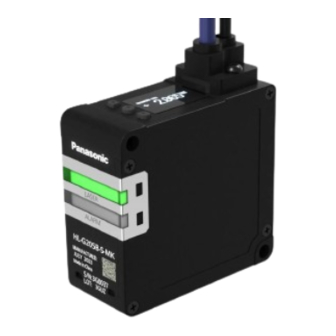
Panasonic HL-G2 Series User Manual
Laser displacement sensor, communication type
Hide thumbs
Also See for HL-G2 Series:
- User manual (160 pages) ,
- Specifications (17 pages) ,
- Installation instructions (2 pages)

Related Manuals for Panasonic HL-G2 Series


Summary of Contents for Panasonic HL-G2 Series
- Page 1 Laser Displacement Sensor HL-G2 Series User’s Manual Communication Type WUME-HLG2CM-1 2024.1 panasonic.net/id/pidsx/global...
- Page 2 (MEMO) WUME-HLG2CM-1...
- Page 3 Introduction Thank you for purchasing Laser Displacement Sensor HL-G2 Series. Before using this product, read and understand this User's Manual. Use the product correctly and in the optimum manner. Keep this manual in a safe location for reference whenever necessary.
- Page 4 Manual Configuration This chapter explains safety and handling precautions, laser Chapter 1 Before Using This Product safety standards, component names, and other information that should be checked before using this product. Chapter 2 System Configuration This chapter explains the system configuration. This chapter explains installation, connection, wiring, initial Chapter 3 Installation and Setup...
-
Page 5: Table Of Contents
Table of Contents 1 Before Using This Product..............1-1 1.1 Safety Precautions (Always observe) ..........1-2 1.2 Network Security.................1-3 1.3 Handling Precautions................1-4 1.3.1 Explanation of Graphic Symbols ............1-4 1.3.2 Handling Precautions ............... 1-4 1.4 Terminology..................1-7 1.5 Regulations and Standards ..............1-8 1.6 Conditions for Compliance with CE Marking/UKCA Marking....1-9 1.7 Laser Safety Standards ..............1-10 1.7.1 IEC / EN / JIS / GB / KS .............. - Page 6 4.4.3 Hysteresis ..................4-36 4.4.4 Teaching Mode................. 4-38 4.4.5 Tolerance ..................4-40 4.5 Output Setting ..................4-42 4.5.1 Output Delay Timer Selection ............4-42 4.5.2 Output Delay Timer Setting.............. 4-47 4.6 Input Setting..................4-48 4.6.1 Laser Stop..................4-48 4.6.2 Trigger Mode..................4-49 4.7 Alarm Setting ..................4-52 4.7.1 Alarm Delay Count ................
- Page 7 5.4.3 SLMP Supported Commands ............5-51 5.4.4 "Data Register" Device Number List ..........5-59 5.4.5 "Output" Device Number List ............5-66 6 External Communication Control (RS-485) ........6-1 6.1 RS-485 Communication Setting............6-2 6.2 Connection and Setting Method ............6-3 6.3 Modbus RTU..................6-6 6.3.1 Modbus RTU Supported Functions..........
- Page 8 (MEMO) viii WUME-HLG2CM-1...
-
Page 9: Before Using This Product
1 Before Using This Product 1.1 Safety Precautions (Always observe) ..........1-2 1.2 Network Security.................1-3 1.3 Handling Precautions................1-4 1.3.1 Explanation of Graphic Symbols ............1-4 1.3.2 Handling Precautions ............... 1-4 1.4 Terminology..................1-7 1.5 Regulations and Standards ..............1-8 1.6 Conditions for Compliance with CE Marking/UKCA Marking....1-9 1.7 Laser Safety Standards ..............1-10 1.7.1 IEC / EN / JIS / GB / KS .............. -
Page 10: Safety Precautions (Always Observe)
1.1 Safety Precautions (Always observe) 1.1 Safety Precautions (Always observe) This section explains important rules that must be observed to prevent personal injury and property damage. ■ Safety precautions items are classified into “WARNING” and “CAUTION” depending on the level of hazard. Risk of death or serious injury. -
Page 11: Network Security
1.2 Network Security 1.2 Network Security There is the risk of suffering following damage when using this product connected to the network. 1. Information leakage through this product 2. Illegal operations of this product by a malicious third party 3. Obstructing or stopping this product by a malicious third party Sufficient network security measures should be taken including the following countermeasures at your own risk to prevent such damages. -
Page 12: Handling Precautions
1.3 Handling Precautions 1.3 Handling Precautions 1.3.1 Explanation of Graphic Symbols ■ In this manual, the following symbols are used to indicate safety information that must be observed. Indicates an action that is prohibited or a matter that requires caution. Indicates an action that must be taken. - Page 13 1.3 Handling Precautions • If UKCA marking is required, the Safety Extra Low Voltage (SELV) or Protective Extra Low Voltage (PELV) of the power supply unit must comply with the EMC Regulations. ● When using this product in a positive ground environment, do not mix positive and negative grounds.
- Page 14 1.3 Handling Precautions ● Do not drop or subject this product to strong shocks. Doing so may result in an accident or failure. Other Precautions ● When this product becomes unnecessary, dispose of the product properly as industrial waste in accordance with the applicable law in the country. ●...
-
Page 15: Terminology
1.4 Terminology 1.4 Terminology Term Description A display that allows the user to check the measured distance (measured value) Measurement display between the sensor and the sensing object A value (threshold) that is used to judge if a measure value falls within the HIGH set value / LOW predetermined range. -
Page 16: Regulations And Standards
1.5 Regulations and Standards 1.5 Regulations and Standards ■ Conforming directives and conforming regulations EU Law: EMC Directive 2014/30/EU British Legislation: EMC Regulations 2016/1091 ● Applicable standards • EN 60825-1 • EN 61000-6-2 • EN 61000-6-4 ● US Regulations: FDA21 CFR1040.10, and 1040.11 (Laser Notice No.56 applied) ■... -
Page 17: Conditions For Compliance With Ce Marking/Ukca Marking
1.6 Conditions for Compliance with CE Marking/UKCA Marking 1.6 Conditions for Compliance with CE Marking/UKCA Marking To use this product as a CE marking/UKCA marking compliant product, the following conditions must be met. ● The signal and power lines connected to the product must not exceed the maximum length of the optional cable available. -
Page 18: Laser Safety Standards
1.7 Laser Safety Standards 1.7 Laser Safety Standards 1.7.1 IEC / EN / JIS / GB / KS To prevent laser products from affecting their users, IEC, EN, JIS, GB, and KS standards have the following respective standards: These standards classify laser products into classes according to the hazard level of laser, and prescribe safety and preventive measures that should be implemented for each class. -
Page 19: Fda
1.7 Laser Safety Standards 1.7.2 FDA ■ Exporting to the USA If this product is incorporated into facilities or equipment to be exported to the US, it is subject to the laser regulations of the US Food and Drug Administration (FDA). To prevent laser products from affecting their users, PART1040 (Performance Standards for Light-Emitting Products) was established as one of the FDA regulations. -
Page 20: Contents Of Package
1.8 Contents of Package 1.8 Contents of Package The following accessories are included in the product package. Before using this product, make sure that no items are missing. Products HL-G203B-S-MK/ 30 mm type HL-G205B-S-MK/ 50 mm type HL-G208B-S-MK/ 85 mm type HL-G212B-S-MK/ 120 mm type HL-G225B-S-MK/ 250 mm type ●... -
Page 21: System Configuration
2 System Configuration 2.1 System Configuration Diagram ............2-2 2.2 Description of Parts................2-4 WUME-HLG2CM-1... -
Page 22: System Configuration Diagram
2.1 System Configuration Diagram 2.1 System Configuration Diagram The figure below shows a system configuration and cables connecting each device. Ethernet communication RS-485 communication WUME-HLG2CM-1... - Page 23 2.1 System Configuration Diagram RS-485 wiring allows connection of up to 16 devices. ● This product contains built-in termination resistance. Be sure to turn ON the termination resistance on the terminal unit sensor. ● For stability of RS-485 communication, check the system operation by connecting actual devices on your own.
-
Page 24: Description Of Parts
2.2 Description of Parts 2.2 Description of Parts ■ Sensor unit Name Function Lit in green while laser beams are being emitted. Laser radiation indicator It blinks if an error occurs. Lit in orange when an measurement alarm occurs. Alarm indicator It blinks if an error occurs. - Page 25 2.2 Description of Parts ■ Operation/display section Name Function Display section (Note 1) Displays measured values, settings, and error codes Cable connector part Used when connecting the sensor with a optional cable. UP (DOWN) key ENTER key Used to change setting items and settings when configuring settings. DOWN (UP) key (Note 1) For error messages and actions to be taken, refer to...
- Page 26 2.2 Description of Parts ■ Measurement display Name Function Measurement value display The current measured value (mm) is displayed with a sign. LASER icon Displayed when the laser is turned on. Displayed depending on the state of the measured value judgment result. When the measured value exceeds the HIGH set value, "HI"...
- Page 27 2.2 Description of Parts ● The display range of measured values for each distance type is as follows. Measurement Measurement center Model name (Note 2) Display range distance (Note 1) range HL-G203B-S-MK 30 mm ±5 mm -9.5000 to +9.5000 HL-G205B-S-MK 50 mm ±10 mm -95.000 to +95.000...
- Page 28 2.2 Description of Parts ■ Setting screen (Setting mode) Name Function Shows the setting item by number. Hold down the <ENTER> key for 2 seconds on the measurement display. The screen that appears after entering the Setting mode is the first level. Menu number Following this, pressing the <ENTER>...
- Page 29 2.2 Description of Parts Hierarchica l level Menu display bar Setting item Reference page number (Number of bars) Span "4.3.6 Span" Offset "4.3.7 Offset" HIGH Set Value "4.4.1 HIGH Set Value" LOW Set Value "4.4.2 LOW Set Value" Hysteresis "4.4.3 Hysteresis" Teaching Mode "4.4.4 Teaching Mode"...
- Page 30 (MEMO) 2-10 WUME-HLG2CM-1...
-
Page 31: Installation And Setup
3 Installation and Setup 3.1 Flow of Operations up to Measurement Startup .........3-2 3.2 Sensor Installation ................3-3 3.3 Sensor Installation Direction and Angle ..........3-4 3.4 Optional Cable Connection Method ............3-7 3.5 Functions and Wiring of I/O Lines............3-9 3.5.1 Grounding ..................3-12 3.5.2 Precautions for positive ground environment........ -
Page 32: Flow Of Operations Up To Measurement Startup
3.1 Flow of Operations up to Measurement Startup 3.1 Flow of Operations up to Measurement Startup This section explains the flow of operations up to measurement startup by using workpiece detection mode as an example. Before power ON Check package contents and confirm that all parts are complete. Prepare either CN-8E-C□... -
Page 33: Sensor Installation
3.2 Sensor Installation 3.2 Sensor Installation When installing this product, use M4 captive washer screws (to be prepared separately). (Tightening torque: 0.8 N∙m or less) ● Carefully handle the sensor so that no force is applied around the connector of the optional cable. -
Page 34: Sensor Installation Direction And Angle
3.3 Sensor Installation Direction and Angle 3.3 Sensor Installation Direction and Angle To stabilize measurement (including the reduction of measurement errors), install the sensor considering the installation direction depending on the operating environment. Install the sensor so that the beam emitting part and beam receiving part surfaces are set in parallel with the measurement object. - Page 35 3.3 Sensor Installation Direction and Angle ● When the measurement object rotates To measure rotating objects, installing the sensor as shown in the figure below minimizes the effects of vertical vibration, misalignment, etc. ● When there are level differences on the surface of the measurement object To measure moving objects with level differences on the surface, installing the sensor as shown in the figure below minimizes the effect of the level edges.
- Page 36 3.3 Sensor Installation Direction and Angle ■ Installation Angle Install the sensor so that the beam emitting part and beam receiving part surfaces are set at 90 degrees (parallel) with the measurement object. <Reference> Model No. Measurement center distance Measurement range HL-G203B-S-MK 30 mm ±5 mm...
-
Page 37: Optional Cable Connection Method
3.4 Optional Cable Connection Method 3.4 Optional Cable Connection Method ● When using the optional cable, confirm that there is no foreign matters in the connector part before using the cable. ● Always grasp the connector body when connecting or disconnecting the connector. Wires may break if excessive stress is applied to the cable. - Page 38 3.4 Optional Cable Connection Method WUME-HLG2CM-1...
-
Page 39: Functions And Wiring Of I/O Lines
3.5 Functions and Wiring of I/O Lines 3.5 Functions and Wiring of I/O Lines Two types of optional cables are available. Select CN-8E-C□ for Ethernet communication. Select CN-8R-C□ for RS-485 communication. ● Before wiring, always turn the power OFF. ● Be sure to use the specified optional cables. ●... - Page 40 3.5 Functions and Wiring of I/O Lines ■ I/O circuit diagram When PNP is set (Note 1) This product operates as a normal PNP input sensor according to the PNP input specifications. However, due to the effect of the NPN/PNP switching circuit, 3.3 V is applied from the input to the outside when PNP is set.
- Page 41 3.5 Functions and Wiring of I/O Lines ■ Ethernet Circuit Diagram (Note 1) The F.G. terminal and Ethernet shield of this product and the RJ45 connector shell are internally connected. If there is a potential difference between the F.G. of this product and the F.G. of the Ethernet- connected device, an overcurrent may flow between the F.G.
-
Page 42: Grounding
3.5 Functions and Wiring of I/O Lines 3.5.1 Grounding ● The power supply (+V, 0 V) and F.G. terminals of this product are isolated by capacitors. ● The F.G. terminal and metal housing of this product are internally connected. To prevent electric shock and malfunction due to noise, use dedicated grounding with a resistance of 100 Ω... -
Page 43: Initial Startup Settings
3.6 Initial Startup Settings 3.6 Initial Startup Settings ■ Overview After turning on the power supply for the first time or executing "Set value initialization", perform the language and NPN/PNP settings. When the power supply is turned on, the startup screen is displayed for two seconds and then the language setting screen is displayed. - Page 44 (MEMO) 3-14 WUME-HLG2CM-1...
- Page 45 4 Description of Functions 4.1 List of Functions..................4-3 4.2 Bank Switching ...................4-7 4.3 Sensing Setting...................4-10 4.3.1 Sampling Frequency ................ 4-10 4.3.2 Average Times ................. 4-12 4.3.3 Brightness Tuning ................4-14 4.3.4 Hold Mode..................4-18 4.3.5 Inversion of Measured Value............4-22 4.3.6 Span....................
- Page 46 4 Description of Functions 4.11 Measured Value Resetting ..............4-80 4.12 Key Lock ...................4-81 4.12.1 Key Lock Setting ................4-81 4.12.2 Key Lock OFF ................4-82 4.13 Self-monitoring..................4-83 WUME-HLG2CM-1...
-
Page 47: Description Of Functions
4.1 List of Functions 4.1 List of Functions The items that can be set on the measurement display are as follows. ■ Received light intensity monitor Setting item Display Description of Functions Reference section page Measurement display Received light intensity The peak intensity of received light monitor (range: 0 to 1023) of the received light... - Page 48 4.1 List of Functions ■ Zero setting ON / Zero setting OFF Setting item Display Description of Functions Reference section page Measurement display Zero setting ON This function is used to forcibly set the "4.10 Zero measured value to "0". You can use Setting"...
- Page 49 4.1 List of Functions ■ Setting mode Setting item Display Description of Functions Reference section page Measurement display Bank switching Used to switch over the bank to be "4.2 Bank used. Switching" Sensing setting This is a function setting that is used to "4.3 Sensing control the received light intensity of Setting"...
- Page 50 4.1 List of Functions Setting item Display Description of Functions Reference section page RS-485 communication This is a function setting related to "6.2 Connection setting RS-485 communication. and Setting Method" System setting This includes system settings such as "4.8 System language setting and initialization.
-
Page 51: Bank Switching
4.2 Bank Switching 4.2 Bank Switching ■ Overview This product has four banks, Bank 1 to Bank 4, in order to hold some setting values. By switching the bank to use, you can easily apply the settings when needed depending on the measurement object. - Page 52 4.2 Bank Switching Setting item Set value Default value Bank Bank 1 Bank 1 Bank 2 Bank 3 Bank 4 ■ Types of setting items read from banks Major setting item Setting item Sensing setting Sampling frequency Average times Brightness tuning Hold mode Span Offset...
- Page 53 4.2 Bank Switching ■ Bank copy You can copy the settings saved in a bank to another bank using communication commands for the external host device. The copied settings will be retained even when the power is turned OFF. When using communication commands, the following combinations of copy source and copy destination banks are available.
-
Page 54: Sensing Setting
4.3 Sensing Setting 4.3 Sensing Setting ■ Overview This is a function setting that is used to control the received light intensity of this product and perform calculations on the output measurement values to ensure accurate and stable measurement. 4.3.1 Sampling Frequency ■... - Page 55 4.3 Sensing Setting Setting item Set value Default value 100 μs 200 μs Sampling Frequency 500 μs 1 ms 1 ms 2 ms WUME-HLG2CM-1 4-11...
-
Page 56: Average Times
4.3 Sensing Setting 4.3.2 Average Times ■ Overview Set the number of moving averages used to calculate measured values. This setting is used to stabilize fluctuating measured values. When the average count is set to 4 (Sampling cycle: 1 ms) ■... - Page 57 4.3 Sensing Setting ● Setting the average count to a small value enables the sensor to respond to momentary changes. Setting the average count to a large value enables the sensor to suppress the effect of momentary changes. ● When the average count is changed, the measured value is set to an indeterminate state until values are accumulated to reach the average count again.
-
Page 58: Brightness Tuning
4.3 Sensing Setting 4.3.3 Brightness Tuning ■ Overview Depending on the workpiece to be measured, you can change the beam brightness adjustment method. When measuring two workpieces with large brightness difference, use the brightness tuning which may stabilize the measurement accuracy. To select the brightness tuning, sensing objects with different brightness are required. - Page 59 4.3 Sensing Setting Setting item Set value Default value Brightness Tuning ■ Brightness Tuning Procedure When selecting Brightness tuning, both the bright portion and dark portion of the sensing object need to be registered in this product in advance. Follow the procedure below to configure the settings. Prepare two workpieces with different brightness and turn ON Brightness Tuning.
- Page 60 4.3 Sensing Setting When the Brightness Tuning has failed, "Failed" is displayed on the display section. Perform brightness adjustment using two workpieces again. ● In the following case, teaching cannot be started. • Hold mode is set to other than "None (Normal mode)". ●...
- Page 61 4.3 Sensing Setting Brightness tuning using external communication This section describes how to execute brightness tuning using communication commands from an external host device. ● During the execution of brightness tuning using communication commands, do not write data to other setting information. ●...
-
Page 62: Hold Mode
4.3 Sensing Setting 4.3.4 Hold Mode ■ Overview Set a method to hold the measured value according to the measuring method of sensing objects. ■ Setting method ● There is a dependency between hold mode and trigger mode. When "None (Normal mode)" is selected in Hold mode, Trigger mode can be set to "Hold"... - Page 63 4.3 Sensing Setting Setting item Set value Default value Peak to Peak Hold ■ Timing chart The diagram shown in the following explanation shows an example where"Hold"is set in the trigger mode. None (Normal mode) When the trigger input turns ON, the measured value is held. When the trigger input turns OFF, the hold state is released, and the value is updated and output as necessary.
- Page 64 4.3 Sensing Setting Bottom Hold Used to update and output the minimum value of the measured values as needed. During the period from when the trigger input turns ON to when it turns OFF, the minimum value data is held. Peak to Peak Hold Used to update and output the value obtained by subtracting the minimum value from the maximum value as needed.
- Page 65 4.3 Sensing Setting ● In the following cases, the held value is initialized. • When the trigger input is turned OFF • When Measured value resetting is executed • When a setting change is made to cause the measured value to be in an indeterminate state •...
-
Page 66: Inversion Of Measured Value
4.3 Sensing Setting 4.3.5 Inversion of Measured Value ■ Overview This is a function that reverses the positive / negative direction of the measured value. When set to "Reverse", only the positive/negative sign of the measured value is reversed. ■ Setting method 4-22 WUME-HLG2CM-1... - Page 67 4.3 Sensing Setting ● When set to "Normal", the measured value increases as the workpiece comes closer to this product. ● When set to "Reverse", the measured value decreases as the workpiece comes closer to this product. ● For the HIGH and LOW measurement values and the zero set correction value, changing the Inversion of Measured Value setting does not change the positive/negative sign.
-
Page 68: Span
4.3 Sensing Setting 4.3.6 Span ■ Overview This is a function that multiplies a span (factor) to the measured value after zero setting and outputs the result. By adding an optionally set value as the offset, the value is output as the final measured value. Final measured value = Span (factor) ×... - Page 69 4.3 Sensing Setting ● The set value can be set in increments of 0.0001. ● Simultaneously pressing the <UP> and <DOWN> keys while moving between the digits returns to the first digit. ● Hold down the <ENTER> key for 2 seconds on the setting screen, and the setting change is suspended and the screen returns to the previous display.
-
Page 70: Offset
4.3 Sensing Setting 4.3.7 Offset ■ Overview This function is used to add or subtract an optional value to/from the measured value. By multiplying a span (factor) to the measured value after zero setting and by adding an optionally set value as the offset, the value is output as the final measured value. Final measured value = Span (factor) ×... - Page 71 4.3 Sensing Setting ● The setting range varies depending on the distance type of this product. ● Simultaneously pressing the <UP> and <DOWN> keys while moving between the digits returns to the first digit (sign). ● Hold down the <ENTER> key for 2 seconds on the setting screen, and the setting change is suspended and the screen returns to the previous display.
-
Page 72: Judgment Setting
4.4 Judgment Setting 4.4 Judgment Setting ■ Overview This is a function setting related to judgment results of the measured value. 4.4.1 HIGH Set Value ■ Overview This function allows you to optionally set the upper limit value (HIGH set value) used to judge the measured value. - Page 73 4.4 Judgment Setting ● You can set HIGH and LOW set values by teaching. For details, refer to "4.4.4 Teaching Mode". ● Hold down the <ENTER> key for 2 seconds on the setting screen, and the setting change is suspended and the screen returns to the previous display. ●...
- Page 74 4.4 Judgment Setting Setting a"HIGH set value"directly during measurement ■ Overview In addition to the method described in HIGH Set Value, you can also set a HIGH set value directly from the measurement display during measurement. Press the <UP> key in the measurement display, and HIGH set value is displayed at the top of the display and a set threshold value is displayed at the bottom.
- Page 75 4.4 Judgment Setting ● Simultaneously pressing the <UP> and <DOWN> keys while moving between the digits returns to the first digit (sign). WUME-HLG2CM-1 4-31...
-
Page 76: Low Set Value
4.4 Judgment Setting 4.4.2 LOW Set Value ■ Overview This function allows you to optionally set the lower limit value (LOW set value) used to judge the measured value. If the measured value falls below the LOW set value, the judgment is output as LOW. ■... - Page 77 4.4 Judgment Setting Setting item Distance type Set value (mm) Default value (mm) Setting resolution (μm) LOW set value 30 mm -9.5000 to -5.0000 +9.5000 50 mm -95.000 to -10.000 +95.000 85 mm -20.000 120 mm -30.000 250 mm -950.00 to -150.00 +950.00 WUME-HLG2CM-1...
- Page 78 4.4 Judgment Setting Setting a"LOW set value"directly during measurement ■ Overview In addition to the method described in LOW Set Value, you can also set a LOW set value directly from the measurement display during measurement. Press the <DOWN> key in the measurement display, and LOW set value is displayed at the top of the display and a set value is displayed at the bottom.
- Page 79 4.4 Judgment Setting ● Simultaneously pressing the <UP> and <DOWN> keys while moving between the digits returns to the first digit (sign). WUME-HLG2CM-1 4-35...
-
Page 80: Hysteresis
4.4 Judgment Setting 4.4.3 Hysteresis ■ Overview If the sensing object vibrates in the vicinity of the HIGH set value / LOW set value, the final measured value may fluctuate, resulting in unstable operation. When a sensing workpiece is located near the HIGH set value / LOW set value, increasing the value of hysteresis makes output operations stable. - Page 81 4.4 Judgment Setting ● Set this so that the difference between the HIGH and LOW set values is more than twice the hysteresis. If set to not more than twice the hysteresis, an error will occur. ● The hysteresis setting range varies depending on the distance type of this product. ●...
-
Page 82: Teaching Mode
4.4 Judgment Setting 4.4.4 Teaching Mode ■ Overview By teaching using a sensing object, you can automatically set HIGH and LOW set values. You can select the teaching method from one of the following three types. Set value Operation Reference page 1 point teaching This method is to perform 1-point teaching on the "4.9.1 1 point Teaching"... - Page 83 4.4 Judgment Setting Setting item Set value Default value Teaching Mode 1 point 1 point 2 points 3 points ● Hold down the <ENTER> key for 2 seconds on the setting screen, and the setting change is suspended and the screen returns to the previous display. WUME-HLG2CM-1 4-39...
-
Page 84: Tolerance
4.4 Judgment Setting 4.4.5 Tolerance ■ Overview When 1-point teaching is performed, the measured value of the master workpiece plus the tolerance can be set as the HIGH set value and the measured value of the master workpiece minus the tolerance can be set as the LOW set value. This is valid only when 1-point teaching is set. - Page 85 4.4 Judgment Setting ● Changing the tolerance setting does not update the HIGH and LOW set values. After changing the setting, execute 1-point teaching again. ● You cannot set this to a value that is equal to or less than the hysteresis. ●...
-
Page 86: Output Setting
4.5 Output Setting 4.5 Output Setting ■ Overview This is a function setting related to output operation. 4.5.1 Output Delay Timer Selection ■ Overview This setting is used to set the timing from ON to OFF or from OFF to ON for the measured value judgment result (HIGH / GO/ LOW). - Page 87 4.5 Output Setting ■ Setting method ● Hold down the <ENTER> key for 2 seconds on the setting screen, and the setting change is suspended and the screen returns to the previous display. Setting item Set value Default value OFF (No timer) On Delay Timer selection Off Delay...
- Page 88 4.5 Output Setting On Delay When set to "On Delay", the output will be delayed for the timer’s time from the time when the judgment result is turned ON. If the ON duration is less than the timer’s time, the delay does not appear in the measured value judgment result.
- Page 89 4.5 Output Setting Off Delay When set to "Off Delay", the output will be delayed for the timer’s time from the time when the judgment result is turned OFF. If the OFF duration is less than the timer’s time, the delay does not appear in the measured value judgment result.
- Page 90 4.5 Output Setting 4-46 WUME-HLG2CM-1...
-
Page 91: Output Delay Timer Setting
4.5 Output Setting 4.5.2 Output Delay Timer Setting ■ Overview This setting is used to set the delay time in milliseconds for the delay timer selected in "4.5.1 Output Delay Timer Selection". ■ Setting method ● The output delay timer setting is reflected only when "Off Delay", "On Delay", or "One Shot" is selected in Output delay timer selection. -
Page 92: Input Setting
4.6 Input Setting 4.6 Input Setting ■ Overview This is a function setting related to input operation. 4.6.1 Laser Stop ■ Overview This is a function that switches ON and OFF the laser emission. When the setting is OFF, laser will be emitted. When it is ON, laser emission will be stopped. ■... -
Page 93: Trigger Mode
4.6 Input Setting 4.6.2 Trigger Mode The following describes a method to hold the final measured value using a trigger input. This mode can be selected from the following two types: "Hold" or "One Shot". ■ Hold If trigger input turns ON, this function holds the final measured value while the input is ON. ■... - Page 94 4.6 Input Setting ■ Setting method ● Trigger mode can be set to "One Shot" only when "None (Normal mode)" is selected in Hold mode. ● The hold releasing conditions are as follows. • When a setting change is made to cause the measured value to be in an indeterminate state •...
- Page 95 4.6 Input Setting Trigger input by input line ■ Timing chart for trigger input ● Do not use trigger input by I/O line and trigger input by communication at the same time. ● Trigger input by "IN1 (trigger input)" on the Input line must be continued for at least 2 ms. ●...
-
Page 96: Alarm Setting
4.7 Alarm Setting 4.7 Alarm Setting ■ Overview The alarm setting provides function settings related to data processing in an unmeasurable state. Unmeasurable state refers to a state where the light receiving waveform of CMOS does not allow for correct calculation of measured values. The types of unmeasurable states are as shown below. -
Page 97: Alarm Delay Count
4.7 Alarm Setting 4.7.1 Alarm Delay Count ■ Overview You will be notified of an alarm if an unmeasurable state is detected. This function allows you to delay the notification until the set sampling count is reached. While an alarm is being delayed, the last measured value is held. -
Page 98: Alarm Digital Output
4.7 Alarm Setting 4.7.2 Alarm Digital Output ■ Overview This function allows you to set the digital output operation at alarm occurrence (measured value display, measured value reference by communication). An alarm will be output if an unmeasurable state continues for more than the sampling count set in "4.7.1 Alarm Delay Count". - Page 99 4.7 Alarm Setting ■ Setting method ● Hold down the<ENTER>key for 2 seconds on the setting screen, and the setting change is suspended and the screen returns to the previous display. Setting item Set value Default value Alarm digital output Hold Hold Alarm...
-
Page 100: System Setting
4.8 System Setting 4.8 System Setting ■ Overview This is a function setting related to the system settings such as initialization and display language. 4.8.1 Display Digit ■ Overview This function allows you to switch the number of digits after the decimal point on the display section. - Page 101 4.8 System Setting ● Any numbers after the specified number of digits displayed are rounded down. ● Teaching may fail or errors may occur in measured value judgment results or calculation results due to the digits after the decimal point that are not displayed depending on the product type or settings.
-
Page 102: Eco Mode
4.8 System Setting 4.8.2 ECO Mode ■ Overview By setting the Eco mode to ON to turn OFF the display section except when operating the product, you can extend the life of the display section. If the Eco mode is set to ON, the display section will turn OFF when no key is operated for 180 seconds. -
Page 103: Display Inversion
4.8 System Setting 4.8.3 Display Inversion ■ Overview The display on the display section can be inverted upside down. When the display is inverted, the positions of the <UP> and <DOWN> keys are swapped. ■ Setting method ● Hold down the <ENTER> key for 2 seconds on the setting screen, and the setting change is suspended and the screen returns to the previous display. -
Page 104: Language Setting
4.8 System Setting 4.8.4 Language Setting ■ Overview This function allows you to change the language to be displayed on the display section. ■ Setting method ● Hold down the<ENTER>key for 2 seconds on the setting screen, and the setting change is suspended and the screen returns to the previous display. -
Page 105: Resetting Communication Settings
4.8 System Setting 4.8.5 Resetting Communication Settings ■ Overview This function is used to reflect the Ethernet or RS-485 settings. ■ Setting method ● Hold down the<ENTER>key for 2 seconds on the setting screen, and the setting change is suspended and the screen returns to the previous display. Setting item Set value Default value... -
Page 106: Settings Initialization
4.8 System Setting 4.8.6 Settings Initialization ■ Overview This function allows you to initialize each setting. Initialization method Operation Bank1 Initializes the settings of Bank 1. Bank2 Initializes the settings of Bank 2. Bank3 Initializes the settings of Bank 3. Bank4 Initializes the settings of Bank 4. - Page 107 4.8 System Setting ● Priority is given to initialization if any key operation or external input is performed while initialization is being executed. ● Both"Ethernet communication settings"and"RS-485 communication settings"are excluded from initialization. Manually return to initial values for these settings. ●...
-
Page 108: Point/2 Points/3 Points Teaching
4.9 1 point/2 points/3 points Teaching 4.9 1 point/2 points/3 points Teaching ■ Overview This method is used to set the HIGH set value and LOW set value using one or more sensing objects. ● When performing teaching, it is necessary to set a teaching type in advance. For details on setting the teaching type, refer to "4.4.4 Teaching Mode". -
Page 109: Point Teaching
4.9 1 point/2 points/3 points Teaching 4.9.1 1 point Teaching ■ Overview This method is to perform teaching on sensing objects and set the value obtained by adding the tolerance to the teaching result as the HIGH set value and the value obtained by subtracting the tolerance from the teaching result as the LOW set value. - Page 110 4.9 1 point/2 points/3 points Teaching Press the<ENTER>key. Teaching will be executed. When teaching is completed, "Success" is displayed on the display section. Then, the newly set HIGH set value and LOW set value are displayed in sequence, and the display returns to the measurement display.
- Page 111 4.9 1 point/2 points/3 points Teaching WUME-HLG2CM-1 4-67...
- Page 112 4.9 1 point/2 points/3 points Teaching 1 point teaching using external communication This section describes how to execute 1 point teaching using communication commands from an external host device. ● Execute teaching on the measurement display. ● During the execution of teaching using communication commands, do not write data to other setting information.
-
Page 113: Points Teaching
4.9 1 point/2 points/3 points Teaching 4.9.2 2 points Teaching ■ Overview Measure two workpieces and set the higher final measured value to the HIGH set value and the lower final measured value to the LOW set value. Set Teaching type to "2 points teaching". On the measurement display, insert the 1st sensing object. - Page 114 4.9 1 point/2 points/3 points Teaching With the 2nd sensing object inserted, press the<ENTER>key. Teaching for the 2nd point is executed. When teaching is completed,"Success"is displayed on the display section. Then, the newly set HIGH set value and LOW set value are displayed in sequence, and the display returns to the measurement display.
- Page 115 4.9 1 point/2 points/3 points Teaching WUME-HLG2CM-1 4-71...
-
Page 116: Points Teaching
4.9 1 point/2 points/3 points Teaching 2 points teaching using external communication This section describes how to execute 2 points teaching using communication commands from an external host device. ● Execute teaching on the measurement display. ● During the execution of teaching using communication commands, do not write data to other setting information. - Page 117 4.9 1 point/2 points/3 points Teaching 4.9.3 3 points Teaching ■ Overview This method is to perform teaching on three sensing objects and set the HIGH set value and LOW set value for each of them based on the measured results. Among the three measured values, the highest value is the maximum value, the second highest value is the median value, and the third highest value is the minimum value.
- Page 118 4.9 1 point/2 points/3 points Teaching Confirm that a message saying"Set 2nd Target and Push ENTER SW"is displayed at the top of the display. The display changes to the 2nd point input screen. With the 2nd sensing object inserted, press the<ENTER>key. Teaching for the 2nd point is executed.
- Page 119 4.9 1 point/2 points/3 points Teaching If the sensing object is not detected stably, for example, if two or more of the three teaching points have the same measurement value,"Failed"will be displayed. Re-examine positional relationship among the sensing objects and perform teaching again. WUME-HLG2CM-1 4-75...
- Page 120 4.9 1 point/2 points/3 points Teaching 3 points teaching using external communication This section describes how to execute 3 points teaching using communication commands from an external host device. ● Execute teaching on the measurement display. ● During the execution of teaching using communication commands, do not write data to other setting information.
- Page 121 4.9 1 point/2 points/3 points Teaching ● Screen transition by operating switches on this product is not possible during the execution of teaching using communication commands. ● The communication commands for the external host device vary depending on the communication protocol to be used. For details, refer to the table below. Communication protocol Reference page Modbus TCP...
-
Page 122: Zero Setting
4.10 Zero Setting 4.10 Zero Setting ■ Overview This function is used to forcibly set the measured value to "0". You can use the function to adjust the reference point when this product has been replaced or when the workpiece has been changed. - Page 123 4.10 Zero Setting ● If you execute Inversion of Measured Value in the state where zero set setting is complete and the measured value is set to 0, the measured value changes from 0. After executing Inversion of Measured Value, make an adjustment again. ●...
-
Page 124: Measured Value Resetting
4.11 Measured Value Resetting 4.11 Measured Value Resetting ■ Overview This function is used to reset the moving average data of the measured value or the value held by the hold function. Simultaneously hold down the<UP>and<ENTER>keys on the measurement display to reset the measured value. -
Page 125: Key Lock
4.12 Key Lock 4.12 Key Lock This function is used to disable key operation to prevent the conditions set in each setting mode from being changed by mistake. While the key lock setting is activated, all key operations other than key lock release cannot be performed. -
Page 126: Key Lock Off
4.12 Key Lock 4.12.2 Key Lock OFF While the key lock setting is ON, simultaneously hold down the <UP> and <DOWN> keys for 2 seconds. "KEY LOCK OFF"is displayed on the display section for 2 seconds and the key lock is released. -
Page 127: Self-Monitoring
4.13 Self-monitoring 4.13 Self-monitoring This product self-diagnoses and outputs its state as communication data in one of the following four states. In addition, except for the normal state, detailed status information on each state is also output. State Description Normal Indicates the normal state. - Page 128 4.13 Self-monitoring State Description Conditions Remarks Cumulative operation Cumulative operating hours exceed the – hours exceeded upper limit of this product. Caution Number of writes to The number of writes to internal memory – internal memory exceeded (non-volatile memory) has exceeded the upper limit of this product.
- Page 129 4.13 Self-monitoring ● If the measured raw value is outside the following ranges, the "Outside the measurement range" bit is set to 1. Measured raw value (mm) Distance type Minimum value Maximum value 30 mm 50 mm 85 mm 120 mm 250 mm -150 Detailed information on “Caution”...
- Page 130 4.13 Self-monitoring Bit position Description 0 (Reserved) 0 (Reserved) 0 (Reserved) 0 (Reserved) 0 (Reserved) 0 (Reserved) 0 (Reserved) 0 (Reserved) 0 (Reserved) The communication commands for the external host device vary depending on the communication protocol to be used. For details, refer to the table below. Communication protocol Reference page Modbus TCP...
-
Page 131: External Communication Control (Ethernet)
5 External Communication Control (Ethernet) 5.1 Ethernet Communication Setting ............5-2 5.1.1 Connection and Setting Method............5-2 5.2 Modbus TCP ..................5-5 5.2.1 Modbus TCP Setting Method ............5-6 5.2.2 Modbus TCP Supported Functions ..........5-8 5.2.3 Modbus TCP Function Codes ............5-10 5.2.4 Modbus TCP Setting Registers............ -
Page 132: Ethernet Communication Setting
5.1 Ethernet Communication Setting 5.1 Ethernet Communication Setting ■ Overview By using communication, you can reference and set the set values of this product from an external host device. It is also possible to reference measured values and the operating state of the product. The following three communication protocols are supported. - Page 133 5.1 Ethernet Communication Setting ■ Setting method The setting items vary depending on the communication protocol to be used. For details on the setting method, refer to the table below. Communication protocol Reference page ModbusTCP "5.2.1 Modbus TCP Setting Method" EtherNet/IP "5.3.1 EtherNet/IP Setting Method"...
- Page 134 5.1 Ethernet Communication Setting ● You can check the MAC address on the screen, but not set it. ● When changing the setting of the IP address, subnet mask, or default gateway, perform a combination error check. Therefore, even if a combination turns out to be a possible combination in the end, an error may occur when an attempt is made to change an individual setting, disabling further settings.
-
Page 135: Modbus Tcp
5.2 Modbus TCP 5.2 Modbus TCP ■ Overview By using the Modbus TCP protocol, you can write settings and operation instructions, and read the setting data, measured values, and operating state of the HL-G2 from the tool software HL- G2 Configuration Tool or an external host device. ■... -
Page 136: Modbus Tcp Setting Method
5.2 Modbus TCP 5.2.1 Modbus TCP Setting Method After selecting "Ethernet communication setting" in the Setting mode of this product, some additional settings are required depending on the communication protocol to be used. For how to select "Ethernet communication setting", refer to ""5.1.1 Connection and Setting Method"". - Page 137 5.2 Modbus TCP ● The default gateway and the IP address must exist in the same network segment (subnet). WUME-HLG2CM-1...
-
Page 138: Modbus Tcp Supported Functions
5.2 Modbus TCP 5.2.2 Modbus TCP Supported Functions ● Send and receive commands to and from this product on the measurement display. The Modbus TCP protocol supports the following functions. Function code Function Description of function 0x01 Read Coil Status Reads the ON/OFF state of a specified coil. - Page 139 5.2 Modbus TCP Error code Cause Countermeasure ● This product failed to write data. WUME-HLG2CM-1...
-
Page 140: Modbus Tcp Function Codes
5.2 Modbus TCP 5.2.3 Modbus TCP Function Codes ● Send and receive commands to and from this product on the measurement display. ■ 0X01: Read Coil Status Reads the ON/OFF state of a specified coil. The coil status is indicated in 1 bit (1 = ON, 0 = OFF). - Page 141 5.2 Modbus TCP Response message (Error) Byte position Meaning Remarks Transaction identifier Returns the request message value. Transaction identifier Protocol identifier 0x00 Protocol identifier 0x00 Message length (Upper) Length from "byte position 6" onwards Message length (Lower) Unit identifier Returns the request message value. Function code 0x81 Error code...
- Page 142 5.2 Modbus TCP Byte position Meaning Remarks Unit identifier Returns the request message value. Function code 0x03 No. of bytes (No. of registers n × 2) Length from "byte position 9" onwards Register value 1 (Upper) – Register value 1 (Lower) –...
- Page 143 5.2 Modbus TCP Byte position Meaning Remarks Register value (Lower) – Response message (normal) Byte position Meaning Remarks Transaction identifier Returns the request message value. Transaction identifier Protocol identifier 0x00 Protocol identifier 0x00 Message length (Upper) Length from "byte position 6" onwards Message length (Lower) Unit identifier Returns the request message value.
- Page 144 5.2 Modbus TCP Byte position Meaning Remarks Message length (Upper) Length from "byte position 6" onwards Message length (Lower) Unit identifier – Function code 0x10 WRITE register address (Upper) – WRITE register address (Lower) – WRITE No. of registers (Upper) –...
- Page 145 5.2 Modbus TCP Byte position Meaning Remarks Unit identifier Returns the request message value. Function code 0x90 Error code – ● Always use "0” for the protocol identifier. If a value other than 0 is specified, the message is discarded. ●...
- Page 146 5.2 Modbus TCP Operation of multiple coil/register access functions in the event of an error In Modbus communication, Read Coil Status, Read Holding Register, and Write Multiple registers access multiple coils/registers at the same time. If an error occurs when accessing some or all coils/registers, these functions will operate as follows.
-
Page 147: Modbus Tcp Setting Registers
5.2 Modbus TCP 5.2.4 Modbus TCP Setting Registers ● In a Modbus protocol message, specify a value obtained by subtracting 400001 from the address listed in the table below. Size Register Data item Description Set value Attribute address (bytes) 400011 Sensor state Notifies the state of this product. - Page 148 5.2 Modbus TCP Size Register Data item Description Set value Attribute address (bytes) 400058 Bank switching Switches the bank in which the 1: Bank 1 set values are to be saved. 2: Bank 2 3: Bank 3 4: Bank 4 400059 Usage prohibited 400060...
- Page 149 5.2 Modbus TCP Size Register Data item Description Set value Attribute address (bytes) 120 mm type: Min. value: -950,000, Max. value: 950,000 250 mm type: Min. value: -9,500,000, Max. value: 9,500,000 400103 LOW set value Sets the LOW set value. 30 mm type: Min.
- Page 150 5.2 Modbus TCP Size Register Data item Description Set value Attribute address (bytes) 1: Display 3 digits after the decimal point 2: Display 2 digits after the decimal point 3: Display 1 digit after the decimal point [50 mm / 85 mm / 120 mm distance type] 1: Display 3 digits...
- Page 151 5.2 Modbus TCP Size Register Data item Description Set value Attribute address (bytes) 2: Bottom hold 3: Peak-to-peak hold 400116 Span Multiplies the measured value 1000 to 99999 after zero setting by a span (factor) and outputs the result. This value is expressed as an integer value multiplied by 10,000.
- Page 152 5.2 Modbus TCP Size Register Data item Description Set value Attribute address (bytes) 400125 Alarm digital output Sets the digital output state at 0: Hold alarm occurrence. 1: In Alarm state 400126 Brightness Tuning Sets the laser beam brightness 0: OFF adjustment method depending 1: ON on the target workpiece to be...
- Page 153 5.2 Modbus TCP Size Register Data item Description Set value Attribute address (bytes) 2: 2nd point being executed 3: Success 4: Failed 400145 Usage prohibited 400146 Brightness Tuning Used for executing brightness 0: Execute 1st point setting tuning for the 1st point. 1 to 255: (Reserved) (Note 1) 400147...
- Page 154 5.2 Modbus TCP Size Register Data item Description Set value Attribute address (bytes) 400165 Default Gateway (2nd octet) 400166 Default Gateway (1st octet) 400167 Communication Sets the communication speed. 0: 9600 bps speed 1: 19200 bps 2: 38400 bps 3: 115200 bps 4: 230400 bps 400168 Parity/Stop Bit...
-
Page 155: List Of Coils
5.2 Modbus TCP 5.2.5 List of Coils ● When using setting registers for communication commands, specify a value obtained by subtracting 1 from the coil address listed in the table below. Register Coil Data item Description Attri address address bute 400011 Alarm state 0: Not in Alarm state... - Page 156 5.2 Modbus TCP Register Coil Data item Description Attri address address bute Outside the measurement 0: No occurrence of outside the measurement range range 1: Occurrence of outside the measurement range Excessive extraneous light 0: No occurrence of excessive extraneous light 1: Occurrence of excessive extraneous light 21 to 32 Reserved;...
-
Page 157: Ethernet/Ip
5.3 EtherNet/IP 5.3 EtherNet/IP ■ Overview EtherNet/IP performs cyclic communication or message communication with external host devices that support EtherNet/IP. ■ Cyclic communication This is a function that performs data transmission at a constant interval (RPI) between this product and external host devices. In cyclic communication, one device opens a communication line called a connection to the partner device. -
Page 158: Ethernet/Ip Setting Method
5.3 EtherNet/IP 5.3.1 EtherNet/IP Setting Method After selecting "Ethernet communication setting" in the Setting mode of this product, some additional settings are required depending on the communication protocol to be used. For how to select "Ethernet communication setting", refer to ""5.1.1 Connection and Setting Method"". - Page 159 Registration of EDS (Electronic Data Sheets) files Register EDS files of this product in the external device. The EDS files can be downloaded from our website: https://industrial.panasonic.com/ac/e/dl_center/software/ For details on how to register EDS files, check the instruction manual of the external device to be used.
- Page 160 5.3 EtherNet/IP Cyclic communication setting data Item name Settable range Specifying Real time formats O→T Real time format Heartbeat format T→O Real time format Modeless format Forward Open parameters O→T RPI 10 to 10000 (milliseconds) O→T Network Connection Parameters 0x4802 (Redundant Owner: No Connection Type: Point to Point Priority: Scheduled...
-
Page 161: Ethernet/Ip Supported Functions
5.3 EtherNet/IP 5.3.2 EtherNet/IP Supported Functions ● Send and receive commands to and from this product on the measurement display. This product supports the following EtherNet/IP objects. ■ 0x01 Identity Object Class attributes Access Name Remarks Revision – Max Instance –... - Page 162 5.3 EtherNet/IP ■ 0x02 Message Router Object Class attributes Access Name Remarks Revision – Max Instance Not returned by Get_Attribute_All. Number of Instances Not returned by Get_Attribute_All. Maximum ID Number Class Attributes – Maximum ID Number Instance – Attributes (Note 1) Although this product does not support class attribute IDs 4 and 5, it returns 0 for these attributes when Get_Attribute_All is selected.
- Page 163 5.3 EtherNet/IP ■ 0xF5 TCP/IP Interface Class attributes Access Name Remarks Revision – Max Instance – Num Instance – Maximum ID Number Class Attributes – Maximum ID Number Instance – Attributes Instance attributes Name Remarks Status (Note 1) – Configuration Capability –...
- Page 164 5.3 EtherNet/IP (Note 1) ○: Supported, ×: Not supported ■ 0xF6 Ethernet Link Class attributes Access Name Remarks Revision – Max Instance – Number of Instances – Instance attributes Name Remarks Get Interface Speed – Get Interface Flags – Get Physical Address –...
- Page 165 5.3 EtherNet/IP Instance attributes (Instance ID: 100 T->O) Access Name Remarks Data For details, refer to ""5.3.3 Cyclic Communication Output Information"". Size Services Service name Instance Remarks 0x0E Get_Attribute_Single ○ ○ – (Note 1) ○: Supported, ×: Not supported ■ 0x64 HL-G2 Object Class attributes None Instance attributes (Instance ID: 1)
- Page 166 5.3 EtherNet/IP Error code Description Countermeasure 0x10 Not in executable state Review the state of this product. 0x14 Attribute not supported Review the attribute ID. 0x0E Attribute cannot be written Review the service ID or attribute ID. 0x2C Attribute cannot be read Review the service ID or attribute ID.
-
Page 167: Cyclic Communication Output Information
5.3 EtherNet/IP 5.3.3 Cyclic Communication Output Information This product uses the cyclic communication function to cyclically send measured values and the operating status of this product to external devices. The contents of the data to be sent during cyclic communication (same as the contents returned by 0x04 Assembly Object - Instance ID: 100 - Attribute ID: 3) are shown below. -
Page 168: Message Communication Commands
5.3 EtherNet/IP Byte Description Remarks position position Number of writes to internal – memory exceeded 2 to 15 (Reserved) – 10.11 Beam-emitting circuit error – (Reserved) – System error Turns ON when an E1xx error occurs. 3 to 15 (Reserved) –... -
Page 169: Hl-G2 Object Attribute List
5.3 EtherNet/IP 5.3.5 HL-G2 Object Attribute List Attribute Size Data item Description Set value Access (dec) (bytes) 2304 Sensor state Notifies the state of this product. Refer to byte positions 4 and 5 in "5.3.3 Cyclic Communication Output Information". 2305 Self-monitoring Notifies that an issue that Refer to byte... - Page 170 5.3 EtherNet/IP Attribute Size Data item Description Set value Access (dec) (bytes) 5: Copy from Bank 2 to Bank 4 6: Copy from Bank 3 to Bank 1 7: Copy from Bank 3 to Bank 2 8: Copy from Bank 3 to Bank 4 9: Copy from Bank 4 to Bank 1...
- Page 171 5.3 EtherNet/IP Attribute Size Data item Description Set value Access (dec) (bytes) 250 mm type: Min. value: -9,500,000, Max. value: 9,500,000 2320 Hysteresis Sets the hysteresis. 30 mm type: Min. Get/Set value: 0, Max. value: The minimum value and 95,000 maximum value vary depending 50 mm type: Min.
- Page 172 5.3 EtherNet/IP Attribute Size Data item Description Set value Access (dec) (bytes) 3: Display 1 digit after the decimal point 4: Do not display after the decimal point [250 mm distance type] 2: Display 2 digits after the decimal point 3: Display 1 digit after the decimal point...
- Page 173 5.3 EtherNet/IP Attribute Size Data item Description Set value Access (dec) (bytes) 120 mm type: Min. value: -950,000, Max. value: 950,000 250 mm type: Min. value: -9,500,000, Max. value: 9,500,000 2332 Tolerance Sets the tolerance. 30 mm type: Min. Get/Set value: 1, Max.
- Page 174 5.3 EtherNet/IP Attribute Size Data item Description Set value Access (dec) (bytes) 2342 Teaching execution Used for reading the teaching 0: Not executed state state. 1: Being executed 2: Success 3: Failed 2343 Teaching Mode Sets the teaching method. 1: 1 point Get/Set 2: 2 points 3: 3 points...
- Page 175 5.3 EtherNet/IP ● When the measured value is above the positive limit of the display range, "+9,600,000 (in increments of 0.1 μm)" is output. ● When the measured value is below the negative limit of the display range, "-9,600,000 (in increments of 0.1 μm)"...
-
Page 176: Slmp
5.4 SLMP 5.4 SLMP ■ Overview SLMP has the following two types of functions. ■ Client functions Clients write data of this product to an external host device cyclically. ■ Server functions This product functions as a server to receive commands from an external host device and return a response. -
Page 177: Slmp Setting Method
5.4 SLMP 5.4.1 SLMP Setting Method After selecting "Ethernet communication setting" in the Setting mode of this product, some additional settings are required depending on the communication protocol to be used. For how to select "Ethernet communication setting", refer to ""5.1.1 Connection and Setting Method"". - Page 178 5.4 SLMP ● All bits in the host address segment of the IP address cannot be set to 1's. ● All bits in the network address segment of the IP address cannot be set to 0’s. 4. Default Gateway ● The first octet cannot be set to 0, 127, or 224 to 255. (However, 0.0.0.0 can be set.) 5.
-
Page 179: Slmp Supported Functions
5.4 SLMP 5.4.2 SLMP Supported Functions ● Send and receive commands to and from this product on the measurement display. This section describes the details of various functions of the Seamless Message Protocol (SLMP) supported by this product. ■ Common specifications ●... - Page 180 5.4 SLMP Type Operation Processing Parameter setting Device information Responds to a device information comparison request. comparison ■ Client functions Type Operation Processing Internal memory Batch write This product uses this command to perform cyclic writing. The device code of the write destination is fixed to "Data register (A8H)".
-
Page 181: Slmp Supported Commands
5.4 SLMP 5.4.3 SLMP Supported Commands ● Send and receive commands to and from this product on the measurement display. ■ Server function supported command list Type Operation Command name Command code Supported PDU (Note 1) Type (Hex) EMT LMT Internal memory Batch read Read... - Page 182 5.4 SLMP -: Not covered by specifications (Note 2) No response is returned. (Note 3) The complete code C05CH is returned in the requested type. (Note 4) Type name code: 0109H Vendor code: 02000008H ● For device types that can be specified with this product, refer to "List of Supported Device Codes".
- Page 183 5.4 SLMP ● The method to start "Cyclic writing" of the client functions is as follows. [Start] • Using the tool software HL-G2 Configuration Tool, set "Automatic writing after starting" to "ON", and then restart this product. Automatic writing starts. •...
- Page 184 5.4 SLMP For details on the setting method, refer to the User's Manual for the tool softwareHL-G2 Configuration Tool. Client communication setting Setting item Description Set value Default value Request Write destination IP address for cyclic 000.000.000.000 to destination IP writing 255.255.255.255 192.168.1.100...
- Page 185 5.4 SLMP Write data Size Details / Remarks Number (byte) devices Bit 4 Judgment output state (LO) Bit 5 Judgment output state at timer OFF (HI) Bit 6 Judgment output state at timer OFF (GO) Bit 7 Judgment output state at timer OFF (LO) Bit 8 Hold state Bit 9 Zero setting state Bit 10 Laser state...
- Page 186 5.4 SLMP Write data Size Details / Remarks Number (byte) devices Bit 15 Error Detailed information of "Error" specified by the self-monitoring function Bit 0 Beam-emitting circuit error Bit 1 - Bit 2 System error Bit 3 - Bit 4 - Bit 5 - Bit 6 - Bit 7 -...
- Page 187 5.4 SLMP ■ Supported complete codes Use case when an error occurs Complete code The received SLMP request message has been properly processed. 0000H The received SLMP request message is either one of the following. ● Command is non-compliant. C059H ●...
- Page 188 5.4 SLMP Operation of multiple device access commands in the event of an error In SLMP communication, there are a bulk read command and a bulk write command that allow a consecutive access to multiple devices by specifying the start device number and the number of devices.
-
Page 189: Data Register" Device Number List
5.4 SLMP 5.4.4 "Data Register" Device Number List Size Device Data item Description Set value Attribute number (bytes) Sensor state Notifies the state of this product. The byte positions 0 to 15 in "5.4.5 "Output" Device Number List" are arranged in numbered order from the upper bits. - Page 190 5.4 SLMP Size Device Data item Description Set value Attribute number (bytes) 1 to 255: (Reserved) (Note 1) Bank switching Switches the bank in which the 1: Bank 1 set values are to be saved. 2: Bank 2 3: Bank 3 4: Bank 4 Bank copy Copies the settings saved in...
- Page 191 5.4 SLMP Size Device Data item Description Set value Attribute number (bytes) 120 mm type: Min. value: -950,000, Max. value: 950,000 250 mm type: Min. value: -9,500,000, Max. value: 9,500,000 LOW set value Sets the LOW set value. 30 mm type: Min. value: -95,000, Max.
- Page 192 5.4 SLMP Size Device Data item Description Set value Attribute number (bytes) 1: Display 3 digits after the decimal point 2: Display 2 digits after the decimal point 3: Display 1 digit after the decimal point [50 mm / 85 mm / 120 mm distance type] 1: Display 3 digits...
- Page 193 5.4 SLMP Size Device Data item Description Set value Attribute number (bytes) 2: Bottom hold 3: Peak-to-peak hold Span Multiplies the measured value 1000 to 99999 after zero setting by a span (factor) and outputs the result. This value is expressed as an integer value multiplied by 10,000.
- Page 194 5.4 SLMP Size Device Data item Description Set value Attribute number (bytes) Alarm digital output Sets the digital output state at 0: Hold alarm occurrence. 1: In Alarm state Brightness Tuning Sets the laser beam brightness 0: OFF adjustment method depending 1: ON on the target workpiece to be measured.
- Page 195 5.4 SLMP Size Device Data item Description Set value Attribute number (bytes) 1 to 255: (Reserved) (Note 1) Laser Stop Sets ON/OFF of laser emission. 0: OFF (Laser emitted) 1: ON (Emission stopped) Resetting Reflects the Ethernet or RS-485 0: Execute communication settings.
-
Page 196: Output" Device Number List
5.4 SLMP 5.4.5 "Output" Device Number List Device Data item Description Attrib number Alarm state 0: Not in Alarm state 1: In Alarm state Data in an indeterminate state 0: Not in Indeterminate state 1: Indeterminate state Judgment output state (HI) 0: OFF 1: ON Judgment output state (GO) - Page 197 5.4 SLMP Device Data item Description Attrib number Excessive extraneous light 0: No occurrence of excessive extraneous light 1: Occurrence of excessive extraneous light 20 to 31 ― Reserved; indeterminate value will be read. Cumulative operation hours exceeded 0: No occurrence of cumulative operation hours exceeded 1: Occurrence of cumulative operation hours exceeded...
- Page 198 (MEMO) 5-68 WUME-HLG2CM-1...
- Page 199 6 External Communication Control (RS-485) 6.1 RS-485 Communication Setting............6-2 6.2 Connection and Setting Method ............6-3 6.3 Modbus RTU..................6-6 6.3.1 Modbus RTU Supported Functions..........6-8 6.3.2 Modbus RTU Function Codes............6-10 6.3.3 Modbus RTU Setting Registers............6-16 6.3.4 List of Coils ..................6-24 WUME-HLG2CM-1...
-
Page 200: Communication Setting
6.1 RS-485 Communication Setting 6.1 RS-485 Communication Setting ■ Overview By using communication, you can reference and set the set values of this product from an external host device. It is also possible to reference measured values and the operating state of the product. The following communication protocol is supported. -
Page 201: Connection And Setting Method
6.2 Connection and Setting Method 6.2 Connection and Setting Method ■ Communication specifications Item Settings Communication method Half-duplex Communication speed (bps) 9,600 bps, 19,200 bps, 38,400 bps, 115,200 bps, 230,400 bps Synchronization method Start-stop synchronization Data length 8 bits No parity + Stop bit length: 2 bits, Parity/Stop Bit Even parity + Stop bit length: 1 bit, Odd parity + Stop bit length: 1 bit... - Page 202 6.2 Connection and Setting Method ■ Setting method Setting item Description Set value Default value Sets the HL-G2 that Termination resistance constitutes a final terminal. Assigns a unique address 001 to 247 number to identify the Device Address device via the Modbus RTU protocol.
- Page 203 6.2 Connection and Setting Method ● Simultaneously pressing the <UP> and <DOWN> keys while moving between the device address digits returns to the first digit. WUME-HLG2CM-1...
-
Page 204: Modbus Rtu
6.3 Modbus RTU 6.3 Modbus RTU ■ Overview By using the Modbus RTU protocol, you can write settings and operation instructions, and read the setting data, measured values, and operating state of this product from the tool software HL-G2 Configuration Tool or an external host device. ■... - Page 205 6.3 Modbus RTU ● The Modbus standard treats all registers as 2 bytes for message processing, which means that 1-byte registers in this product are expanded to 2 bytes, and 4-byte registers are divided into two 2-byte registers. ● Data is stored in the 2-byte and 4-byte registers in the following positional relationships. ●...
-
Page 206: Modbus Rtu Supported Functions
6.3 Modbus RTU 6.3.1 Modbus RTU Supported Functions ● Send and receive commands to and from this product on the measurement display. The Modbus RTU protocol supports the following functions. Function code Function Description of function 0x01 Read Coil Status Reads the ON/OFF state of a specified coil. - Page 207 6.3 Modbus RTU Error code Description Countermeasure ● This product failed to write data. WUME-HLG2CM-1...
-
Page 208: Modbus Rtu Function Codes
6.3 Modbus RTU 6.3.2 Modbus RTU Function Codes ● Send and receive commands to and from this product on the measurement display. ■ 0X01: Read Coil Status Reads the ON/OFF state of a specified coil. The coil status is indicated in 1 bit (1 = ON, 0 = OFF). - Page 209 6.3 Modbus RTU ■ 0x03: Read Holding Register Reads the value of specified holding register. Since the register data is 16 bits, it is stored in 2 bytes in the response message. The maximum number of holding registers that can be read in a single session is 125. Request message Byte position Meaning...
- Page 210 6.3 Modbus RTU ■ 0x06: Preset Single Register Changes the content of a specified holding register. The maximum number of holding registers that can be written in a single session is 1. When changing multiple holding registers, use function code 0x10. Request message Byte position Meaning...
- Page 211 6.3 Modbus RTU Request message Byte position Meaning Remarks Unit identifier – Function code 0x10 WRITE register address (Upper) – WRITE register address (Lower) – WRITE No. of registers (Upper) – WRITE No. of registers (Lower) – No. of bytes (No. of registers n × 2) Length from "byte position 7"...
- Page 212 6.3 Modbus RTU ● For the registers and coils that can be specified, refer to "6.3.3 Modbus RTU Setting Registers" "6.3.4 List of Coils". ■ CRC calculation method The CRC used for Modbus RTU is calculated using the CRC-16 algorithm (with 0xA001 as the generator polynomial).
- Page 213 6.3 Modbus RTU Operation of multiple coil/register access functions in the event of an error In Modbus communication, Read Coil Status, Read Holding Register, and Write Multiple registers access multiple coils/registers at the same time. If an error occurs when accessing some or all coils/registers, these functions will operate as follows.
-
Page 214: Modbus Rtu Setting Registers
6.3 Modbus RTU 6.3.3 Modbus RTU Setting Registers ● In a Modbus protocol message, specify a value obtained by subtracting 400001 from the address listed in the table below. Size Register Data item Description Set value Attribute address (bytes) 400011 Sensor state Notifies the state of this product. - Page 215 6.3 Modbus RTU Size Register Data item Description Set value Attribute address (bytes) 400058 Bank switching Switches the bank in which the 1: Bank 1 set values are to be saved. 2: Bank 2 3: Bank 3 4: Bank 4 400059 Usage prohibited 400060...
- Page 216 6.3 Modbus RTU Size Register Data item Description Set value Attribute address (bytes) 120 mm type: Min. value: -950,000, Max. value: 950,000 250 mm type: Min. value: -9,500,000, Max. value: 9,500,000 400103 LOW set value Sets the LOW set value. 30 mm type: Min.
- Page 217 6.3 Modbus RTU Size Register Data item Description Set value Attribute address (bytes) 1: Display 3 digits after the decimal point 2: Display 2 digits after the decimal point 3: Display 1 digit after the decimal point [50 mm / 85 mm / 120 mm distance type] 1: Display 3 digits...
- Page 218 6.3 Modbus RTU Size Register Data item Description Set value Attribute address (bytes) 2: Bottom hold 3: Peak-to-peak hold 400116 Span Multiplies the measured value 1000 to 99999 after zero setting by a span (factor) and outputs the result. This value is expressed as an integer value multiplied by 10,000.
- Page 219 6.3 Modbus RTU Size Register Data item Description Set value Attribute address (bytes) 400125 Alarm digital output Sets the digital output state at 0: Hold alarm occurrence. 1: In Alarm state 400126 Brightness Tuning Sets the laser beam brightness 0: OFF adjustment method depending 1: ON on the target workpiece to be...
- Page 220 6.3 Modbus RTU Size Register Data item Description Set value Attribute address (bytes) 2: 2nd point being executed 3: Success 4: Failed 400145 Usage prohibited 400146 Brightness Tuning Used for executing brightness 0: Execute 1st point setting tuning for the 1st point. 1 to 255: (Reserved) (Note 1) 400147...
- Page 221 6.3 Modbus RTU Size Register Data item Description Set value Attribute address (bytes) 400165 Default Gateway (2nd octet) 400166 Default Gateway (1st octet) 400167 Communication Sets the communication speed. 0: 9600 bps speed 1: 19200 bps 2: 38400 bps 3: 115200 bps 4: 230400 bps 400168 Parity/Stop Bit...
-
Page 222: List Of Coils
6.3 Modbus RTU 6.3.4 List of Coils ● When using setting registers for communication commands, specify a value obtained by subtracting 1 from the coil address listed in the table below. Register Coil Data item Description Attri address address bute 400011 Alarm state 0: Not in Alarm state... - Page 223 6.3 Modbus RTU Register Coil Data item Description Attri address address bute Outside the measurement 0: No occurrence of outside the measurement range range 1: Occurrence of outside the measurement range Excessive extraneous light 0: No occurrence of excessive extraneous light 1: Occurrence of excessive extraneous light 21 to 32 Reserved;...
- Page 224 (MEMO) 6-26 WUME-HLG2CM-1...
-
Page 225: Maintenance
7 Maintenance 7.1 Maintenance and Inspection ...............7-2 7.1.1 Maintenance Precautions ..............7-2 7.1.2 Main Inspection Items ..............7-2 WUME-HLG2CM-1... -
Page 226: Maintenance And Inspection
7.1 Maintenance and Inspection 7.1 Maintenance and Inspection 7.1.1 Maintenance Precautions ● When cleaning, be sure to turn off the power supply to do cleaning while the laser radiation is stopped. ● Never use thinner, benzene, or other organic solvents to wipe off dirt or dust because some parts are resin-molded. -
Page 227: Troubleshooting
8 Troubleshooting 8.1 Solutions to Problems .................8-2 8.2 Error Messages and Action Methods..........8-5 WUME-HLG2CM-1... -
Page 228: Solutions To Problems
8.1 Solutions to Problems 8.1 Solutions to Problems Solutions to frequently encountered problems and errors are described below. ● Check the wiring. ● Check if the NPN/PNP setting is correct. ● Check the voltage and capacity of the power supply. Reference Symptom Cause... - Page 229 8.1 Solutions to Problems Reference Symptom Cause Action method page "4.3.1 Sam The intensity of received light pling is judged to be insufficient Frequency" Alarm indicator is Increase the sampling cycle. because it exceeds the lit and "4.7 Alarm adjustment range. measurement Setting"...
- Page 230 8.1 Solutions to Problems Reference Symptom Cause Action method page using external communica tion" "2 points teaching using external communica tion" "3 points teaching using external communica tion" ● If the product still does not operate normally after you check the above, contact our office. WUME-HLG2CM-1...
-
Page 231: Error Messages And Action Methods
8.2 Error Messages and Action Methods 8.2 Error Messages and Action Methods If an error occurs during setting or measurement, one of the error codes listed below will be displayed on the display section. Error code Description Action method Dark level adjustment error Install the sensor so that strong light or E100** fluctuating light does not enter the sensor, and... - Page 232 (MEMO) WUME-HLG2CM-1...
-
Page 233: Specifications And Dimensions
9 Specifications and Dimensions 9.1 Specifications..................9-2 9.1.1 Beam Diameter ................9-4 9.1.2 Mutual Interference Area ..............9-5 9.2 Shapes and Dimensions ..............9-9 9.2.1 Product..................... 9-9 9.2.2 Optional Cable ................. 9-10 9.2.3 Optional Cable Installation Diagram ..........9-12 WUME-HLG2CM-1... -
Page 234: Specifications
9.1 Specifications 9.1 Specifications Model name HL-G203B-S- HL-G205B-S- HL-G208B-S- HL-G212B-S- HL-G225B-S- Measurement 30 mm 50 mm 85 mm 120 mm 250 mm center distance Measurement range ±5 mm ±10 mm ±20 mm ±30 mm ±150 mm X axis: approx. X axis: approx. X axis: approx. - Page 235 9.1 Specifications Model name HL-G203B-S- HL-G205B-S- HL-G208B-S- HL-G212B-S- HL-G225B-S- ● Input conditions Invalid: 0 to 11 VDC or when released Valid: 19 to 26.4 VDC Laser radiation Lit while laser beams are being emitted (Green LED) Alarm Lit when measurement is not possible due to insufficient or excessive received light intensity, or due to excessive extraneous light (Orange LED) Display section 0.9 inch organic EL...
-
Page 236: Beam Diameter
9.1 Specifications (Note 3) The beam diameter is defined as 1/e (approx. 13.5 %) of the center light intensity. Due to leak light outside the defined range, the measurement values may be affected if the reflectance around the detecting point is higher than that of the detecting point. (Note 4) This product complies with the FDA regulations (FDA 21 CFR 1040.10 and 1040.11) in accordance with FDA Laser Notice No. -
Page 237: Mutual Interference Area
9.1 Specifications 9.1.2 Mutual Interference Area When two or more units of this product are installed side by side, no mutual interference will occur as long as the laser spots of the other units are outside the shaded area shown in the figure below. - Page 238 9.1 Specifications ■ 85 mm type (HL-G208B-S-MK) Unit: mm WUME-HLG2CM-1...
- Page 239 9.1 Specifications ■ 120 mm type (HL-G212B-S-MK) Unit: mm WUME-HLG2CM-1...
- Page 240 9.1 Specifications ■ 250 mm type (HL-G225B-S-MK) Unit: mm WUME-HLG2CM-1...
-
Page 241: Shapes And Dimensions
9.2 Shapes and Dimensions 9.2 Shapes and Dimensions 9.2.1 Product HL-G2□□B-S-MK Unit: mm WUME-HLG2CM-1... -
Page 242: Optional Cable
9.2 Shapes and Dimensions 9.2.2 Optional Cable CN-8E-C□ (Ethernet type) Unit: mm 9-10 WUME-HLG2CM-1... - Page 243 9.2 Shapes and Dimensions CN-8R-C□ (RS-485 type) Unit: mm WUME-HLG2CM-1 9-11...
-
Page 244: Optional Cable Installation Diagram
9.2 Shapes and Dimensions 9.2.3 Optional Cable Installation Diagram Unit: mm 9-12 WUME-HLG2CM-1... -
Page 245: Appendix Screen Transition List
Appendix Screen Transition List Screen Transition List ................App-2 WUME-HLG2CM-1 App-1... -
Page 246: Screen Transition List
Screen Transition List Screen Transition List App-2 WUME-HLG2CM-1... - Page 247 Screen Transition List WUME-HLG2CM-1 App-3...
- Page 248 (MEMO) App-4 WUME-HLG2CM-1...
- Page 249 Revision History Revision Revision date Revision item history First edition January 2024 WUME-HLG2CM-1...
- Page 250 (MEMO) WUME-HLG2CM-1...
- Page 251 (MEMO) WUME-HLG2CM-1...
- Page 252 Panasonic Industry Co., Ltd. Panasonic Industrial Devices SUNX Co., Ltd. https://panasonic.net/id/pidsx/global Please visit our website for inquiries and about our sales network. Panasonic Industrial Devices SUNX Co., Ltd. 2024 January 2024 WUME-HLG2CM-1...
Need help?
Do you have a question about the HL-G2 Series and is the answer not in the manual?
Questions and answers