Table of Contents
Advertisement
Quick Links
Advertisement
Table of Contents

Related Manuals for Tiso CENTURION-M AUIA.097-10 Series


Summary of Contents for Tiso CENTURION-M AUIA.097-10 Series
- Page 1 "TiSO-PRODUCTION" LTD SERVO-DRIVEN TRIPOD TURNSTILES series of CENTURION-M AUIA.097-10, BASTION-M AUIA.095-10, SKULL-M AUIA.096-10, TWIX-M AUIA.137-10 CENTURION-M BASTION-M SKULL-M TWIX-M OPERATION AND INSTALLATION MANUAL Combined, rev.1.3.2 2024 UKRAINE...
-
Page 2: Table Of Contents
Operation Manual CONTENTS INTRODUCTION ................................3 CUSTOMER WARNINGS ON SAFE OPERATION OF THE TURNSTILE ..............4 1. DESCRIPTION AND OPERATION ...........................5 1.1 General Information and Purpose..........................5 1.2 Specifications................................6 1.3 Product components and scope of delivery ........................6 1.4 Design and operation ..............................8 1.5 Instrumentation, tools and accessories ........................ -
Page 3: Introduction
Operation Manual INTRODUCTION This Operation Manual (hereinafter referred to as OM) covers the servo-operated turnstile (hereinafter referred to as the "turnstile"). The Operation Manual contains information about design, specifications, installation for proper operation and maintenance of the turnstile. This Operation Manual is prepared in compliance with the specification requirements... -
Page 4: Customer Warnings On Safe Operation Of The Turnstile
Operation Manual CUSTOMER WARNINGS ON SAFE OPERATION OF THE TURNSTILE These warnings are designed to ensure safety during operation of the turnstile to prevent violation of safety features by improper installation or operation. These warnings are aimed at drawing attention of the customer to safety problems. -
Page 5: Description And Operation
Operation Manual 1. DESCRIPTION AND OPERATION 1.1 General Information and Purpose. 1.1.1 Turnstile purpose: The turnstile is designed for pedestrian movement control at access points of industrial enterprises, banks, stadiums, administrative facilities etc. due to command signals of access control system (from keypad, proximity card readers) or manually (from manual control panel). -
Page 6: Specifications
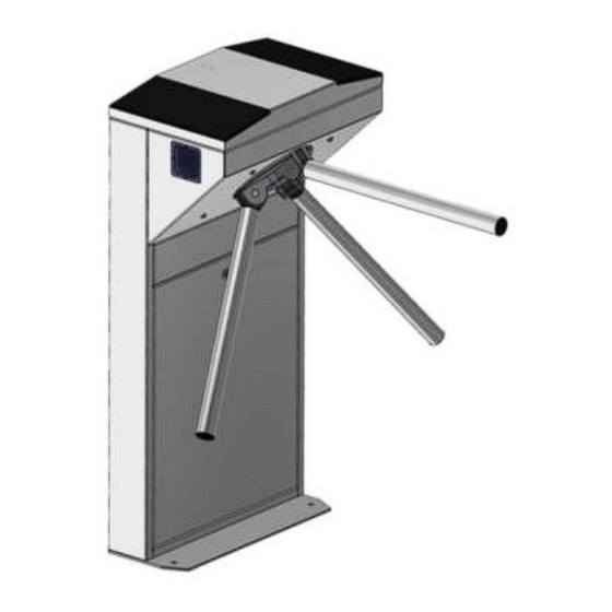
Operation Manual 1.2 Specifications Table 4 - Specifications Parameter name Parameter value Minimum traffic flow capacity in single access mode 25 person/min. Maximum access way width 600 mm Power supply voltage: 100 240 V~ 50/60 Hz - AC mains (primary) - DC power supply (secondary) 12 V Consumed power, no more than... - Page 7 Operation Manual 1.3.2 Turnstile scope of delivery (standard): Tripod turnstile; Hub with barrier rods; Control panel; Anchors (4 pcs.); Data sheet; For convenience of delivery the turnstile is supplied ready-to-install with dismounted barrier rods (See Fig.2). 1.3.3 The turnstile design, overall and installation dimensions (see Fig.3) Fig.2.
-
Page 8: Design And Operation
Operation Manual 1.4 Design and operation 1.4.1 Turnstile design 1.4.1.1 The turnstile body is a metalware, which footing 10 (See Fig.1) is installed on an even surface by means of Redibolt anchors. The turnstile status is displayed by LED display boards 2, built in the turnstile body. - Page 9 Operation Manual 1.4.3 Turnstile principle of operation 1.4.3.1 Turnstile operation modes: single access in the direction “A” or “B”; locking; free access in the direction “A” or “B”. "PANIC" mode 1.4.3.2 In the initial state, when the turnstile is deenergized, barrier rods are locked from rotation and access is barred.
-
Page 10: Instrumentation, Tools And Accessories
Operation Manual Instrumentation, tools and accessories Special-purpose tools are not required for the turnstile installation (multi-purpose measurement instrumentation and installation tools are enough). (See Figure 9). puncher; concrete drills (according to diameter of anchors included in the turnstile scope of delivery); ... - Page 11 Operation Manual Waiting for a permission command, the controller holds the rotor in its original position. After permission command is sent, controller via electromagnet "-MG1" and "-MG2" unlocks the rotor in one direction and with a light push of the rotor with your hand in the direction of passage through the outputs "MOT1"...
-
Page 12: Turnstile Controller Рсв.112.21.20.01
Operation Manual 1.6.2 Turnstile controller РСВ.112.21.20.01 1.6.2.1. Purpose of controller РСВ.112.21.20.01 The controller is designed for acquisition of control commands from peripherals (control panel, access control system etc.), generation of feedback signals, the turnstile LED display control and the motorized mechanism controller control. - Page 13 Operation Manual Application of jumpers on the controller board PCB.112.21.20.01: Table 7 - Application of jumpers № Description State State value CONTROLLER PCB 112.21.20.01 Tripod Turnstile type INP 1 INP 2 INP 3 OPTO 1 195 / 196 INP 4 OPTO 2 Mechanism type INP 5...
- Page 14 Operation Manual 1.6.2.3. Description of operation The controller operates according to the program entered into microprocessor memory. The turnstile mechanism and LED displays are controlled according to control commands and status of rotor position sensors based on the logic downloaded into program. Control commands can be transmitted via RS485 (from control panel) or logical inputs (by closing and opening of inputs “INP1”...
- Page 15 Operation Manual AUTHORIZATION OF SINGLE ACCESS IN TWO DIRECTIONS Since the turnstile having one rotor can't rotate in two directions simultaneously, the controller can only unlock rotor in two directions and after access in one of directions is started, the reverse direction will be closed. The controller is switched to this mode if in the INITIAL STATUS it simultaneously acquires "TO BE OPENED A"...
- Page 16 Operation Manual Continued Table 9 OUT3 («DETECTION OF ХТ2/4 EXIT Signal is generated by controller ACCESS А ») 4) resistance of public key when rotor revolves from 64º to OUT4 («DETECTION OF (5÷7) Ohm; ХТ2/5 EXIT 120º in the relevant direction ACCESS B») 5) active level of signal (Factory setting) –...
-
Page 17: Intended Use
Operation Manual 2. INTENDED USE 2.1 Operational limitations 2.1.1 The product should be operated under the conditions specified in 1.1.4 of this document, while keeping the specifications given in section 1.2. FOLLOWING IS PROHIBITED: 1) TO USE THE TURNSTILE NOT FOR APPOINTMENT (see section 1 "DESCRIPTION AND WORK");... - Page 18 Operation Manual 2.2.2 General layout of the turnstile access ways – Fig. 12 Turnstile layout options (conditionally) Side view Top view Fig.13 – Tripod turnstile layout (conditionally)
- Page 19 Operation Manual 2.2.3 Installation procedure The turnstile installation procedure is as follows: 1) The package integrity to be checked prior to unpacking. If package is damaged, then damages to be fixed (picture to be taken, damage report to be made). 2) The turnstiled to be unpacked and inspected for defects and damages as well as completeness to be checked according to the turnstile data sheet;...
- Page 20 Operation Manual c) SKULL-M d) TWIX-M Fig. 14 – Tripod type turnstile installation marking...
- Page 21 Operation Manual 7) Installation of hub on the tripod turnstile (Through the example of the turnstile AUIA.095-10 "CENTURION-M"). (For the sake of convenience installation of the hub with barrier rods is acceptable at the end of installation and connection of the turnstile): a) The hub (1) barrier rods (2) to be set out manually (See Fig.
- Page 22 Operation Manual The rack door to be removed by turning the lock key (Fig. 16 ) to access to the "CENTURION-M" "BASTION-M" tripod turnstile base fixation and service holes as well as terminal blocks. The lock pin (1) to be removed and the latch (2) to be opened by lifting it up to remove the rack lid (Fig.16 , View А) 1.
- Page 23 Operation Manual The lid to be removed by unscrewing 4 screws on butt ends to access to the "SKULL-M" tripod turnstile fixation and service holes as well as terminal blocks (See Fig.18). Fig. 18 – General view of the "SKULL-M" tripod turnstile assembly turnstile assembly WARNING: ...
- Page 24 Operation Manual c) Proximity card readers 2 to be installed if access control system (ACS) is available: - In the turnstiles CENTURION, TWIX, SKULL and BASTION card readers are installed on special and height adjustable bracket, which is located under upper lid 4 next to LED display 3 (Fig.
- Page 25 Operation Manual Fig. 22 –Signals for changing rotation angle on PCB 201 controller Fig. 23 – Magnetic sensor board...
-
Page 26: Preparation For Use
Operation Manual Preparation for use 2.3.1 Commission guidelines Prior to the turnstile energization: 1) make sure of proper connection and good condition of all connecting cables; 2) the turnstile barrier rod turning area to be cleaned from foreign particles. When mains cable of power supply unit is connected to network the turnstile control mechanism are energized: barrier rods are locked from rotation in both directions barring access. -
Page 27: Contingency Actions
Operation Manual 2.4. Contingency actions For emergency evacuation of people (in case of fire, natural disasters, etc.) and to ensure free access, the turnstile to be released by sending the relevant command from control panel. To have fully open passage please use the anti-panic mechanism. -
Page 28: Current Repair
Operation Manual - verification of reliability of the turnstile screw joints and earthing connections - to be tightened, if applicable; - lubrication of all rubbing stop levers, wheel and pinion teeth of the turnstile control mechanism at least monthly with lubricant OKB-122-7 according to GOST 18179-72 or LITOL 24, Ciatim or engine oil. Table 12 - Periodic maintenance by technical staff Component Period... - Page 29 Operation Manual Table 13 Malfunction Cause of malfunction Action Check the power supply switch No AC power supplied to unit The turnstile does not Restore AC power. Loose power cable work when power on. Connect power cable. Faulty power supply unit Replace power supply unit Damaged wires Check wires...
-
Page 30: Checking The Product After Repair
Operation Manual 4.3 Checking the product after repair The turnstile is checked for operability with the help of the remote control after the repair according to Table 10 STORAGE AND TRANSPORTATION 5.1 Do not subject the product to sudden shocks or impacts during storage. You need to use transport trolleys to lift or move the product. -
Page 31: Annex А 1. Overall And Installation Dimensions Of The Turnstile "Сenturion-M
Annex А 1. Overall and installation dimensions of the turnstile "СENTURION-M"... -
Page 32: Annex А.2 Overall And Installation Dimensions Of The Turnstile "Bastion-M
Annex А.2 Overall and installation dimensions of the turnstile "BASTION-M"... -
Page 33: Annex А.3 Overall And Installation Dimensions Of The Turnstile "Skull-M
Annex А.3 Overall and installation dimensions of the turnstile "SKULL-M" Ø 30 2 holes Cable inputs Ø 18* Ø12,5 4 holes... -
Page 34: Annex А.4. Overall And Installation Dimensions Of The Turnstile "Twix-M
Annex А.4. Overall and installation dimensions of the turnstile "TWIX-M"... -
Page 35: Annex B . Control Panel And Connection Diagram
Annex B . Control panel and connection diagram 1 – control panel body; 5 – "FREE ACCESS" mode control button 2 – "SINGLE ACCESS" control button 6 – "PANIC" mode control button mode control button 3 – front plate; 7 – access direction LED display; 4 –... -
Page 36: Annex C. Servo-Operated Tripod Turnstile Wiring Diagram
Annex C. Servo-operated tripod turnstile wiring diagram CONTROL MECHANISM Control panel A UIA195.07.00.00 A UIA195.00.00.00 XP1 PCB +12V CONTROLLER SPEED CONTROLLER PCB 112.21.20.01 PCB 201.01.00.00 ANGLE 1 ANGLE 2 INP 1 PANIC ZERO 3 INP 2 IN 1 GRN 1 OPEN "A"... -
Page 37: Annex D.1 Wiring Diagram Of The Turnstile Connection To Access Control System (Acs) In Pulse Mode
Annex D.1 Wiring diagram of the turnstile connection to access control system (ACS) in pulse mode OPTO XT3.1 XT1.1 RESET OPTO1 Relay 1 Relay 2 XT2.1 Door contact 1 XT .1 Door contact 2 М + GB XT5.1 inp1 - "PANIC" inp2 - "TO BE OPENED A"... -
Page 38: Annex D.2. Wiring Diagram Of The Turnstile Connection To Access Control System (Acs) In Hold Mode
Annex D.2. Wiring diagram of the turnstile connection to access control system (ACS) in hold mode... -
Page 39: Annex D.3. Diagram Of The Turnstile Connection To Fire Alarm (Fa)
Annex D.3. Diagram of the turnstile connection to fire alarm (FA) OPTO XT3.1 XT1.1 RESET OPTO1 XT2.1 XT .1 М + GB XT5.1 inp1 - "PANIC" inp2 - "TO BE OPENED A" in pulse mode. When command is issued entry is activated for 5 sec. inp3 - "TO BE OPENED B"... -
Page 40: Annex D.4. Wiring Diagram Of The Turnstile Connection To Fire Alarm System (Fas)
Annex D.4. Wiring diagram of the turnstile connection to fire alarm system (FAS) OPTO XT3.1 XT1.1 RESET OPTO1 XT2.1 XT .1 М + GB XT5.1 OPTO XT3.1 XT1.1 RESET OPTO1 XT2.1 XT .1 М + GB XT5.1 Figure D.4 – Wiring diagram of the turnstile connection to fire alarm system (FAS) -
Page 41: Annex D.5. Wiring Diagram Of The Turnstile Connection To Control Panel
Annex D.5. Wiring diagram of the turnstile connection to control panel OPTO XT1.1 XT3.1 RESET OPTO1 XT2.1 XT .1 М + GB XT5.1... - Page 42 Manufacturer: LLC TiSO-PRODUCTION 14, Promyslova Street, Kyiv, 02088, Ukraine Phone: +38 (044) 291-21-11 Tel./fax: +38 (044) 291-21-02 E-mail: sales@tiso.global www.tiso.global SERVICE CENTER e-mail: service1@tiso.global Our equipment meets the requirements of European standards: EN ISO 12100:2010, EN ISO 14118:2018, EN 60204-1:2018,...
Need help?
Do you have a question about the CENTURION-M AUIA.097-10 Series and is the answer not in the manual?
Questions and answers