Fanvil i66 User Manual
Hide thumbs
Also See for i66:
- Quick installation manual (10 pages) ,
- Quick installation manual (10 pages)

Subscribe to Our Youtube Channel
Related Manuals for Fanvil i66


Summary of Contents for Fanvil i66
- Page 1 User Manual i66&i67 用户手册 Version:2.12 | 版本:2.12 | 日期:2024.3.29 i66&i67 User Manual Version: 2.12 | Date: 2024.3.29...
-
Page 2: Table Of Contents
3.2.2 Flush mounting: ..........................9 4 User Guide ..............................11 4.1 Button and Interface Instructions ......................11 4.1.1 i66 Button and Interface Instructions ..................11 4.1.2 i66 Standby Screen Instructions ....................12 4.1.3 i67 Button and Interface Instructions ..................13 4.2 Standby Screen Instructions .........................14... - Page 3 5.1.2.1 i66 IP Call ......................... 19 5.1.2.2 i67 IP Call ......................... 19 5.1.3 Call Through Contacts .........................20 5.1.3.1 i66 Call Through Contacts ....................20 5.1.3.2 i67 Call Through Contacts ....................20 5.1.4 Speed Dial ........................... 20 5.1.4.1 i66 Speed Dial ........................20 5.1.4.2 i67 Speed Dial ........................
- Page 4 8 Monitoring function ..........................37 8.1 RTSP ..............................37 8.2 ONVIF ..............................37 9 Contacts(only i67) ............................38 9.1 Contact(only i67) ..........................38 9.1.1 Management Contacts ....................... 38 9.1.2 Importing & Exporting Contacts ....................38 9.2 Restricted Incoming Call List ........................ 39 9.3 Allowed Incoming List ...........................39 9.4 Restricted Outgoing Call List ........................
- Page 5 13 Network Settings ............................. 55 13.1.1 Ethernet Connection ........................ 55 13.2 Network Mode ............................55 13.3 Network Server ...........................56 14 Security Settings ............................57 14.1 Short Circuit Input ..........................57 14.2 Relay Output ............................58 14.3 Tamper ..............................59 15 Security ..............................61 15.1 Engineering Password ........................
-
Page 6: Safety Instruction
Safety Instruction Safety Instruction Please read the following safety notices before installing or using this unit. They are crucial for the safe and reliable operation of the device. Before using the external power supply in the package, please check the home ... - Page 7 user is encouraged to try to correct the interference by one or more of the following measures: - Reorient or relocate the receiving antenna. - Increase the separation between the equipment and receiver. -Connect the equipment into an outlet on a circuit different from that to which the receiver is connected.
-
Page 8: Product Overview
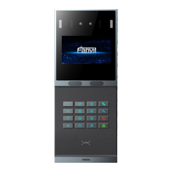
Product Overview Overview The i66 and i67 are newly designed facial recognition door phone by Fanvil. The product structure is crafted from aluminum alloy, with an explosion-proof rating of IK07. Featuring clear and thoughtful lines, the design provides users with a luxurious and elegant appearance, ensuring high-strength protection. -
Page 9: Installation Instructions
Installation Instructions Device Inventory Device Wall Bracket Mounting Template Screws, Terminal Blocks, and Tools RFID Card 2pcs Quick Installation Guide Installation Procedure 3.2.1 Wall-mounted... - Page 10 Wall-mounted: Step 1: Installation preparation 1,Check the following contents: • KM3*30 screw x3 • TA4 x 30mm screw x5 • φ6*30mm screw anchor x5 • KM4*30 screw x3 • TM6#*20/screw x5 • KM3*6mm screw x3 • KB2.6*5 screw x1 2,Tools required for installation •...
- Page 11 Avoid severe vibration, collisions, and impacts, as they may cause damage to internal precision components and the outer casing. When the device is powered on, if any abnormal conditions are detected, the power should be immediately disconnected until the issue is resolved. After the system is abnormally disconnected, please check according to the user manual.
- Page 12 Note: One cannot assume that biometric recognition products are 100% applicable to all identification scenarios. Step 3:Drilling 1,Paste the installation dimension drawing to the position to be installed. 2,Use an electric drill to drill the 4 holes marked on the mounting template. Remove the template when finishing drilling.
- Page 13 The wall bracket is separated from the device downwards, and use a screwdriver to loosen the 6 screws of the rear case Step 5 :Install the wall bracket, wiring and casing Align the screw holes of the wall bracket with the drilled holes on the wall, put in the φ6*30mm rubber plug, and fix it on the wall with the TA4*30mm screws provided.
-
Page 14: Flush Mounting
Connect the network cable with the RJ45 crystal head, and connect the power cable and the terminals of the electric lock control cable. Please refer to Section 2 for the connection sequence. Connect the connected terminals to the motherboard socket, see Section 2 for the connection location. - Page 15 • Built-in wall decorative panel x1 • Built-in wall bracket x2 • KM3*6mm screw x3 • PM3*3mm screw x5 • PM3*4mm screw x5 • φ6*30mm screw anchor x5 • M3*70mm screwdriver x1...
-
Page 16: User Guide
User Guide Button and Interface Instructions 4.1.1 i66 Button and Interface Instructions Number Name Description IP Camera Video signal acquisition and transmission ① Audio acquisition ② Infrared lamp Infrared Light Fill ③④... -
Page 17: I66 Standby Screen Instructions
RFID area Identification card ⑭ 4.1.2 i66 Standby Screen Instructions The following image is the default standby screen interface, representing the state of the user interface for most of the time. The description of icons is provided in Appendix I. -
Page 18: I67 Button And Interface Instructions
4.1.3 i67 Button and Interface Instructions Number Name Description IP Camera Video signal acquisition and transmission ① Audio acquisition ② Infrared lamp Infrared Light Fill ③④ When the lighting is insufficient and faces cannot be White Light Fill recognized, turn on the fill light for supplementary ⑤⑥... -
Page 19: Standby Screen Instructions
Standby Screen Instructions 4.2.1 i67 Standby Screen Instructions The following image is the default standby screen interface, representing the state of the user interface for most of the time. The description of icons is provided in Appendix Il. Number Description The function menu buttons allow switching between different functional... -
Page 20: Touchscreen Instructions(Only I67
123456. After entering the engineering settings, click on the application icon for the corresponding submenu to access it. i66 Menu: In standby mode, enter '#*107' to access the engineering settings. The initial password for the engineering settings is 123456. -
Page 21: Device Status
Account: Displays information about the registered account names/numbers on the device, including registration status and other details. Web Management 4.6.1 Device IP Address Retrieve Device IP through Scanning Tool: Connect the computer and i66/i67 to the same local network, and install Device Manager on the PC. -
Page 22: Web Interface
"admin." Language Settings Users can set the language for i66/i67 through both the device interface and the web interface. Upon initial startup under factory settings, the default language is English. Setting the language through the device menu interface: Access the device engineering settings menu, choose [Language], and proceed with language settings. - Page 23 The device supports two SIP accounts simultaneously, allowing registration based on application. Users can switch between the two SIP accounts as needed. Users can register SIP accounts through the device menu and the web interface. Registering an account through the device menu: Users can register SIP accounts through the device menu by navigating to [Accounts].They can switch between SIP lines, register a SIP account, and, after completing the SIP parameter settings, click "Save"...
-
Page 24: Calling Features
5.1.2 IP Call i66 IP Call 5.1.2.1 In standby mode, enter the IP address of the device you want to call. Replace the '.' in the IP address with the '*' key. After completing the input, press the [#] key to initiate the call. -
Page 25: Call Through Contacts
5.1.3 Call Through Contacts i66 Call Through Contacts 5.1.3.1 Reference: Speed Dial, Add Contact In standby mode, press the [Dial] key to enter the contact list. Use [2] or [8] to scroll up or down and select the desired contact to call. -
Page 26: Answer
Log in to the device web page, go to [Lines] >> [Basic Settings] >> [SIP P2P Settings], enable automatic answering, set the mode, and auto-answer time, then click submit. End The Call 5.3.1 i66 End The Call During a call, press the [Return] key to end the call. 5.3.2... -
Page 27: Advance Function
Advance Function MCAST This feature allows user to make some kind of broadcast call to people who are in multicast group. User can configure a multicast DSS Key on the phone, which allows user to send a Real Time Transport Protocol (RTP) stream to the pre-configured multicast address without involving SIP signaling. -
Page 28: Hotspot
cancels multicast monitoring in the system. Hotspot SIP hotspot is a simple utility. Its configuration is simple, which can realize the function of group vibration and expand the quantity of sip account. Take one device A as the SIP hotspot and the other devices (B, C) as the SIP hotspot client. - Page 29 Sets whether to enable the SIP hotspot function on the Line Settings corresponding SIP line Client Settings: As a SIP hotspot client, there is no need to set up a SIP account, which is automatically acquired and configured when the device is enabled. Just change the mode to "client" and the other options are set in the same way as the hotspot.
-
Page 30: Door Opening Operation
'Failed' message on the device along with a corresponding prompt tone. 7.1.2 Password i66: Click the [Unlock] button to access the password entry interface. Enter your User password and press '#' to unlock the door. A popup notification will appear upon... -
Page 31: Face
i67: Click on the icon displayed on the screen to access the password entry interface. Enter your User password and press to unlock the door. A popup notification will appear upon successful or unsuccessful attempts. Note: It's advisable to modify the default local door-opening password to a user-defined one during the initial setup. - Page 32 Click Add, click Upload on the Add User page, and select a local face photo to upload; the image supports jpg format, and the image size cannot exceed 100k Click the photo, WEB prompt "Photoing , Do not Upload photos perform other operations.", LCD screen will prompt "Take the photo in five seconds.", after the completion of the photo, the portrait will be displayed in the picture...
-
Page 33: User Management
access control calls the indoor unit to open the door, enter the DTMF password to open the door. Position speed dial. After this number is set, you can use Location this number to make calls When the number cannot be called, the call is forwarded Call Forward to the number Relay... -
Page 34: Add User
Add User 7.2.1.1 Supports adding user face information through the device menu. Enter the device menu (see "Configuration Menu Introduction" for details), and click on [Users]. Click the add button [+] Enter the name Click on the [Face], confirm agreement to collect the face information, face the ... -
Page 35: Search User
Search user 7.2.1.4 You can search for users by name 7.2.2 Import & Export If there are too many User and you cannot manually manage them one by one, you can import and export them in batches on the device web page. Import: Users can use the web page [Security Settings] >>... -
Page 36: Relay Settings
Effective Time: Time frame within each day when the period is effective, ranging from 00:00 to 23:59. Usage Example: Create a Period named 'Workdays,' set to repeat weekly from Monday to Friday, with an effective time span of 00:00 to 23:59 for those days. As shown in the picture. When adding cards, passwords, or portrait, select the Enabled Schedules. - Page 37 Parameters Value Description Monostable State: Defaulting to Monostable state, where the default is to keep the door closed. When a user opens the door, the lock opens and remains open for a set duration. After the timeout, it returns to the closed state.
-
Page 38: Door Sensor Settings
Parameters Value Description Card format displayed after using the built-in card reader. 8H10D , Card Format 8H10D: Decimal card number, conventional card 8HR10D display format. 8HR10D: Card number in reverse order. After a Wiegand card reader reads a card, the Wiegand Card 8H10D , displayed card format. - Page 39 status of the relay, door sensor, and control the relay via the web page [Security Settings] >> [Relay]. Relay Status: Parameters Value Description When the door sensor is enabled, if the door remains improperly closed after the timeout Check to following door unlock, signaling a mismatch Door Sensor 1/2 enable Door...
-
Page 40: Face Settings
Face Settings 7.5.1 Face Settings Users can set facial recognition parameters by navigating to [Facial Management] >> [Face Settings] on the web page. Parameters: Parameters Value Description For different scenarios, different biopsy models Highest, will be used to cope with "Close", "Normal" and Motion Detection Normal, "Highest"... -
Page 41: Prompts Settings
similarity will only go to the face database for comparison if it is greater than the set similarity degree. Standard mode is suitable for most scenarios. Performance mode has higher brightness and is Fill light brightness Standard suitable for darker or brighter environments. mode Performance If this mode is set to performance mode, the panel... -
Page 42: Monitoring Function
Monitoring function Access control systems can integrate with video surveillance systems such as NVR, VMS, etc. This section describes integration through RTSP and ONVIF protocols. RTSP The device enables the RTSP protocol by default, allowing users to integrate it into NVR, VMS, etc. -
Page 43: Contacts(Only I67)
Contacts(only i67) Contact(only i67) 9.1.1 Management Contacts Users can add, edit, and delete contacts through the web interface under [Contacts] >> [Contacts]. Contacts added via the web will synchronize and appear on both the web and device interfaces for viewing. Parameters Description Name... -
Page 44: Restricted Incoming Call List
Users can navigate to the web page [Contacts] >> [Advanced] >> [Import Contact List] to import contacts. It supports CSV, VCF, and XML formats. Users can first export a contact template (see exporting contacts operation), edit it, and then import. Exporting Contacts: Users can navigate to the web page [Contacts] >>... -
Page 45: Open The Door Record
10 Open The Door Record 10.1 Open The Door Record The log of door opening events is displayed. Click the Export button to select Save Target As to export the door opening records in CSV format. Parameters Description Relay Relay ID Result Display the result of a single door opening (success or failure) -
Page 46: Device Functions
11 Device Functions 11.1 Time Plan The Time Plan feature allows users to set specific actions to occur at either a particular time or within a period. A time point triggers an action at a specific moment, while a period triggers an action during a specified duration. -
Page 47: Maintenance
11.2 Maintenance 11.2.1 Configurations On this page, users with administrator privileges can view, export, or import the phone configuration, or restore the phone to factory Settings. Export Configurations Right click to select target save as, that is, to download the device's configuration file, suffix “.txt”... - Page 48 Basic Settings CPE Serial Number Display the device SN Configure the user name of FTP server; TFTP protocol does not need to be configured; if you use FTP protocol to Authentication Name download, if you do not fill in here, the default user of FTP is anonymous Authentication The password of provision server...
- Page 49 Configure DHCPv6 option, DHCPv6 option supports custom Custom Option Value option | option 66 | option 43, 3 methods to get the provision URL. The default is Disable. Custom Custom option number. Must be from 128 to 254. SIP Plug And Pay Whether enable PnP or not.
- Page 50 ACS Server URL ACS server address ACS User ACS server username ACS Password ACS server password Enable TR069 Warning If TR069 is enabled, there will be a prompt tone when Tone connecting. TLS Version TLS Version STUN Server Address Enable the STUN STUN Enable Enable TR069 after selection Month Start...
-
Page 51: Screen Settings
12 Screen Settings 12.1 Time/Date Users can set the time and date through the device web page and device menu. Set time/date on the device interface: Users can use the device menu [Display] >> [Time/Date] Set the device time/date. Web interface setting time/date: Users can use the web page [Intercom Settings] >>... -
Page 52: Screen Setting
Weekday Start The DST start weekday Hour Start The DST start hour Minute Start The DST start minute Month End The DST end month Week End The DST end week Weekday End The DST end weekday Hour End The DST end hour Minute End The DST end minute Manual Time... -
Page 53: Ui Settings
Password: The password interface serves as the default standby interface. Dialing: The dialing interface serves as the default standby interface. Face Recognition: The face recognition interface serves as the default standby interface. Operation interface (i66):The operation Guide page serves as the standby page. ... -
Page 54: Boot Logo
Bit Depth: 24 bits Note: The startup logo image must be created strictly according to the above requirements. Please take note of the following: For i66, rotate the image 90 degrees to the right before upgrading through the webpage. -
Page 55: Standby Logo
For i67, rotate the image 180 degrees before upgrading through the webpage. 12.3.3 Standby Logo The i66 device supports customizing the standby logo displayed in the upperleft corner of the standby interface. Users can upgrade custom standby logo images through the webpage: [System] >> [Upgrade] >> [Standby Logo]. -
Page 56: Tone Settings
Users can set the device volume through the device menu: [Display] >> [Media]. Web interface volume settings: Users can adjust the device volume through the web page: [Intercom Settings] >> [Media Settings] >> [Media Settings]. Volume parameters: Handsfree Ringtone: Adjusts the volume for incoming call ringtone and door opening ... - Page 57 Closed: Disables the call waiting tone. Default: Uses the default call waiting tone. Busy Tone Supports custom call waiting tones, which can be set by upgrading ringtone files under [System] >> [Upgrade] >> [Ring Upgrade], and then selecting the custom option for the call waiting tone.
- Page 58 Closed: No prompt tone after a failed card addition. Default: Uses the default prompt tone. Voice: Default builtin voice prompt, typically saying "Card addition failed." Issuing Failed Prompting Supports custom card addition failure prompt tones, which can be set by upgrading ringtone files under [System] >> [Upgrade] >>...
-
Page 59: Upload Ring
12.5.3 Upload Ring Users can upgrade ringtone files through the webpage: [System] >> [Upgrade] >> [Ringtone Upgrade]. Ringtone file format: Supports WAV and MP3. Maximum size for a single file :6 MB. ... -
Page 60: Network Settings
13 Network Settings 13.1.1 Ethernet Connection Users can configure the Ethernet network settings through the device webpage and device menu. The device defaults to using IPv4 mode, and users can refer to the network mode to modify the network settings. Setting up Ethernet Network via Web Interface: Users can access the webpage [Network] >>... -
Page 61: Network Server
13.3 Network Server Users can configure the network service type through the webpage: [Network] >> [Server Port]. Parameters Description Restart after setting takes effect. Optional web login as Web server type HTTP/HTTPS The default is 15 minutes, the timeout will automatically log Web login timeout out of the login page, and you need to log in again No need to enter the user name and password after the... -
Page 62: Security Settings
14 Security Settings 14.1 Short Circuit Input Short Circuit Input Detection Interface: Used to connect switches, infrared detectors, door magnets, vibration sensors, and other input devices. After a short circuit input is triggered, it can send a short message to a specified server address, or make a call to a designated number, and play a local alarm sound. -
Page 63: Relay Output
Enable or disable the input port from sending messages to the Triggered Behavior server. Triggered events: When connected to a door magnet, select Event door magnet; when connected to an indoor switch, select indoor switch. Triggered Ringtone Supports ringtone selection: None, no ringtone triggered. 14.2 Relay Output Relay Output Control Interface: Used to control electric locks, alarms, etc. -
Page 64: Tamper
On receiving the command ALERT = [command] from a remote device or server, if correct, it triggers/resets the corresponding output port. Input Trigger Choose whether the relay output port can be triggered by an input port. When the input port is configured as an indoor switch, and the corresponding input port is enabled here, the door can be triggered by the input port Whether to allow call state triggering of the relay. - Page 65 Tamper Alarm Reset Reset Alarm This button resets the tamper function to its default state. Status...
-
Page 66: Security
15 Security 15.1 Engineering Password Users can customize the engineering password by entering the webpage: [Intercom Settings] >> [Screen Settings] >> [LCD Menu Password Settings] interface for configuration. After changing the password, the new password must be used to access the device menu. -
Page 67: Web Filter
enter the new password to log in again. 15.3 Web Filter Users can configure to allow only machines from a specific IP subnet to access and manage the configuration of the device. Navigate to the webpage [Security] >> [Web Filter], add or delete allowed IP subnets. Configure the starting and ending IP addresses within the specified range, then click [Add] to apply the changes. -
Page 68: Trouble Shooting
16 Trouble Shooting When the device is not functioning properly, users can try the following methods to restore normal operation or collect relevant information to send a problem report to the technical support email. 16.1 Get device system information Users can obtain information through the device webpage [System] >> [Information] or the device [Menu] >>... -
Page 69: Screenshot
16.4 Screenshot If the device encounters issues, taking a screenshot can help technical support locate specific functions and understand the problem. To capture a screenshot, log in to the webpage, go to [System] >> [Tools] >> [Screenshot], click [Save BMP] (capture the problematic screen), save the image, and send it to technical support for issue resolution. - Page 70 1. Please check if the device is connected to the network. Verify if the device has an IP address. Check the system information; if the IP address is 0.0.0.0, it indicates that the device has not obtained an IP address. Ensure that the Device could not register network configuration is correct.
-
Page 71: Appendix
Clicking on this icon will take you to the contact list interface, where you can select a contact for calling. Contacts i66: Pressing this button initiates a call to the security guard. Dial: In standby mode, enter the number to initiate a call. Dail Click this icon to enter the Speed Dial List interface. -
Page 72: Appendix Iii Keyboard Character Query Table
Configure device network. Network Set device language. Language User adds face information User Set screen saver, volume, time/date. Display Register a SIP account. Account Perform a factory reset operation on the device. Factory Reset Perform a restart operation on the device. Reboot 17.3 Appendix III Keyboard character query table Delete entered characters, letters, or numbers. - Page 73 Number Switch to capital letter input mode. Capital Alphabet...
Need help?
Do you have a question about the i66 and is the answer not in the manual?
Questions and answers