Advertisement
Advertisement
Table of Contents

Related Manuals for Fanvil i68


Summary of Contents for Fanvil i68
- Page 1 V1.0 Smart Access Control Quick Installation Guide www.fanvil.com...
-
Page 2: Packaging List
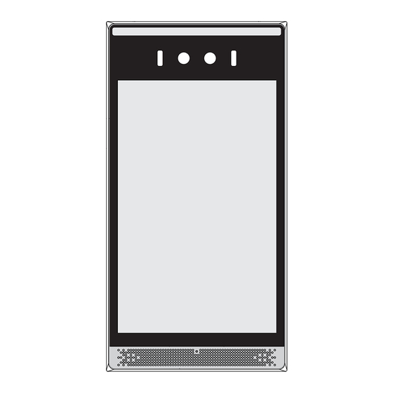
Packaging list KM2.5*8mm KM3*30mm TM6#*20mm Rubber stopper*5 Screw*3 Screw*3 Screw*5 Smart Access Wall mount TA4*25mm KM4*30mm IC Card*2 Quick Control Screw*5 Screw*3 Installation Guide Parts Introduction White light fill light Wall mount bracket hole RGB Camera Camera Infrared fill light Wall hole Microphone 8-inch display... -
Page 3: Installation Notes
Product wiring Electric control lock door open button connection method Smart access control terminal NC +12V S2 GND Electric lock Power Exit button Door status Note: This device is used as an independent access control host to connect to the electric lock and exit button. -
Page 4: Warranty Notice
After-sales warranty card In order to protect your rights, please be sure to fill in the following information truthfully Serial No E-mail User name Contact number Mailing address Where to buy Purchase date Fault phenomenon 【 】 Warranty Notice 【1】Within three months from the date of sale of the product, if there is a performance failure, the product itself and the outer packaging remain intact and free of scratches. -
Page 5: Wall Mounting
86 box ⑥ After aligning the holes of the i68 wall mount with the wall mount holes of the wall mount bracket, pull down slightly, lock the KM2.5*8 inner hexagon on both sides of the D hole as shown in the figure, and the installation is complete. - Page 6 Quick use process 1.Turn on the power and network, and enter the main page after the device is initialized. 2.The device will display the network IP address in the lower right corner: The network connection is normal: display the IP address currently obtained by the device. The network is not connected or faulty: 0.0.0.0 is displayed.
Need help?
Do you have a question about the i68 and is the answer not in the manual?
Questions and answers