Fanvil i51W User Manual
Hide thumbs
Also See for i51W:
- Quick installation manual (9 pages) ,
- Quick start manual (5 pages) ,
- How to reset (7 pages)
Table of Contents
Advertisement
Advertisement
Table of Contents

Subscribe to Our Youtube Channel
Related Manuals for Fanvil i51W


Summary of Contents for Fanvil i51W
- Page 1 User Manual Software Version: 1.0.0 Release Date:2020/06/15...
-
Page 2: Table Of Contents
Directory Directory.................................1 1 Picture..................................3 2 Table..................................4 Safety Instruction..............................5 3 Overview................................6 3.1 Overview..............................6 3.2 Product Introduction..........................6 4 Install Guide................................7 4.1 Use PoE or external Power Adapter....................... 7 5 Appendix Table..............................8 5.1 Appendix I - Icon............................ 8 6 Introduction to the User............................ 9 6.1 Instruction of Keypad..........................9 6.2 Idle Screen.............................10 6.3 Web Management.......................... - Page 3 9.5 System >> Upgrade..........................22 9.6 System >> Auto Provision........................24 9.7 System >> Tools........................... 24 9.8 System >> Reboot Phone........................24 9.9 Network >> Basic..........................24 9.10 Network >> Service Port........................24 9.11 Line >> SIP............................25 9.12 Line >> SIP Hotspot........................... 30 9.13 Line >>...
-
Page 4: Picture
1 Picture Picture 1 – Key Instruction........................9 Picture2 – Idle Screen..........................10 Picture3 – Login Page........................... 11 Picture4– AP Information........................12 Picture 5 – Line Registration.........................13 Picture 6 – Dialing Interface......................... 14 Picture 7– Incoming Call Interface....................15 Picture8 – Dialing Interface........................15 Picture 9 - Web Intercom configure...................... -
Page 5: Table
2 Table Table 1 – Model Configuration....................... 6 Table 2 - Keypad Icons..........................8 Table 3- Status Prompt and Notification Icons..................8 Table 4 - Key Instruction.........................9 Table 5 - Intercom configure......................... 17 Table 6 - MCAST Parameters on Web....................18 Table 7- SIP hotspot Parameters......................19 Table8 –... -
Page 6: Safety Instruction
Safety Instruction Please read the following safety notices before installing or using this unit. They are crucial for the safe and reliable operation of the device. Please use the external power supply that is included in the package. Other power supply may cause ... -
Page 7: Overview
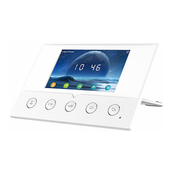
3 Overview 3.1 Overview Fanvil i51W is a 4.3-inch indoor station and i52W is a 7-inch indoor station, which support 8-way alarm input and industrial power socket input interface. It is mainly used in residential areas, villas, office buildings and other places to receive calls from the door phone, and communicate with the door phone, and achieve the remote access control. -
Page 8: Install Guide
PoE switch and power adapter at the same time, the power adapter will be used in priority and will switch to PoE power supply once it fails. Please use the power adapter supplied by Fanvil and the PoE switch met the specifications to ensure the device work properly. -
Page 9: Appendix Table
5 Appendix Table 5.1 Appendix I - Icon Table 2 - Keypad Icons Speed Dial Live View Open Door Return/End Answer Table 3- Status Prompt and Notification Icons Call out Call in Network Disconnected Auto-answering activated The Voice quality of calling The Voice encryption of calling Connecting WIFI Open SIP Hotspot... -
Page 10: Introduction To The User
6 Introduction to the User 6.1 Instruction of Keypad Picture 1 – Key Instruction The image above shows the device's key layout. Each key provides its own specific function. The user may refer to the key instructions in the illustrations in this section to operate the device. Some keys can be long pressed. -
Page 11: Idle Screen
Return to the parent directory Answer Key Answer the call 6.2 Idle Screen Picture2 – Idle Screen The figure above shows the default standby screen, which is what the user interface looks like most of the time. The upper half of the home screen displays the welcome message, time and date, and status information (such as automatic response, network connection status, etc.). -
Page 12: Network Configurations
"admin". Refer to the 10 Page Configuration for details on how to operate the page 6.4 Network Configurations Fanvil i51W &i52W support two network connection modes: wired network connection and wireless network connection. Users should choose the corresponding connection mode according to their own situation. -
Page 13: Wireless Network
mask, gateway, and primary and secondary DNS servers. This usually applies to some professional web user environments. The default configuration of the device is the automatically configured network mode 6.4.2 WLAN If there is no wired network, you can connect to the background web page of the device by turning on the AP mode of the device and set up the wireless network connection. -
Page 14: Lines Configuration
6.5 Lines Configuration At least one line of equipment must be configured correctly to provide telephone service. The line configuration works like a virtual SIM card that holds a mobile phone with service provider and telephone account authentication. When the device applies these configurations, the device automatically registers with a stored information provider, just as you can insert a SIM card into any mobile phone, and the phone USES the information in the SIM card to apply services, rather than the phone itself. -
Page 15: Basic Function
7 Basic Function 7.1 Call The DSS key for webpage setting is the memory key, the type is speed dial, the value is the number to call, the line is set as the registered line, and the media is set as the default, as shown below: After setting, press the button to exhale, and the exhale interface is as follows: Picture 6 –... -
Page 16: Unlock
Picture 7 – Incoming Call Interface The user can answer the phone by pressing the button . To reject a call, the user presses the button 7.3 Unlock The DSS key for webpage setting is DTMF, and the value is the opening password for the caller of access control You can open the door by pressing the button while talking. - Page 17 1) Press 2) Press...
-
Page 18: Advanced Function
8 Advanced Function 8.1 Intercom When the Intercom is enabled, it can automatically receive calls from the intercom. Picture 9 - Web Intercom configure Table 5 - Intercom configure Parameter Description Enable Intercom When intercom is enabled, the device will accept the incoming call request with a SIP header of Alert-Info instruction to automatically answer the call after specific delay. - Page 19 Picture 10 - Multicast Settings Page Table 6 - MCAST Parameters on Web Parameters Description Normal Call Priority Define the priority of the active call, 1 is the highest priority, 10 is the lowest. Enable Page Priority The voice call in progress shall take precedence over all incoming paging calls.
-
Page 20: Sip Hotspot
8.3 SIP Hotspot SIP hotspot is a simple but practical function. With simple configurations, the SIP hotspot function can implement group ringing. SIP accounts can be expanded. Phone set functions as a SIP hotspot and other phone sets (B and C) function as SIP hotspot clients. - Page 21 Configure SIP hotspot server: Picture 12 - SIP hotspot server configuration Configure SIP hotspot client: To set as a SIP hotspot client, no SIP account needs to be set. The Phone set will automatically obtain and configure a SIP account. On the SIP Hotspot tab page, set Mode to Client. The values of other options are the same as those of the hotspot.
-
Page 22: Web Configurations
9 Web Configurations 9.1 Web Page Authentication The user can log into the web page of the phone to manage the user's phone information and operate the phone. Users must provide the correct user name and password to log in. 9.2 System >>... -
Page 23: System >> Upgrade
Clear Configurations Select the module in the configuration file to clear. SIP: account configuration. AUTOPROVISION: automatically upgrades the configuration TR069:TR069 related configuration MMI: MMI module, including authentication user information, web access protocol, etc. DSS Key: DSS Key configuration Clear Tables ... - Page 24 Table8 – Online Upgrade Parameter Parameter Description Upgrade Service Fill in the address of the available primary upgrade server (HTTP Upgrade Service Address 1 server). Fill in the address of the available backup upgrade server (HTTP Upgrade Service Address 2 server) and request the backup server when the primary server is unavailable.
-
Page 25: System >> Auto Provision
The Auto Provision settings help IT manager or service provider to easily deploy and manage the devices in mass volume. For the detail of Auto Provision, please refer to this link Auto Provision Description。 https://www.fanvil.com/Support/download/cid/14.html 9.7 System >> Tools Tools provided in this page help users to identify issues at trouble shooting. Please refer to Trouble Shooting for more detail. -
Page 26: Line >> Sip
Table 9 - Service port Parameter Description Web Server Type Reboot to take effect after settings. Optionally, the web page login is HTTP/HTTPS. Web Logon Timeout Default as 15 minutes, the timeout will automatically exit the login page, need to login again. Web auto login After the timeout does not need to enter a user name password, will automatically login to the web page. - Page 27 Transport Protocol Set up the SIP transport line using TCP or UDP or TLS. Registration Expiration Set SIP expiration date. SIP Server 2 Server Address Enter the IP or FQDN address of the SIP server Server Port Enter the SIP server port, default is 5060 Transport Protocol Set up the SIP transport line using TCP or UDP or TLS.
- Page 28 enabled, the device will receive notification from the server if there is voice message waiting on the server Voice Message Number Set the number for retrieving voice message Voice Message Subscribe Period Set the interval of voice message notification subscription Enable Hotline Enable hotline configuration, the device will dial to the specific number immediately at audio channel opened by off-hook handset or turn on...
- Page 29 Unconditional Disable Call Forward Set the feature code to dial to the server Unconditional Enable Call Forward on Busy Set the feature code to dial to the server Disable Call Forward on Busy Set the feature code to dial to the server Enable Call Forward on No Set the feature code to dial to the server Answer...
- Page 30 IP address, not the address in via field. Convert URI Convert not digit and alphabet characters to %hh hex code Use Quote in Display Name Whether to add quote in display name, i.e. “Fanvil” vs Fanvil Enable GRUU Support Globally Routable User-Agent URI (GRUU) Sync Clock Time...
-
Page 31: Line >> Sip Hotspot
Flash Info Content-Type Set the SIP info content type. Flash Info Content-Body Set the SIP info content body. PickUp Number Set the scramble number when the Pickup is enabled. JoinCall Number Set JoinCall Number. Intercom Number Set Intercom Number. Unregister On Boot Whether to enable logout function. -
Page 32: Line >> Basic Settings
Video streaming information. User Agent Set user agent information 9.14 Line >> Basic Settings Set up the register global configuration. Table 12- Set the line global configuration on the web page Parameters Description STUN Settings Server Address Set the STUN server address Server Port Set the STUN server port, default is 3478 Binding Period... - Page 33 Restrict Active URI Source IP Set the device to accept Active URI command from specific IP address. More details please refer to this link https://www.fanvil.com/Support/download/cid/14.html。 Line Display Format Custom line format:SIPn/SIPn:xxx/xxx@SIPn Configure a special character &, the number of the other party is 78&9, Call number filtering the call will be filtered out &...
-
Page 34: Settings >> Media Settings
Play Dialing DTMF Tone Play DTMF tone on the device when user pressed a phone digits at dialing, default enabled. Play Talking DTMF Tone Play DTMF tone on the device when user pressed a phone digits during taking, default enabled. DND Settings DND Option Select to take effect on the line or on the phone or close. -
Page 35: Settings >> Mcast
DTMF Payload Type Enter the DTMF payload type, the value must be 96~127. Opus playload type Set Opus load type, range 96~127. Set Opus sampling rate, including opus-nb (8KHz) and opus-wb (16KHz). OPUS Sample Rate ILBC Payload Type Set the ILBC Payload Type, the value must be 96~127. ILBC Payload Length Set the ILBC Payload Length Enable MWI Tone... -
Page 36: Settings >> Action
9.18 Settings >> Action Action URL Note! Action urls are used for IPPBX systems to submit phone events. Please refer to Fanvil Action URL for details. https://www.fanvil.com/Support/download/cid/14.html 9.19 Settings >> Time/Date The user can configure the time Settings of the phone on this page. -
Page 37: Settings >> Time Management
Week Start The DST start week Weekday Start The DST start weekday Hour Start The DST start hour Minute Start The DST start minute Month End The DST end month Week End The DST end week Weekday End The DST end weekday Hour End The DST end hour Minute End... -
Page 38: Settings >> Advanced
You can either select the country area or customize the area. If the area is selected, it will bring out the following information directly. If you choose to customize the area, you can modify the button tone, call back tone and other information. Picture 17 - Tone settings on the web 9.22 Settings >>... -
Page 39: Call List >> Web Dial
Allowed Incoming Calls: When DND is enabled, the incoming call number can still be called. Restricted Outgoing Calls: Adds a number that restricts outgoing calls and cannot be called until the number is removed from the table. 9.24 Call List >>... -
Page 40: Security >> Web Filter
Picture 18 - IP Camera List 9.26 Security >> Web Filter The user can set up a configuration management phone that allows only machines with a certain network segment IP access. Picture 19- Web Filter settings Picture 20 - Web Filter Table Add and remove IP segments that are accessible;... -
Page 41: Security >> Trust Certificates
9.27 Security >> Trust Certificates Set whether to open license certificate and general name validation, select certificate module. You can upload and delete uploaded certificates. Picture 21 - Certificate of settings 9.28 Security >> Device Certificates Select the device certificate as the default and custom certificate. You can upload and delete uploaded certificates. -
Page 42: Device Log >> Device Log
9.29 Device Log >> Device Log You can grab the device log, and when you encounter an abnormal problem, you can send the log to the technician to locate the problem. See 11.6 Get log information. 9.30 Security Settings Picture 23- Security Settings Table 19 –... - Page 43 When the high-level trigger (disconnect trigger) is selected, the input port (high level) disconnect trigger is detected. Send short Send Short Messages enables or disables input ports to Send messages to the server messages When set to DSSKey1 or DSSKey2, the DSS key is triggered for the call, which DSS keys defaults to NONE Ring Trigger...
-
Page 44: Trouble Shooting
10 Trouble Shooting When the phone is not in normal use, the user can try the following methods to restore normal operation of the phone or collect relevant information and send a problem report to Fanvil technical support mailbox. 10.1 Receive the System Info of Device Users can enter the menu interface by long pressing. -
Page 45: Network Packets Capture
Picture 24- Screenshot 10.5 Network Packets Capture Sometimes it is helpful to dump the network packets of the device for issue identification. To get the packets dump of the device, user needs to log in the device web portal, open page [System] >>... -
Page 46: Get Log Information
User may examine the packets with a packet analyzer or send it to Fanvil support mailbox. 10.6 Get Log Information Log information is helpful when encountering an exception problem. In order to get the log information of the phone, the user can log in the phone web page, open the page [Device log], click the [Start] button, follow the steps of the problem until the problem appears, and then click the [End] button, [Save] to local analysis or send the log to the technician to locate the problem.
Need help?
Do you have a question about the i51W and is the answer not in the manual?
Questions and answers