Table of Contents
Advertisement
Quick Links
Advertisement
Table of Contents

Subscribe to Our Youtube Channel
Related Manuals for Fanvil i56A


Summary of Contents for Fanvil i56A
- Page 1 User Manual Software Version: 1.0.0 Release Date:2020/10.26...
-
Page 2: Table Of Contents
3 FCC Statement............................... 11 4 Safety Instruction............................12 5 Overview................................13 5.1 Overview..............................13 5.2 Product Introduction.......................... 13 5.2.1 i56A Physical specifications....................13 6 Install Guide..............................17 6.1 Use PoE or external Power Adapter....................17 6.2 Installation(two models).......................18 7 Appendix Table.............................. 21 7.1 Appendix I - Icon..........................21 7.2 Appendix II –LED Definition...................... - Page 3 9.7 Auto-Answering..........................40 9.8 Call Back............................. 42 9.9 Mute..............................43 9.9.1 Mute the Call..........................43 9.9.2 Ringing Mute..........................44 9.10 Call Hold/Resume..........................45 9.11 DND..............................46 9.12 Call Forward............................. 48 9.13 Call Transfer............................. 50 9.13.1 Blind transfer........................... 50 9.13.2 Semi-Attended transfer......................51 9.13.3 Attended transfer........................
- Page 4 11.1 Basic Settings...........................81 11.1.1 Language..........................81 11.1.2 Time & Date..........................82 11.1.3 Screen............................84 11.1.3.1 Screen Saver....................... 84 11.1.4 Ring............................85 11.1.5 Voice Volume.......................... 85 11.1.6 Reboot............................85 11.2 Phone book............................86 11.2.1 Local contact........................... 86 11.2.1.1 Add / Edit / Delete Contact..................87 11.2.1.2 Add / Edit / Delete Group...................88 11.2.2 Black list...........................
- Page 5 12.7 System >> Tools..........................60 12.8 System >> Reboot Phone......................60 13 Network >> Basic............................62 13.1 Network >> Service Port........................ 62 13.2 Network >> Advanced........................63 13.3 Line >> SIP............................63 13.4 Line >> SIP Hotspot........................69 13.5 Line >> Dial Plan..........................69 13.6 Line >>...
- Page 6 14.5 Network Packets Capture......................95 14.6 Get Log Information........................96 14.7 Common Trouble Cases........................ 96...
-
Page 7: Picture
1 Picture Picture 1 -Panel description......................14 Picture 2 -Interface Description..................... 15 Picture 3 -External device connection diagram................16 Picture 4 -Equipment Support......................18 Picture 5 -Wall Mount 1........................18 Picture 6 -Wall Mount 2........................19 Picture 7 - Connecting to the Device.................... 19 Picture 8 - Desktop phone installation..................20 Picture 9 -Default home screen..................... - Page 8 Picture 37 - Select the line to set up call forwarding..............49 Picture 38 - Select call forward type..................... 49 Picture 39 - Set call forward......................50 Picture 40 - Transfer interface......................51 Picture 41 - Semi-Attended transfer....................51 Picture 42 - Attended transfer......................52 Picture 43 - Call waiting setting.....................
- Page 9 Picture 75 - New Voice Message Notification................76 Picture 76 - Voice message interface................... 77 Picture 77 - Configure voicemail number..................77 Picture 78 - Register SIP account....................78 Picture 79 - SIP hotspot server configuration................79 Picture 80 - SIP hotspot client configuration................79 Picture 81 - Phone language setting.....................81 Picture 82 - Language setting on Web page................
- Page 10 Picture 113 - Custom setting of dial - up rules................70 Picture 114 - Dial rules table (1)....................71 Picture 115 - Dial rules table (2)....................72 Picture 116 - Tone settings on the web..................81 Picture 117 - Web cloud phone book Settings................83 Picture 118 -IP Camera List......................87 Picture 119 - Web Filter settings....................88 Picture 120 - Web Filter Table......................
-
Page 11: Table
2 Table Table 1 - Interface Description....................... 15 Table 2 - Status Prompt and Notification Icons................21 Table 3 - DSSkey Icons........................22 Table 4 - DSS KEY LED State....................... 25 Table 6 - BLF Function key subtype parameter list..............64 Table 7 - Agency mode........................70 Table 8 - Intercom configure......................71 Table 9 - MCAST Parameters on Web.................. -
Page 12: Fcc Statement
3 FCC Statement This equipment has been tested and found to comply with the limits for a Class B digital device, pursuant to part 15 of the FCC Rules. These limits are designed to provide reasonable protection against harmful interference in a residential installation. This equipment generates uses and can radiate radio frequency energy and, if not installed and used in accordance with the instructions, may cause harmful interference to radio communications. -
Page 13: Safety Instruction
4 Safety Instruction Please read the following safety notices before installing or using this unit. They are crucial for the safe and reliable operation of the device. Please use the external power supply that is included in the package. Other ... -
Page 14: Overview
Still, the document might not be up to date with the newly release software, so please kindly download updated user manual from Fanvil website, or contact with Fanvil support if you have any question using i56A. 5.2 Product Introduction i56A Physical specifications 5.2.1... - Page 15 Picture 1 -Panel description Interface description There are some interfaces on the back of the device for connecting power supply, alarms etc. The connections are as follows:...
- Page 16 Picture 2 -Interface Description Table 1 - Interface Description External device connection diagram...
- Page 17 Picture 3 -External device connection diagram...
-
Page 18: Install Guide
6 Install Guide 6.1 Use PoE or external Power Adapter I56A, called as ‘the device’ hereafter, supports two power supply modes, power supply from external power adapter or over Ethernet (PoE) complied switch. PoE power supply saves the space and cost of providing the device additional power outlet. -
Page 19: Installation(Two Models
6.2 Installation(two models) Picture 4 -Equipment Support Model 1. Wall-mounted Installation Step 1. Install wall bracket Without 86 embedded box in the wall A. According to the position of the cable in the wall, dig out a square hole (height*width*depth=65.5*50.5*50mm) that can accommodate all cables. B. - Page 20 B. Fix the wall bracket on the 86 embedded box with two PM4*16mm screws. Picture 6 -Wall Mount 2 Step 2. Connect peripherals A. If you need to connect other input and output devices, please connect to the host through the cable. Step 3.
- Page 21 the bracket up to complete the installation. Picture 8 - Desktop phone installation...
-
Page 22: Appendix Table
7 Appendix Table 7.1 Appendix I - Icon Table 2 - Status Prompt and Notification Icons Icons Description Call out Call in Call Hold Network Disconnected Call forward activated Auto-answering activated Hands-free (HF) Mode Headphone (HP) Mode Handset (HS) Mode Mute Microphone HD Audio The Voice encryption of calling... - Page 23 SIP Hotspot Connecting WIFI Open Bluetooth Unread voice message USB insert tips Table 3 - DSSkey Icons Icons Description Speed Dial Intercom Call Park Call forward Key Event/DND Key Event/Call Hold Key Event/Call Transfer Key Event/Phonebook Key Event/Redial Key Event/Pickup...
- Page 24 Key Event/Join Key Event/Auto Redial On Key Event/Auto Redial Off Key Event/Call Forward Key Event/Call Logs Key Event/Flash Key Event/ Key Event/Headset Key Event/Release Key Event/Lock Phone Key Event/SMS Key Event/Call Back Key Event/Hide DTMF Key Event/Power Light Key Event/Prefix Key Event/Hot Desking Key Event/Agent Key Event/End...
- Page 25 Key Event/Escalate Key Event/Trace Key Event/Handfree Key Event/Answer Key Key Event/Private Hold URL & Action URL BLF List Multicast Unfold Collapse...
-
Page 26: Appendix Ii -Led Definition
7.2 Appendix II –LED Definition Type LED Light LED State Line Key Line inactive Green On Line ready (Registered) Green Blinking Ringing Red Blinking Line is trying to register Red Blinking Line error (Registration failure) Red On Dialing/Line in use (Talking) Yellow Blinking Call holding Green On... -
Page 27: Introduction To The User
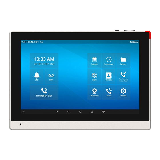
8 Introduction to the User 8.1 Idle Screen Picture 9 -Default home screen The image above shows the default standby screen, which is the user interface in the most of the time. The main screen displays the frequently used function menu buttons of the device. It is also the first layer of the function menu buttons. -
Page 28: Dial
8.3 Dial Dial: The user can press the dialer key to dial, and the sound will be played from the speaker. Line dial: The user can also use the line key to specify the line to make/receive calls. 8.4 Screen Touch Instructions The device can be configured and operated by touching the screen. - Page 29 Hardware Version number Software Version number Phone Storage(RAM and ROM) System Running Time Android Version SIP Account Information: SIP Account SIP Account Status (registered / uncommitted / trying / time out) The user can view the phone status through the phone interface and the web interface.
-
Page 30: Web Management
Picture 11 -WEB phone status 8.6 Web Management Phone can be configured and managed on the web page of the phone. The user needs to enter the IP address of the phone in the browser at first and open the web page of the phone. -
Page 31: Network Configurations
page, please refer to page 11 Web configurations. 8.7 Network Configurations The device supports two kinds of network connection modes: wired network connection and wireless network connection. This section describes the wired network connection. For wireless network connection, refer to 10.5 wi-fi. - Page 32 authentication. When the device is applied with the configuration, it will register the device to the service provider with the server’s address and user’s authentication as stored in the configurations. The user can conduct line configuration on the interface of the phone or the webpage, and input the corresponding information at the registered address, registered user name, registered password and SIP user, display name and registered port respectively, which are provided by the SIP server administrator.
- Page 33 Picture 14 - Phone display name and port WEB interface:After logging into the phone page, enter [Line] >> [SIP] and select SIP Line for configuration, click apply to complete registration after configuration, as shown below: Picture 15 - Web SIP registration...
-
Page 34: Basic Function
9 Basic Function 9.1 Making Phone Calls Default Line The device provides six line services. If all lines are configured, user can make or receive phone calls on either line. If default line is configured by user, there will be a default line to be used for making outgoing call which is indicated on the top left corner. - Page 35 with the default line. Picture 17 - Dial number...
-
Page 36: Answering Calls
Cancel Call While calling the number, user can press to end the call with [End] button. Picture 18 - Call number 9.2 Answering Calls when the phone is idle and there is a call, the user will see the call reminder screen as below. -
Page 37: Talking
Picture 19 - Answering calls User can answer the call by press the [Answer] button. To divert the incoming call, user should press [Divert] button. To reject the incoming call, user should press [Reject] button. Talking 9.2.1 When the call is connected, user will see a talking mode screen as the following figure. -
Page 38: Make / Receive The Second Call
Picture 20 - Talking interface Table 9 - Talking mode Number Name Description The current line The line currently used by the phone. ① Default display, user can customize the selection of User avatar ② avatar pictures. The name or number of the person on the other end of Calls to end ③... - Page 39 Picture 21 - The second call interface Second Outgoing Call To make a second call, user may press [Xfer] / [Conf] button to make a new call on the default line. Then dial the number the same way as making a phone call. Another alternative for making second call is to pressing DSS Keys dial out from the configured Keys (BLF/Speed Dial).
-
Page 40: End Of The Call
After the user finishes the call, the user can press softkey [End] key to end the call. 9.4 Video Call i56A supports a variety of video formats QVGA,CIF,VGA,4CIF,720P,1080p。 The device only supports video decoding, but users can initiate video calls. -
Page 41: Redial
Picture 24 - Video Settings 9.5 Redial Redial the last outgoing number: Set the function key as redial key. When the phone is in standby mode, press the redial key to call out the last number dialed. 9.6 Dial-up Query Phone is defaulted to open the dial-up inquiry function, dial-out, enter two or more Numbers, dial the interface will automatically match call records, contacts in the number list, touch the number that you select to call out. - Page 42 Phone interface: Press [ Settings] >>[Advanced]>> [Account] >> [Line] ; Press the button to select the line and enter the [Basic Settings]. Click on/off the auto answering option and set the auto answering time. The default is 5 seconds.The icon in the upper left corner of the screen indicates that auto answer is enabled.
-
Page 43: Call Back
Picture 26 - Web page to start auto-answering 9.8 Call Back The user can dial back the last call. If there is no call history, press the [Callback] button and the phone will say "can't process". Set the callback key through the phone interface: ... -
Page 44: Mute
Set the callback key through the web interface: Log in the phone page, enter the [Function Key] >> [Function Key] page, select the function Key, set the type as the function Key, and set the subtype as the callback, as shown in the figure: Picture 28 - Set the callback key on the web page 9.9 Mute You can turn on mute mode during a call and turn off the microphone so that the local... -
Page 45: Ringing Mute
Picture 29 - Mute the call Cancel mute: press cancel mute on the phone again. The mute icon is no longer displayed in the call screen. Ringing Mute 9.9.2 Mute: press the mute button when the phone is ringing: ... -
Page 46: Call Hold/Resume
Picture 30 - Ringing mute Cancel ring tone mute: On the incoming call screen, press the mute button again or volume up button to cancel ring tone mute. It will no longer shows mute icon in upper right corner after cancel .The phone mute icon is off 9.10 Call Hold/Resume... -
Page 47: Dnd
Picture 31 - Call hold interface 9.11 DND User may enable Do-Not-Disturb (DND) feature on the device to reject incoming calls (including call waiting). The DND can be enabled on line basis. Enable/Disable phone all lines DND, Methods the following: Phone interface:Default standby mode,... - Page 48 1) Press [ Settings] >>[DND] button, Enter the [DND] editing interface. 2) select the line to adjust the mode and state of "do not disturb". 3) The user will see the DND icon turn red, and the sip-line has enabled the mode of "DND".
-
Page 49: Call Forward
Picture 35 - DND Settings The user turns on the DND for a specific route on the web page:Enter [Line] >> [SIP], select a [Line] >> [Basic settings], and enable DND. Picture 36 - Line DND 9.12 Call Forward Call forward is also known as ‘Call Divert’ which is to divert the incoming call to a specific number based on the conditions and configurations. - Page 50 Picture 37 - Select the line to set up call forwarding 2) Select the line to be set and enter the call forward settings interface Picture 38 - Select call forward type 3) Click the slide button to select on/off. 4) Configure parameters by clicking Settings and enter the required information.
-
Page 51: Call Transfer
Picture 39 - Set call forward 9.13 Call Transfer When the user is talking with a remote party and wish to transfer the call to another remote party, there are three ways to transfer the call, blind transfer, attended transfer and Semi-Attended transfer. -
Page 52: Semi-Attended Transfer
Picture 40 - Transfer interface Semi-Attended transfer 9.13.2 During the call, the user presses the function menu button [transfer] to input the number to be transferred, and then press the call button. When the third party is not answered, press the transfer on the call interface to make the semi-attendance transfer or press the end button to cancel the semi-attendance transfer. -
Page 53: Attended Transfer
Attended transfer 9.13.3 Attendance transfer is also known as "courtesy mode", which is to transfer the call by calling the other party and waiting for the other party to answer the call. Calling is the same procedure. In dual call mode, press the "transfer" button to transfer the first call to the second call. - Page 54 Picture 43 - Call waiting setting WEB interface: Enter [Phone Settings] >> [Features] >> [Basic Settings], enable/disable call waiting and call waiting tone. Picture 44 - Web call waiting setting...
-
Page 55: Conference
Picture 45 - Web call waiting tone setting 9.15 Conference Local Conference 9.15.1 To conduct local conference, the user needs to log in the webpage and enter [Line] >> [SIP] >> [Basic settings]. The meeting mode is set as local (the default is local mode), as shown in the figure: Picture 46 - Local conference setting Two ways to create a local conference:... -
Page 56: Network Conference
Picture 47 - Local conference ( 1 ) 2) If the device has a call all the way, press the conference key in the call interface, enter the number to join the meeting and press the call; After the opposite end is answered, press the conference button again to set up the local tripartite conference:... -
Page 57: Call Park
Picture 49 - Network conference Method to join a network conference: Call the numbers of network conference and when they enter the password then will enter the conference room. The two phones have established common calls. Press the conference button ... -
Page 58: Pick Up
Picture 50 - Phone set call park Picture 51 - WEB set call park 9.17 Pick Up Picking-up requires server support. Consult your system administrator for support. You can use the Pick Up function to answer incoming calls from other users. The phone can pick up incoming calls by configuring DSSkey for BLF and setting the Pick Up code. - Page 59 subscription number, and pick up code Other phones call the subscription number, and the opposite end is in the incoming ring. Press the DSS key to pick up the phone. The caller picks up the call and speaks to it. ...
-
Page 60: Anonymous Call
Picture 53 - WEB pick up setting 9.18 Anonymous Call Anonymous Call 9.18.1 The phone can set up anonymous calls to hide the calling number and the calling name. You can see anonymity in the context of [Settings] >> [Account] >> [Line] >> ... - Page 61 Picture 54 - Enable anonymous call On the web page [Line] >> [SIP] >> [Advanced Settings] can also open anonymous calls. Setting to enable anonymous calls also corresponds to the SIP line. That is, the setting under the SIP1 page can only take effect on the SIP1 line. Picture 55 - Enable Anonymous web page call The following is a transcript of an anonymous call received by the phone.
-
Page 62: Ban Anonymous Call
Picture 56 - Anonymous call log Ban Anonymous Call 9.18.2 The device can be set to prohibit anonymous calls, that is anonymous calls to the number will be directly rejected. In the phone [Settings] >> [Account] >> [Line] >> [Advanced Settings] >> ... - Page 63 Picture 58 - Page Settings blocking anonymous call...
-
Page 64: Advance Function
10 Advance Function 10.1 BLF (Busy Lamp Field) Configure the BLF Functionality 10.1.1 Page interface: log in the phone page, enter the [Function key] >> [Function key] page, select a DSS key, set the function key type as memory key, choose subtype among BLF/NEW CALL, BLF/BXFER, BLF/AXFER, BLF/CONF, set BLF/DTMF value as the number which is subscribed, set the corresponding SIP line. -
Page 65: Use The Blf Function
Picture 60 - Phone configuration BLF function key Table 6 - BLF Function key subtype parameter list Subtype Standby is described Calling is described BLF/NEW Pressing while When you press this BLF key while talking to CALL standby to dial the subscriber another user, you create a new call along number. -
Page 66: Blf List
subscribed object and is used by the server to pick up the call. BLF helps you monitor the other person's status (idle, ringing, talking, off). BLF function: Monitor the status of subscribed phones. Call the subscribed number. Transfer calls to the subscribed number. ... -
Page 67: Record
Picture 61 - Configure the BLF List functionality Use the BLF List function: when the configuration is completed, the phone will automatically subscribe to the contents of the BLF List group. Users can monitor, call and transfer the corresponding number by pressing the BLF List key. Picture 62 - BLF List number display 10.3 Record The device supports recording during a call. -
Page 68: Local Record
Local Record 10.3.1 When using local recording, it is necessary to start recording on the phone page [Application] >> [Manage recording], select the local type and set the voice coding. The webpage is as follows: Picture 63 - WEB local recording Local recording steps: Open the recording on the web page, and set the recording type as local recording. -
Page 69: Server Record
The web is as follows: Picture 64 - Web server recording Note: to be used with Fanvil recording software. Call Recording Configuration Please refer to the documentation for specific usage: and Use Description http://www.fanvil.com.cn/Uploads/Temp/download/20180928/5badccd249853.pdf... -
Page 70: Agent
Picture 65 - Web SIP info recording 10.4 Agent Agent (Agent function) of the phone can be realized: when multiple people use a device for Agent services at different times, he or she can quickly register his or her SIP account on the same server. - Page 71 Picture 67 - Configure the proxy account-hotel Guest mode Table 7 - Agency mode Parameter Description Normal mode Number Set the proxy account number. User Set the proxy account number to verify the user name. Password Set the proxy account number to verify the password. Line Select the SIP line.
-
Page 72: Intercom
out of the SIP account. Picture 68 - Agent logon page 10.5 Intercom When the Intercom is enabled, it can automatically receive calls from the intercom. Picture 69 - Web Intercom configure Table 8 - Intercom configure Parameter Description Enable Intercom When intercom is enabled, the device will accept the incoming call request with a SIP header of Alert-Info instruction to automatically answer the call after specific delay. -
Page 73: Mcast
Tone Enable Intercom Barge by selecting it, the phone auto answers the intercom Enable Intercom call during a call. If the current call is intercom call, the phone will reject the Barge second intercom call 10.6 MCAST This feature allows user to make some kind of broadcast call to people who are in multicast group. -
Page 74: Sca(Shared Call Appearance
Users need the support of server end to use SCA function. You can refer to http://www.fanvil.com/Uploads/Temp/download/20180920/5ba38181e4e4b.pdf 1) Configure on Phone When registering with the BroadSoft server, a Fanvil Phone can register the account created previously on multiple terminals. Picture 71 - Register BroadSoft account After the phone registers on the BroadSoft server, a server type needs to be set.
Need help?
Do you have a question about the i56A and is the answer not in the manual?
Questions and answers