Advertisement
Quick Links
Advertisement

Related Manuals for Fanvil i31S


Summary of Contents for Fanvil i31S
- Page 1 WWW.FANVIL.COM Video Door Phone Quick Installation Guide...
-
Page 3: Table Of Contents
Table of Contents 1. Package Contents ..................4 2. Physical Specifications .................. 4 3. Installation ....................8 4. Searching Door Phone ................11 5. SIP Door Phone Setting ................12 6. Door Unlocking Setting ................13... -
Page 4: Package Contents
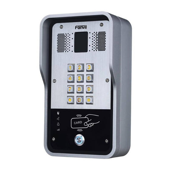
Package Contents Connectors Door Phone Quick Installation Mounting Template Guide Screw and RFID Cards Wrench Physical Specifications Device size 223 x 130 x 74mm Weight 1800g Front Panel Infrared light Speaker Camera photoresistor Numeric keypad (password and dialing) Lock status Call status RFID area Ring status... - Page 5 Interface Description Camera Get the video. Infrared light & The Compensate for lack of ambient light Photoresistor The door phone has a built-in speaker for convenient communication Speaker and alert use. The door phone has a built-in microphone hidden in the pinhole located on the front panel.
- Page 6 Network Connector Power and Electric-lock Connector +DC12V S-IN S-OUT 12V DC Input Electric-lock switch Indoor switch JP1 Jumper There are two modes for power supply of electric-lock as shown in the picture below. (The default is “Passive Mode:”). Passive Mode: When the electric-lock starting current is more than 12V/650mA, need to use the external drive mode, the electric lock interface for short circuit output control.
- Page 7 Wiring instructions NO: Normally Open Contact COM: Common Contact NC: Normally Close Contact Driving Mode Electric-lock Mode Connections No electricity Electrify Jumper Active Passive when open when open √ √ √ √ √ √ √ √ √ √...
-
Page 8: Installation
3. Installation Front Panel Main Part of Intercom Rain Shade Back Panel Figure 1 Three Major Parts of i31S Step 1: Installation preparation A. Check the following contents: Hex wrench x 1 RJ45 plugs x 2 (1 spare) ... - Page 9 Step 3: Removing hanging shell A. With L-shaped screwdriver, unpack the front panel as diagram (3) (Counter-clockwise) and (4) Figure 3 Figure 4 B. With Phillips screwdriver, unpack the rain shade and the main part of intercom as diagram (5) Figure 5 Step 4: Back panel fixing and cabling Figure 6...
- Page 10 B. With 4 TA5*40mm screws, tighten the back panel on the wall as diagram (6). C. Connect the cables of RJ45, power, and electric-lock to the motherboard socket as mentioned in connectors description (refer to Section 2). D. Test whether there is electricity by doing the following: Press the # button for 3 seconds to get the IP address of intercom by voice.
-
Page 11: Searching Door Phone
IP address. (Download address ) http://download.fanvil.com/tool/iDoorPhoneNetworkScanner.exe Method 2: Press and hold the “#” key for 3 seconds and the door phone will report the IP address by voice. In addition device provides the device surface DSS key operation to switch IP address acquisition mode: long press the DSS key for 10 seconds, to be issued by the speaker Beep, and then press the DSS key three times, the beep stops. -
Page 12: Sip Door Phone Setting
5. IP Door Phone Setting Step 1: Log in the door phone Input IP address (e.g. http://192.168.1.149) into address bar of PC’s web browser. The default user name and password are both admin. Step 2: Add the SIP account. Set SIP server address, port, user name, password and SIP user with assigned SIP account parameters. Select “Activate”, and then click Apply to save this setting. -
Page 13: Door Unlocking Setting
Step 4: Door Phone Setting 6. Door Unlocking Setting Local 1) Local Password Step 1: Go to EGS Setting → Features → Set Local Password (The default is “6789”). Step 2: Use the device’s Numeric Keyboard to input password and “#” key, and then the door will be unlocked. - Page 14 2) Private Access Code Step 1: Go to EGS Access → Access Rule → set Access Code. Step 2: Use the device’s Numeric Keyboard to input password and “#” key, and then the door will be unlocked. Remote Remote Password Step 1: Go to EGS Setting →...
Need help?
Do you have a question about the i31S and is the answer not in the manual?
Questions and answers