Table of Contents
Advertisement
Quick Links
Service Manual
EN
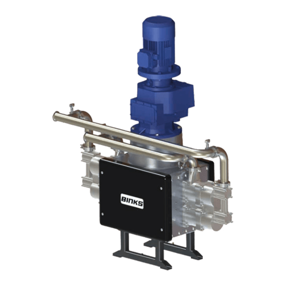
E4-100
Electric Drive Pump
• 104231-XXX (USA Model)
IMPORTANT! DO NOT DESTROY
It is the Customer's responsibility to have all operators and service personnel read and understand this
manual.
Contact your local Carlisle Fluid Technologies representative for additional copies of this manual.
READ ALL INSTRUCTIONS BEFORE OPERATING THIS PRODUCT
77-3330 R1.3
1/36
www.carlisleft.com
Advertisement
Table of Contents

Related Manuals for Carlisle BINKS E4-100


Summary of Contents for Carlisle BINKS E4-100
- Page 1 IMPORTANT! DO NOT DESTROY It is the Customer's responsibility to have all operators and service personnel read and understand this manual. Contact your local Carlisle Fluid Technologies representative for additional copies of this manual. READ ALL INSTRUCTIONS BEFORE OPERATING THIS PRODUCT 77-3330 R1.3 1/36 www.carlisleft.com...
-
Page 2: Eu Declaration Of Conformity
Providing all conditions of safe use / installation stated within the product manuals have been complied with and also installed in accordance with any applicable local codes of practice. Director of Sales (EMEA) D Smith Signed for and on behalf of Carlisle Fluid Technologies UK Ltd: 29/6/18 Bournemouth,BH11 9LH,UK 77-3330 R1.3... - Page 3 In this part sheet, the words WARNING, CAUTION and NOTE are used to emphasize important safety information as follows: WARNING CAUTION NOTE Hazards or unsafe practices which could result in Hazards or unsafe practices which could result in Important installation, operation or maintenance severe personal injury, death or substantial property minor personal injury, product or property information.
-
Page 4: Specification
Specification Nominal pump stroke: 60mm [2.36 ins] * E4-100 Maximum fluid pressure: 20bar [290psi] E4-100 Nominal Flow Volume / Cycle: 2.5 l/m [0.65 US gal/m] Fluid Output @ 20 HZ [10 cycles/min] 25 l/m [6.5 US gal/m] Fluid Output @ 80 HZ [40 cycles/min] 100 l/m [26 US gal/m] 'A' Fluid inlet connection: 2'' NOTE... -
Page 5: Dimensions And Mounting Details
DIMENSIONS AND MOUNTING DETAILS M6 Hex Head screw for pump earth grounding The Pump Frame must be wired to a suitable earth ground to ensure that there is no possibility of static build up. 77-3330 R1.3 5/36 www.carlisleft.com... -
Page 6: Installation
INSTALLATION The Pump Units are designed for location in Zone 1 Hazardous areas, ATEX Category 2.(Motor Gearbox Dependant) Electrical connections must be in accordance with Local Regulations for installation in Hazardous Areas. It is recommended that a Local Control Box is positioned in close proximity to the pump, as a convenient local Start / Stop facility and Junction box. -
Page 7: Electric Motor
INSTALLATION Electric Motor The motor must be wired to provide a clockwise direction of the cam. Electric Motors for hazardous areas are specially designed to comply with official regulations concerning the risk of explosion. If improperly used, badly connected, or altered no matter how minor, their reliability could be in doubt. Standards relating to the connection and use of electrical apparatus in hazardous areas must be taken into consideration. - Page 8 INSTALLATION • Attach suitable flexible hoses to the inlet and outlet connections. E.g. - Ø50 I.D. [-1 to 10 bar working pressure] • Suction - Ø38 - 50 I.D. [20 bar working pressure] • Outlet Ensure adequate air space around the Pump for maintenance and electric motor cooling requirements. •...
-
Page 9: System Operation
SYSTEM OPERATION Before starting:- • Ensure all electrical and mechanical connections are correctly made. • All required interlocks are tested and operational. • Suitable material for pumping is available at the suction hose. • The outlet connection is not blocked or isolated by any valves. •... - Page 10 104231 Pump Assembly - PARTS LIST ITEM PART NO. DESCRIPTION REMARKS 193116 3.7KW (5HP) ELECTRIC MOTOR USA MODEL 192687 GEARBOX USA MODEL 195652 FLUID SECTION 195670 MANIFOLD & PRV ASSEMBLY 195673 COVER C/W CAP FIXINGS 195679 E4-100 MECHANICAL ASSY 77-3330 R1.3 10/36 www.carlisleft.com...
- Page 11 GREASE LOCTITE TORQUE MAINTENANCE ORDER (Reverse for assembly) GREASE INTERNAL (AGMD-010) 77-3330 R1.3 11/36 www.carlisleft.com...
- Page 12 195670 PRV and Manifold Assembly - PARTS LIST ITEM PART NO. DESCRIPTION REMARKS Service Manual 104253-E4 PRV ASSEMBLY - 22 BAR 77-3243 192029 2'' SANITARY GASKET 192544 2'' SANITARY CLAMP 2" STANDARD 90° ELBOW 192791 88.9mm (EQUAL) 2" EXTENDED 90° ELBOW 194930 102.1mm (UNEQUAL) 194931...
- Page 13 195679 Mechanical Assembly - PARTS LIST ITEM PART NO. DESCRIPTION REMARKS 164470 M12 PLAIN WASHER 165044 M12 SPRING WASHER 165097 M16 PLAIN WASHER 165100 M16 SPRING WASHER 165108 M8 SPRING WASHER 165123 M10 SPRING WASHER 165134 M8 PLAIN WASHER 165139 M20 SPRING WASHER 165349 M12 X 40 HEX HEAD SCREW...
- Page 14 GREASE LOCTITE TORQUE MAINTENANCE ORDER (Reverse for assembly) GREASE INTERNAL (AGMD-010) ** Tighten bolts holding carriage ends once pump is fully assembled - see note on carriage assembly drawing 77-3330 R1.3 14/36 www.carlisleft.com...
- Page 15 165661 PARTS LIST - Shaft Assembly ITEM PART NO. REMARKS DESCRIPTION M10 X 100 CAP HEAD SCREW 177134 (PLATED) 195645 E4-100 CONSTANT VELOCITY CAM 195657 TOP SHAFT 195658 MIDDLE SHAFT 195659 BASE SHAFT 77-3330 R1.3 15/36 www.carlisleft.com...
- Page 16 CAM radial pitch offset Assembly tool 1. Hold assembly tool (502512) in a vice (flats provided) and install middle shaft. 2. Place CAM onto middle shaft ( with 'Top' engraving facing down). 3. Place the base shaft on top of the CAM, align the holes and screw in the M10 x 100 cap head screws using Loctite 243 and cross-tighten evenly to 65Nm.
- Page 17 165660 PARTS LIST - BELL HOUSING CAM ASSY ITEM PART NO. DESCRIPTION REMARKS 163951 M6 X 16 CAP HD SCREW (ST ST) 163952 M6 X 20 20 CAP HD SCREW (ST ST) 192616 BEARING CAP 192640 Ø45 X Ø100 X 36 ROLLER BEARING ...
- Page 18 165669 PARTS LIST - Carriage Assembly ITEM PART NUMBER DESCRIPTION REMARKS 162885 Ø61 x 2.0 O-RING 165108 M8 SPRING WASHER 165968 M5 x 8 GRUBSCREW 166158 CIRCLIP 177012 M10 x 25 CAP HD SCREW 177056 M8 x 16 HEX HD SCREW 177094 M16 x 30 C'SUNK SCREW 192139...
- Page 19 (ITEM 8) Tighten on final (ITEM 19) When fitting new bearings: assembly to give correct Ensure seals have been removed from inside of orientation for hose connection bearing to ensure a correct grease supply path via to grease nipple. centre spacer. (ITEM 19) Orientate bearing so black section along the body is aligned to the block's side. GREASE LOCTITE TORQUE MAINTENANCE ORDER (Reverse for assembly) GREASE INTERNAL (AGMD-010) 77-3330 R1.3 19/36 www.carlisleft.com...
- Page 20 Carriage Installation When installing carriages into mechanical section ensure upper and lower carriages are inverted. This is to ensure adequate room surrounding grease elbows. See above images as reference. To remove carriage for maintenance, remove linear rods (193449) from mechanical section.
- Page 21 165678 PARTS LIST - CARRIAGE SPRING ROD ASSY ITEM PART NO. DESCRIPTION REMARKS 163161 AERONUT 165552 SOCKET HEAD CAP SCREW 192400 SPRING WASHER 193101 SPRING KEEP 193103 ROD BEARING 193434 SPRING 195677 CARRIAGE SPRING ROD GREASE LOCTITE TORQUE MAINTENANCE ORDER (Reverse for assembly) GREASE INTERNAL (AGMD-010)
- Page 22 195652 PARTS LIST - Fluid Section ITEM PART NO. DESCRIPTION REMARKS 160513 CONICAL SPRING 164472 M8 x 25 CAP HD SCREW (ST ST) 165077 M14 SPRING WASHER 165108 M8 SPRING WASHER (ST ST) 165957 M8 x 90 CAP HD SCREW (ST ST) 171788 ...
- Page 23 GREASE LOCTITE TORQUE MAINTENANCE ORDER (Reverse for assembly) GREASE INTERNAL (AGMD-010) 77-3330 R1.3 23/36 www.carlisleft.com...
- Page 24 194244 PARTS LIST - Piston Assembly ITEM PART NO. DESCRIPTION REMARKS 160513 CONICAL SPRING 162805 Ø63.17 x Ø2.62 O-RING 162807 Ø50.52 x Ø1.78 O-RING 162854 Ø82.22 x Ø2.62 O-RING 171784 1.75 ST ST BALL 192629 INLET SPRING KEEP ...
- Page 25 194177 PARTS LIST - Shaft & Bellows Assembly ITEM PART NO. DESCRIPTION REMARKS 192881 KNIFED BELLOWS 192887 RETAINING NUT 193445 BELLOWS SPACER 193452 PISTON SHAFT 193453 SHAFT SEAL 502682 BELLOWS POSITIONING TOOL (Tool not included) 502681 BELLOWS ASSEMBLY SPIGOT (Tool not included) Screw Item No.
-
Page 26: General Maintenance
Maintenance General Maintenance The working life and thus the expected life prior to replacement of parts within a Paint Pump are greatly affected by three main factors: - Abrasiveness of Fluid Pumped • Pump Duty Cycle • Fluid Pressure Output Requirement •... -
Page 27: Maintenance Schedule
Maintenance Maintenance schedule Inspection Operation Daily Check for any fluid leakage Check for any excessive mechanical noise Check for excessive fluid pressure pulsation Weekly Check oil level within gearbox Grease Cam Follower Bearings (8 off) with 502375 grease while the pump is 3 Monthly running. - Page 28 Maintenance - Gearbox WARNING Gearbox Every 1000 hours verify the good condition of oil seals and gaskets Maintenance The gearbox is supplied factory fitted with Synthetic Oil. However, if seals start to leak and oil level is reduced, both the affected seal and oil need to be replaced as a general overhaul of the unit.
-
Page 29: Electric Motors
Maintenance - Motor WARNING Wait until the unit has cooled sufficiently after stopping and isolation. Electric Motors Maintenance of Ex Motors - are reported by EN 60079-17 standard, in particular:- • The electric connections must be correctly locked to avoid resistance-increases, with consequent contact overheating. -
Page 30: Fault Finding
Fault finding Mechanical Symptom Possible Cause Remedy Gearbox Output shaft does not Drive between shafts in the gear unit Return the unit for repair and replace rotate, even though the motor is interrupted gearbox running. Gearbox Oil leaking a) Defective gasket on gear unit a) Retighten screws on gear unit •... -
Page 31: Fluid Section
Fault finding Fluid Section Symptom Possible Cause Remedy a) Air entering the suction a) Check o-rings and hose hose/manifold connections b) Worn piston seals b) Replace piston seals. Pump will not ‘Prime’ c) Ball checks not seating correctly. c) Inspect, clean/replace balls/seats a) No power a) Check electrical supply Pump will not run... - Page 32 Testing and Lubricating Testing and Lubricating after major overhaul WARNING Testing and Lubricating - Qualified personnel only 1. Connect pump to paint system. 2. Connect electric motor to a suitable electrical supply. 3. Fit the gearbox vent plug. 4. Turn on paint system and set back pressure regulator to zero. 5.
-
Page 33: Spare Parts List
Spare Parts List Recommended Replacement Spare Parts and Kits for E4-60 Pumps Kit No. Part No. Description Remarks 195645 Constant Velocity Cam 2 off per pump 194244 Ø114 Piston 4 off per pump 193278 Glass Filled PTFE Fluid Piston Seal 4 off per pump 192688 Auto Lubrication Kit... - Page 34 Accessories Part No. Description Remarks 192800 Smart Card 502373 Grease Gun for Cam Follower (& Main Bearings) Collet Connector 502514 Grease Gun For Linear Bearings (300mm Extension) Hook Connector 502375 Grease Gun for Cam Follower (& Main Bearings) 502376 Grease for Linear Bearings 502501 Back Pressure Regulator Box 192569...
- Page 35 ACCESSORIES PART NUMBER DESCRIPTION REMARKS 192450 M8 Torx Security Screwdriver for Cover FOC with a New Pump 502891 Top Bearing Locknut Tool 502509 Bottom Bearing Locknut Tool 502928 Top Bearing Press Tool 502511 Bottom Bearing Press Tool 502512 Shaft Assembly Tool 502681 Bellows Assembly Tool 502682...
-
Page 36: Warranty Policy
WARRANTY POLICY This product is covered by Carlisle Fluid Technologies’ materials and workmanship limited warranty. The use of any parts or accessories, from a source other than Carlisle Fluid Technologies, will void all warranties. Failure to reasonably follow any maintenance guidance provided, may invalidate any warranty.
Need help?
Do you have a question about the BINKS E4-100 and is the answer not in the manual?
Questions and answers