SCHUNK PZN-plus Assembly And Operating Manual
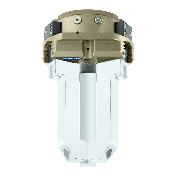
3-finger centric gripper
Hide thumbs
Also See for PZN-plus:
- Assembly and operating manual (43 pages) ,
- Assembly and operating manual (56 pages)

Related Manuals for SCHUNK PZN-plus


Summary of Contents for SCHUNK PZN-plus
- Page 1 Assembly and Operating Manual PZN-plus 3-Finger Centric Gripper Translation of the original manual...
-
Page 2: Table Of Contents
4 Design and description ................19 4.1 Design ....................19 4.2 Description ..................19 5 Assembly.................... 20 5.1 Installing and connecting ..............20 5.2 Connections ..................21 5.2.1 Mechanical connection..............21 210.00 | PZN-plus | Assembly and Operating Manual | en | 389374... - Page 3 7.4.5 Version with force amplification cylinder (KVZ)........59 7.4.6 Notes for assembly ..............61 7.4.7 Screw tightening torques ............. 61 7.4.8 Spring force information for assembly ..........61 210.00 | PZN-plus | Assembly and Operating Manual | en | 389374...
- Page 4 7.5.2 Variant with dust cover ............... 64 7.5.3 Variant with force amplification cylinder ......... 65 8 Translation of the original declaration of incorporation ......... 66 9 UKCA declaration of incorporation ............67 210.00 | PZN-plus | Assembly and Operating Manual | en | 389374...
-
Page 5: General
Dangers for persons! Non-observance can lead to irreversible injury and even death. CAUTION Dangers for persons! Non-observance can cause minor injuries. CAUTION Material damage! Information about avoiding material damage. 210.00 | PZN-plus | Assembly and Operating Manual | en | 389374... -
Page 6: Definition Of Terms
PZN-plus with gripping force maintenance O.D. gripping PZN-plus with gripping force maintenance I.D. gripping PZN-plus Anti-corrosion version PZN-plus high-temperature (V/HT) PZN-plus Force intensified version (KVZ) PZN-plus Dust-tight PZN-plus Precision version PZN-plus ATEX (EX) 210.00 | PZN-plus | Assembly and Operating Manual | en | 389374... -
Page 7: Warranty
2 x Cylindrical pin ID.-No. of the accessory pack: Size ID number 5521694 5520796 5512728 5512729 5512730 5512731 5512732 5512733 5514005 5514240 5520730 high-temperature (V/HT) 5521695 5520797 395512728 395512729 210.00 | PZN-plus | Assembly and Operating Manual | en | 389374... -
Page 8: Accessories
[/ 62]. Size ID number 5516815 5516816 0303450 0303451 0303452 0303453 0303454 0303455 0303456 0303457 0303458 high-temperature (V/HT) 395516815 395516816 39303450 39303451 39303452 39303453 39303454 39303455 39303456 210.00 | PZN-plus | Assembly and Operating Manual | en | 389374... - Page 9 39303458 Dust-tight 5518720 5518721 5518722 5518723 5518724 5518725 5518726 5518727 5518728 5518729 5522513 Force intensified version (KVZ) 5515869 5515870 5515871 5515872 5515873 Tab.: ID.-No. of the accessory pack 210.00 | PZN-plus | Assembly and Operating Manual | en | 389374...
-
Page 10: Basic Safety Notes
Use only original spare parts or spares authorized by SCHUNK. 2.4 Gripper fingers Requirements of gripper fingers Accumulated energy can make the product unsafe and risk the danger of serious injuries and considerable material damage. 210.00 | PZN-plus | Assembly and Operating Manual | en | 389374... -
Page 11: Ambient Conditions And Operating Conditions
Instructed person Instructed persons were instructed by the operator about the delegated tasks and possible dangers due to improper behaviour. 210.00 | PZN-plus | Assembly and Operating Manual | en | 389374... -
Page 12: Personal Protective Equipment
Eliminate any malfunction immediately. Observe the care and maintenance instructions. Observe the current safety, accident prevention and environmental protection regulations regarding the product's application field. 210.00 | PZN-plus | Assembly and Operating Manual | en | 389374... -
Page 13: Transport
Disconnect power sources before installation, modification, maintenance, or calibration. Ensure that no residual energy remains in the system. If the energy supply is connected, do not move any parts by hand. 210.00 | PZN-plus | Assembly and Operating Manual | en | 389374... -
Page 14: Protection During Handling And Assembly
Perform maintenance work, modifications, and attachments outside the danger zone defined by the movement range. 210.00 | PZN-plus | Assembly and Operating Manual | en | 389374... -
Page 15: Protection Against Electric Shock
The effectiveness of the potential equalisation must be verified by executing regular safety measurements. 210.00 | PZN-plus | Assembly and Operating Manual | en | 389374... -
Page 16: Notes On Particular Risks
Before starting any work on the product: Switch off the power supply and secure against restarting. Make sure, that no residual energy remains in the system. 210.00 | PZN-plus | Assembly and Operating Manual | en | 389374... - Page 17 Secure the end positions of the product with SCHUNK SDV-P pressure maintenance valves. 210.00 | PZN-plus | Assembly and Operating Manual | en | 389374...
-
Page 18: Technical Data
SCHUNK also offers customized solutions for special applications in dirty ambient conditions. More technical data is included in the catalog data sheet. Whichever is the latest version. 210.00 | PZN-plus | Assembly and Operating Manual | en | 389374... -
Page 19: Design And Description
3-Finger Centric Gripper Housing Base jaw Compressed air main connection 4.2 Description Universal 3-finger centric gripper with high gripping force and high maximum moments due to multi-tooth guidance. 210.00 | PZN-plus | Assembly and Operating Manual | en | 389374... -
Page 20: Assembly
ð Screw in air connections (plug connections). OR: Screw on throttle valve in order to be able to perform sufficient throttling and/or damping. Screw the product to the machine/system, [/ 21]. } 5.2.1 210.00 | PZN-plus | Assembly and Operating Manual | en | 389374... -
Page 21: Connections
① Centering sleeve ② Screws * Ø4 M2.5 / 6 Ø5 M3 / 8 Ø6 M4 / 10 Ø8 M5 / 10 Ø10 M6 / 13 Ø10 M6 / 13 210.00 | PZN-plus | Assembly and Operating Manual | en | 389374... - Page 22 The recess/bore in the adapter plate may not exceed the dimension "A"; for dimensions, see the following table. Size Max. recess "A" [mm] Ø24 Ø32 Ø40 Ø55 Ø70 Ø85 Ø115 Ø150 Ø196 Ø236 Ø292 210.00 | PZN-plus | Assembly and Operating Manual | en | 389374...
- Page 23 M10 / 51.5 Ø6 M12 / 25 Ø8 200 (AS / IS) M12 / 61 Ø8 Ø8 Ø10 Ø12 * Thread / max. depth of engagement from locating surface [mm] 210.00 | PZN-plus | Assembly and Operating Manual | en | 389374...
-
Page 24: Pneumatic Connection
Product variants are also offered with mechanical gripping force via springs, which also ensure a minimum clamping force in the event of a pressure drop. Air connections 210.00 | PZN-plus | Assembly and Operating Manual | en | 389374... - Page 25 Hose-free direct connection Product O-ring Attachment Size Main air Hose-free direct Air purge connections connection connection G1/8" G1/8" G1/8" G1/8" G1/4" G1/4" G1/4" Tab.: Thread diameter of the air connections 210.00 | PZN-plus | Assembly and Operating Manual | en | 389374...
-
Page 26: Mounting The Sensor
Information on handling sensors is available at schunk.com or from SCHUNK contact persons. 5.3.1 Overview of sensors 210.00 | PZN-plus | Assembly and Operating Manual | en | 389374... -
Page 27: Setting Dimensions For Magnetic Switches
38.0 64-KVZ 45.5 64 AS-KVZ 59.0 64 IS-KVZ 59.0 26.9 80 AS 42.3 80 IS 42.3 80-KVZ 51.9 80 AS-KVZ 66.9 80 IS-KVZ 66.9 29.8 100 AS 49.9 210.00 | PZN-plus | Assembly and Operating Manual | en | 389374... -
Page 28: Switch-Off Hysteresis For Magnetic Switches
X ≤ 5 mm 30 % of the nominal stroke per jaw X > 5 mm to X ≤ 10 mm 20 % of the nominal stroke per jaw 210.00 | PZN-plus | Assembly and Operating Manual | en | 389374... -
Page 29: Turn Control Cam
Undo the screw (2). Remove control cam (1) from the product, turn and re-insert it into the product. Turn the screw (3) to push the position of the control cam (1). 210.00 | PZN-plus | Assembly and Operating Manual | en | 389374... -
Page 30: Mounting Inductive Proximity Switch In 80
Tighten the screw (3) on the bracket (2). Tightening torque: 0.2 Nm Open gripper or grip part. Undo the screw (4). Turn the screw (5) to push the position of the control cam (6). 210.00 | PZN-plus | Assembly and Operating Manual | en | 389374... - Page 31 If the switching position cannot be queried, it may be that the alignment of the control cam has to be changed, [/ 29]. } 5.3.4 Variant Dust-tight: Screw in set-screw into the side cover. 210.00 | PZN-plus | Assembly and Operating Manual | en | 389374...
-
Page 32: Mounting Magnetic Switch Mms 22
(3), until the sensor 2 (1) switches. Secure the sensor 2 (1) using the set-screw (4). Tightening torque: 10 Ncm Bring product into the "Gripper closed" or "Part gripped" position and test the function. 210.00 | PZN-plus | Assembly and Operating Manual | en | 389374... -
Page 33: Mounting Programmable Magnetic Switch Mms 22-Pi2
OR: Slide the sensor (1) into the groove (2) until the sensor (1) stops at the T-nut (3). Secure the sensor (1) using the set-screw (4). Tightening torque: 10 Ncm Adjust sensor (1), see sensor assembly and operating manual. 210.00 | PZN-plus | Assembly and Operating Manual | en | 389374... -
Page 34: Mounting Programmable Magnetic Switch Mms-P 22
OR: Slide the sensor (1) into the groove (2) until the sensor (1) stops at the T-nut (3). Secure the sensor (1) using the set-screw (4). Tightening torque: 10 Ncm Adjust sensor (1), see sensor assembly and operating manual. 210.00 | PZN-plus | Assembly and Operating Manual | en | 389374... -
Page 35: Mounting Programmable Magnetic Switch Mms 22-Pi1
Secure the sensor 1 (1) using the set-screw (3). Tightening torque: 10 Ncm Hold teaching tool to the sensor 1 (1) to confirm the position. ð The sensor 1 (1) has been taught in. Repeat steps for sensor 2. 210.00 | PZN-plus | Assembly and Operating Manual | en | 389374... - Page 36 Adjust sensor 1 (1), see sensor assembly and operating manual. Repeat steps for sensor 2. NOTE If there is no T-nut available, slide the sensor according to dimension I1 into the groove (2), } 5.3.2 [/ 27]. 210.00 | PZN-plus | Assembly and Operating Manual | en | 389374...
-
Page 37: Mounting The Magnetic Switch Mms 22-Iol
64-1-KVZ 45.5 64-1-AS-KVZ / 64-1-IS-KVZ 59.0 80-1 29.8 80-1-AS / 80-1-IS 29.8 80-1-KVZ 54.8 80-1-AS-KVZ / 80-1-IS-KVZ 70.8 100-1 29.8 100-1-AS / 100-1-IS 49.9 100-1-KVZ 59.8 100-1-AS-KVZ / 100-1-IS-KVZ 79.9 125-1 35.0 125-1-AS / 125-1-IS 58.5 125-1-KVZ 70.0 125-1-AS-KVZ / 125-1-IS-KVZ 93.5 210.00 | PZN-plus | Assembly and Operating Manual | en | 389374... - Page 38 SCHUNK. Size Stroke 1 Stroke 2 100 % 15 % 100 % 15 % PZN-plus 8 mm 1.2 mm 4 mm 0.6 mm 80-AS 210.00 | PZN-plus | Assembly and Operating Manual | en | 389374...
- Page 39 OR: Slide the sensor (1) into the groove (2) until the sensor (1) stops at the T-nut (3). Secure the sensor (1) using the set-screw (4). Tightening torque: 10 Ncm 210.00 | PZN-plus | Assembly and Operating Manual | en | 389374...
-
Page 40: Mounting The Analog Position Sensor Aps-Z80
Analog signal on I.D. gripping Variant Dust-tight: Before attaching the sensor, remove the sealing bolts from the bracket. Before adjusting the control cam, unscrew the set-screw from the side cover. 210.00 | PZN-plus | Assembly and Operating Manual | en | 389374... - Page 41 Tighten the screw (3) on the bracket (2). Tightening torque: 0.2 Nm Adjust sensor (1), see the Sensor Assembly and Operating Manual. Variant Dust-tight: Screw in set-screw into the side cover. 210.00 | PZN-plus | Assembly and Operating Manual | en | 389374...
-
Page 42: Mounting Reed Switch Rms 22
(3), until the sensor 2 (1) switches. Secure the sensor 2 (1) using the set-screw (4). Tightening torque: 10 Ncm Bring product into the "Gripper closed" or "Part gripped" position and test the function. 210.00 | PZN-plus | Assembly and Operating Manual | en | 389374... -
Page 43: Mounting The Reed Switch Rms 80
Tighten the screw (3) on the bracket (2). Tightening torque: 0.2 Nm Open gripper or grip part. Undo the screw (4). Turn the screw (5) to push the position of the control cam (6). 210.00 | PZN-plus | Assembly and Operating Manual | en | 389374... - Page 44 If the switching position cannot be queried, it may be that the alignment of the control cam has to be changed, [/ 29]. } 5.3.4 Variant Dust-tight: Screw in set-screw into the side cover. 210.00 | PZN-plus | Assembly and Operating Manual | en | 389374...
-
Page 45: Mounting Flexible Position Sensor Fps
Tighten the screw (3) on the bracket (2). Tightening torque: 0.2 Nm Adjust sensor (1), see assembly and operating manual of the sensor. Variant Dust-tight: Screw in set-screw into the side cover. 210.00 | PZN-plus | Assembly and Operating Manual | en | 389374... -
Page 46: Mounting The Analog Position Sensor Aps-M1
Slide control cam (6) out of the mounting kit front into the base jaw. ð Ensure that the higher front side of the control cam (6) is pointing outwards. 210.00 | PZN-plus | Assembly and Operating Manual | en | 389374... -
Page 47: Mounting The Radio System Rss-R1/T2
[/ 43]. } 5.3.13 Adjust the sensor, see the assembly and operating manual for the sensor. Connect the radio system, see the assembly and operating manual for the radio system. 210.00 | PZN-plus | Assembly and Operating Manual | en | 389374... -
Page 48: Troubleshooting
One-way flow control valve is missing or Install and adjust one-way flow control valve. adjustet incorrectly. Loading too large. Check permissible weight and length of the gripper fingers. 210.00 | PZN-plus | Assembly and Operating Manual | en | 389374... -
Page 49: Gripping Force Is Dropping
6.6 Programmable magnetic switches not switching as desired Possible cause Corrective action Incorrect position of sensor Check adjustment dimensions, [/ 27]. } 5.3.2 Magnetic field too weak Check function of sensor in both grooves. 210.00 | PZN-plus | Assembly and Operating Manual | en | 389374... -
Page 50: Maintenance
O.D. gripping The pistons have to be aligned using an assembly device. Therefore we recommend to have the module serviced and the seals replaced by SCHUNK. 210.00 | PZN-plus | Assembly and Operating Manual | en | 389374... -
Page 51: Maintenance Intervals
[/ 53]. } 7.4 The seals are in the enclosed sealing kit., [/ 8]. } 1.4.1 Treat all grease areas with lubricant, [/ 52]. } 7.3 Oil or grease external steel parts. 210.00 | PZN-plus | Assembly and Operating Manual | en | 389374... -
Page 52: Lubricants/Greasing Areas (Basic Lubrication)
All other lubrication points like seal and hole at the piston must be relubricated every 1 million cycles. Therefore the gripper must be disassembled. 210.00 | PZN-plus | Assembly and Operating Manual | en | 389374... -
Page 53: Disassembly And Assembly
(60) from the housing (1). Push the piston (3 / 8) upwards and out of the housing (1). Pull the base jaw (2 / 7) out of the housing (1). 210.00 | PZN-plus | Assembly and Operating Manual | en | 389374... -
Page 54: Version With Gripping Force Maintenance O.d
Before starting any work on the product: Switch off the power supply and secure against restarting. Make sure, that no residual energy remains in the system. 210.00 | PZN-plus | Assembly and Operating Manual | en | 389374... - Page 55 (2) and the cover (9) in a press (100), so that the 8 screws (46) still can be removed. Unscrew the screws (46). Open press (100) carefully. Remove the cover (5). Remove centering pins (55). 210.00 | PZN-plus | Assembly and Operating Manual | en | 389374...
- Page 56 Remove the cylinder piston (60) and the compression springs (25) from the housing (1). Push the piston (3) upwards and out of the housing (1). Pull the base jaws (2) out of the housing (1). 210.00 | PZN-plus | Assembly and Operating Manual | en | 389374...
-
Page 57: Version With Gripping Force Maintenance I.d
Before starting any work on the product: Switch off the power supply and secure against restarting. Make sure, that no residual energy remains in the system. 210.00 | PZN-plus | Assembly and Operating Manual | en | 389374... - Page 58 Remove the cylinder piston (60) out of the housing (1). Push the pistons (3) upwards out of the housing (1). Pull the base jaws (2) out of the housing (1). 210.00 | PZN-plus | Assembly and Operating Manual | en | 389374...
-
Page 59: Version With Force Amplification Cylinder (Kvz)
Risk of injury due to spring forces! The spring-loaded pressure piece is under spring tension and may jump out when being removed. Carefully unfasten the set screw and slowly remove the spring-loaded pressure piece. 210.00 | PZN-plus | Assembly and Operating Manual | en | 389374... - Page 60 (60) and the housing (1). Remove the cylinder piston (60) from the housing (1). Push the piston (3) upwards out of the housing (1). Pull the base jaws (2) out of the housing (1). 210.00 | PZN-plus | Assembly and Operating Manual | en | 389374...
-
Page 61: Notes For Assembly
Tab.: Tightening torque [Nm] 7.4.8 Spring force information for assembly with gripping force Size Pre-tension distance Spring force [N] maintenance O.D. [mm] gripping 1253 2372 4982 5016 9465 10130 210.00 | PZN-plus | Assembly and Operating Manual | en | 389374... -
Page 62: Drawings
13464 14163 7.5 Drawings The following figures are example images. They serve for illustration and assignment of the spare parts. Variations are possible depending on size and variant. 210.00 | PZN-plus | Assembly and Operating Manual | en | 389374... -
Page 63: Basic Module
Positions are adapted to each other and can not be replaced by the customer. not for PZN-plus 40 - 125 size PZN-plus 160 -300 from size PZN-plus 125 at size PZN-plus 380 210.00 | PZN-plus | Assembly and Operating Manual | en | 389374... -
Page 64: Variant With Dust Cover
Maintenance 7.5.2 Variant with dust cover 210.00 | PZN-plus | Assembly and Operating Manual | en | 389374... -
Page 65: Variant With Force Amplification Cylinder
Wearing part, replace during maintenance. Included in the seal kit. Seal kit can only be ordered completely. not for PZN-plus 64 - 125 from size PZN-plus 125 from size PZN-plus 160 210.00 | PZN-plus | Assembly and Operating Manual | en | 389374... -
Page 66: Translation Of The Original Declaration Of Incorporation
Person authorized to compile the technical documentation: Stefanie Walter, Address: see manufacturer's address Lauffen/Neckar, March 2024 Dr.-Ing. Manuel Baumeister, Head of Systems Engineering, Technology & Innovation 210.00 | PZN-plus | Assembly and Operating Manual | en | 389374... -
Page 67: Ukca Declaration Of Incorporation
Person authorized to compile the technical documentation: Marcel Machado, address: refer to manufacturer's address Lauffen/Neckar, March 2024 Dr.-Ing. Manuel Baumeister, Head of Systems Engineering, Technology & Innovation 210.00 | PZN-plus | Assembly and Operating Manual | en | 389374... - Page 68 Folgen Sie uns I Follow us Wir drucken nachhaltig I We print sustainable...
Need help?
Do you have a question about the PZN-plus and is the answer not in the manual?
Questions and answers