
Subscribe to Our Youtube Channel
Related Manuals for SCHUNK ROTA NC plus 2 Series


Summary of Contents for SCHUNK ROTA NC plus 2 Series
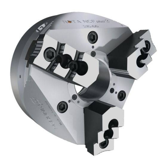
- Page 1 Translation from the original operating manual Power chuck ROTA NC plus 2 / ROTA NCF plus 2 Assembly and Operating Manual Superior Clamping and Gripping...
- Page 2 Imprint Copyright: This manual is protected by copyright. The author is SCHUNK GmbH & Co. KG. All rights reserved. Any reproduction, processing, distribution (making available to third parties), translation or other usage - even excerpts - of the manual is especially prohibited and requires our written approval.
-
Page 3: Table Of Contents
Table of contents Table of contents 1 General ........................5 1.1 Warnings ........................5 1.2 Applicable documents ....................6 2 Basic safety instructions ................... 7 2.1 Intended use ......................7 2.2 Not intended use ...................... 7 2.3 Notes on particular risks ................... 8 2.4 Notes on safe operation .................. - Page 4 Table of contents 8.3 Disassembly and assembly of the Chuck ..............36 9 Maintenance ......................38 9.1 Lubrication ......................38 9.2 Maintenance intervals .................... 39 9.3 Changing the top jaws .................... 39 10 Disposal ........................40 11 Spare parts ......................40 12 Drawing........................
-
Page 5: General
General General This operating manual is an integral component of the product and contains important information on safe and proper assembly, commissioning, operation, care, maintenance and disposal. This manual must be stored in the immediate vicinity of the product where it is accessible to all users at all times. Before using the product, read and comply with this manual, especially the chapter “Basic safety notes”.(... -
Page 6: Applicable Documents
Applicable documents • * • * • , "Technology" chapter in the lathe chuck catalog * The documents marked with an asterisk (*) can be downloaded on our homepage schunk.com 02.00|ROTA NC plus 2 / ROTA NCF plus 2 |en... -
Page 7: Basic Safety Instructions
Only original SCHUNK spare parts may be used. Intended use The chuck is used to clamp workpieces on machine tools and other suitable technical facilities, paying particular attention to the technical data specified by the manufacturer. -
Page 8: Notes On Particular Risks
Basic safety instructions Notes on particular risks DANGER Risk of fatal injury to operating personnel due to the workpiece falling down or being flung out in the event of a power failure In the event of a power failure, the lathe chuck's clamping force may fail immediately and the workpiece may be released in an uncontrolled manner. - Page 9 Basic safety instructions DANGER Possible risk of fatal injury to operating personnel from clothing or hair being caught on the lathe chuck and being dragged into the machine Loose clothing or long hair may become caught on projecting parts of the lathe chuck and be drawn into the machine. •...
- Page 10 Basic safety instructions CAUTION Danger of limbs being crushed by opening and closing of the chuck jaws during manual loading and unloading or when replacing moving parts. • Do not reach between the jaws. • Wear safety gloves. • Observe the safety and accident prevention regulations during operation of the chuck, especially in connection with machining centers and other technical equipment.
-
Page 11: Notes On Safe Operation
Basic safety instructions Notes on safe operation • The machine spindle may only be started up when clamping pressure has built up in the cylinder and clamping has followed in the permitted work area. • Unclamping may only be possible when the machine spindle has come to a standstill. - Page 12 (clamping force, coefficient of friction, wear characteristics). (For product information about LINOMAX, see the "Accessories" chapter of the SCHUNK lathe chuck catalog or contact SCHUNK). • Use a suitable high-pressure grease gun to ensure that you reach all the greasing areas.
- Page 13 • If the chuck is involved in a collision, it must be subjected to a crack test before using it again. Replace damaged parts with original SCHUNK spare parts. • Replace the chuck jaw mounting screws if there are signs of wear or damage.
-
Page 14: Substantial Modifications
Only allow specialists to remedy faults. Spare parts Only ever use original SCHUNK spare parts. Environmental regulations Comply with the applicable legal norms when disposing of waste. -
Page 15: Using Personal Protective Equipment
Basic safety instructions Using personal protective equipment When using this product, you must comply with the relevant health and safety at work rules and you must use the required personal safety equipment (minimum: category 2). 02.00|ROTA NC plus 2 / ROTA NCF plus 2 |en... -
Page 16: Warranty
Scope of delivery Warranty If the product is used as intended, the warranty is valid for 24 months from the ex-works delivery date under the following conditions: • Observe the applicable documents, ( 1.2, Page 6) • Observe the ambient conditions and operating conditions •... -
Page 17: Technical Data
Technical data Technical data Chuck data ROTA NC plus 2 ROTA NCF plus 2 Size Max. actuating force [kN] Max. clamping force [kN] Max. speed [rpm] 5000 5000 4000 3500 6000 6000 4500 4000 Stroke per jaw [mm] Piston stroke [mm] Chuck through bore [mm] Weight [kg]... -
Page 18: Clamping Force / Speed Diagrams
The chuck is in perfect condition and lubricated with SCHUNK LINOMAX special grease. If one or more of these prerequisites is modified, the graphs will no longer be valid. - Page 19 Technical data Clamping force RPM graph ROTA NC plus 185-52 Clamping force RPM graph ROTA NC plus 215-66 Clamping force RPM graph ROTA NC plus 260-86 02.00|ROTA NC plus 2 / ROTA NCF plus 2 |en...
- Page 20 Technical data Clamping force RPM graph ROTA NC plus 315-104 Clamping force RPM graph ROTA NC plus 185-52 Clamping force RPM graph ROTA NCF plus 215-66 02.00|ROTA NC plus 2 / ROTA NCF plus 2 |en...
-
Page 21: Calculations For Clamping Force And Speed
Technical data Clamping force RPM graph ROTA NCF plus 260-86 Clamping force RPM graph ROTA NCF plus 315-104 Calculations for clamping force and speed Missing information or specifications can be requested from the manufacturer. Legend Total centrifugal force [N] Centrifugal torque of top jaws [Kgm] Effective clamping force [N] Centrifugal torque of base jaws [Kgm] Minimum required clamping force... -
Page 22: Calculation Of The Required Clamping Force In Case Of A Given Rpm
Technical data 6.3.1 Calculation of the required clamping force in case of a given rpm The initial clamping force F is the total force impacting radially on the workpiece via the jaws due to actuation of the lathe chuck during shutdown. Under the influence of rotation, the jaw mass generates an additional centrifugal force. - Page 23 Technical data The required effective clamping force for machining F calculated from the product of the machining force F and the safety factor S . This factor takes into account uncertainties in the calculation of the machining force. According to VDI 3106: S ≥...
-
Page 24: Calculation Example: Required Initial Clamping Force For A Given Speed
Technical data The centrifugal torque of the base jaws M can be found in the table "Chuck data"( 6.1, Page 17). The centrifugal torque of the top jaws M is calculated as per: 6.3.2 Calculation example: required initial clamping force for a given speed Required initial clamping force F for a given speed n... -
Page 25: Calculation Of The Permissible Speed In Case Of A Given Initial Clamping Force
Technical data Centrifugal torque for one jaw: The chuck has 3 jaws, the total centrifugal torque is: The total centrifugal force can now be calculated: Initial clamping force during shutdown that was sought: 6.3.3 Calculation of the permissible speed in case of a given initial clamping force Calculation of the permissible speed n in case of a given initial... -
Page 26: Grades Of Accuracy
Technical data Identifying the permissible RPM: The calculated RPM n = 1495 is smaller than the maximum permissible RPM of the chuck n = 3200 (see "Chuck data" table ( 6.1, Page 17)). This calculated RPM may be used. Grades of Accuracy The radial and axial runout tolerance correspond to the technical delivery specifications for chucks according to DIN ISO 3442-3. -
Page 27: Attachment And Disassembly Of The Chuck
Attachment and disassembly of the chuck Attachment and disassembly of the chuck The item numbers specified for the corresponding individual components relate to chapter drawings.( 12, Page 42) Pre-assembly measures Carefully lift the product (e.g. using suitable lifting gear) from the packaging. -
Page 28: Inspection Of The Spindle Nose
Attachment and disassembly of the chuck Inspection of the spindle nose Inspection of the spindle nose for mounting the chuck flange Assembly of the chuck To achieve high true running of the chuck, the machine side must be aligned before mounting the flange. For this purpose, check the mounting surfaces on the spindle for radial and axial run-out with a dial indicator (see Fig. -
Page 29: Mounting Of The Chuck
Attachment and disassembly of the chuck Mounting of the chuck 7.3.1 Mounting the chuck with a reduction or extension flange If the chuck is screwed on with an intermediate flange, the following points must be observed: • For mounting the chuck on the machine spindle with a short taper by means of a reduction or extension flange, a corresponding chuck flange is attached on the spindle nose. -
Page 30: Mounting The Chuck By Means Of A Direct Mount
Attachment and disassembly of the chuck Before commissioning the lathe chuck, the eye-bolt has to be removed. • Push the chuck onto the intermediate flange. During this, it must be ensured that the through-holes for attaching the chuck coincide with the threaded holes of the flange (see Fig. "Assembly of the chuck"... -
Page 31: Mounting The Rota Nc Plus / Ncf Plus Chuck With A Centering Edge
Attachment and disassembly of the chuck specified maximum tightening torques (see chapter "Torque per screw" ( 4, Page 16)). Then check again for radial and axial runout (see Fig. "Assembly of the chuck" - E). The obtainable radial and axial runout accuracies depend on the outer diameter of the chuck. - Page 32 Attachment and disassembly of the chuck • Unscrew screw (Item 30) completely from the chuck body (Item NOTE: the same screws (Item 28) can be used to press off the center sleeve (Item 4) from the chuck body through the additional thread.
- Page 33 Attachment and disassembly of the chuck Adapter for extension of the draw tube to the chuck Adapter ROTA O-ring NC plus 2 / NCF plus 2 185-52 M67 x 1.5 15.0 66 x 2 NC plus / NCF plus 315-104 M74 x 1.5 15.0 72 x 2...
-
Page 34: Function And Handling
Function and handling Function and handling The item numbers specified for the corresponding individual components relate to chapter drawings.( 12, Page 42) Function and handling The wedge-hook chuck is actuated by means of a rotating solid or through-hole cylinder. The axial pulling and pushing forces are deflected via the wedge hook angle in the piston and the base jaws to the radial jaw clamping force. - Page 35 Function and handling Tool-free rapid quick change (see Fig. 2): I: Cartridge quick change II: Spring-loaded pressure piece III, IV: Set-screw with soft washer V: Chuck jaws The chuck jaws can be mounted and removed manually without any tools. Position the chuck jaws as in Fig. 1 and then slide into the hook until the chuck jaws noticeably engage.
-
Page 36: Disassembly And Assembly Of The Chuck
Function and handling Rapid quick change with cartridge pin (See Fig. 3): I: Cartridge quick change III, IV: Set-screw with soft washer V: Chuck jaws The chuck jaw (V) can be changed if the pin of the cartridge (I) is depressed with a punch or screwdriver. - Page 37 • Push the base jaws (Item 2) with the seal (Item 39) inward out of the base jaw guide. Degrease and clean all parts and check for damage and wear. Replace damaged parts only with original SCHUNK replacement parts. Prior to assembly, replace all seals and thoroughly grease all parts with LINO MAX special grease.
-
Page 38: Maintenance
If the clamping force has dropped too much or if the base jaws and piston no longer move properly, the chuck has to be disassembled, cleaned, and relubricated. Only use original SCHUNK spare parts when replacing damaged parts. 02.00|ROTA NC plus 2 / ROTA NCF plus 2 |en... -
Page 39: Maintenance Intervals
Maintenance (For product information about LINO MAX, see the "Accessories" chapter of the SCHUNK lathe chuck catalog or contact SCHUNK.) CAUTION Allergic reactions due to grease in contact with skin! Wear gloves. Maintenance intervals Lubrication of the grease areas: Lubrication interval Strain... -
Page 40: Disposal
• Dispose of the chuck's metal parts as scrap metal. Alternatively, you can return the chuck to SCHUNK for proper disposal. Spare parts When ordering spare parts, it is imperative to specify the type, size and above all the manufacturing no of the chuck. - Page 41 Spare parts Item Designation Quantity Compression spring * Compression spring * Steel ball * Seal * Set screw * Set screw *** Compression spring ** Steel ball ** Screws Screws Screws O-ring Conical lubrication nipple O-ring Support ring O-ring O-ring Seal Compression spring * Compression spring *...
-
Page 42: Drawing
Drawing Drawing Only for NCF plus 2 ** Only for chuck sizes 260 - 315 *** Only for NC plus 2 02.00|ROTA NC plus 2 / ROTA NCF plus 2 |en... -
Page 43: Translation Of Original Ec Declaration Of Incorporation
Directive 2006/42/EG, Annex II, Part 1.B of the European Parliament and of the Council on machinery Manufacturer H.-D. SCHUNK GmbH & Co. Spanntechnik KG. Lothringer Str. 23 D-88512 Mengen We hereby declare that on the date of the declaration the following incomplete machine complied with all basic safety and health regulations found in the directive 2006/42/EC of the European Parliament and of the Council on machinery. - Page 44 Appendix on Declaration of Incorporation, as per 2006/42/EC, annex II, No. 1 B Appendix on Declaration of Incorporation, as per 2006/42/EC, annex II, No. 1 B 1. Description of the basic safety and health protection requirements, as per 2006/42/EC, Annex I, that apply to and are fulfilled for the scope of the partly completed machinery: Power Lathe Chucks with Through-hole (centrifugal force Product designation: compensatompensation)
- Page 45 Appendix on Declaration of Incorporation, as per 2006/42/EC, annex II, No. 1 B Required characteristics of guards and protective devices 1.4.1 General requirements 1.4.2 Special requirements for guards 1.4.2.1 Fixed guards 1.4.2.2 Interlocking movable guards 1.4.2.3 Adjustable guards restricting access 1.4.3 Special requirements for protective devices Risks due to other hazards...
Need help?
Do you have a question about the ROTA NC plus 2 Series and is the answer not in the manual?
Questions and answers