SCHUNK PZN-plus 40 Assembly And Operating Manual
3-finger centric gripper
Hide thumbs
Also See for PZN-plus 40:
- Assembly and operating manual (43 pages) ,
- Assembly and operating manual (56 pages) ,
- Assembly and operating manual (68 pages)

Related Manuals for SCHUNK PZN-plus 40


Summary of Contents for SCHUNK PZN-plus 40
- Page 1 Translation of the original manual Assembly and Operating Manual PZN-plus 3-Finger Centric Gripper...
- Page 2 Imprint Copyright: This manual is protected by copyright. The author is SCHUNK GmbH & Co. KG. All rights re- served. Any reproduction, processing, distribution (making available to third parties), translation or other usage - even excerpts - of the manual is especially prohibited and re- quires our written approval.
-
Page 3: Table Of Contents
Table of contents Table of contents General........................ 5 About this manual .................... 5 1.1.1 Presentation of Warning Labels ............... 5 1.1.2 Applicable documents ................ 6 1.1.3 Sizes ...................... 6 1.1.4 Variants..................... 6 Warranty ...................... 7 Scope of delivery .................... 7 1.3.1 Accessories kit .................. 7 Accessories ...................... - Page 4 Table of contents Mounting the sensor .................. 24 5.3.1 Overview of sensors ................ 24 5.3.2 Switch-off hysteresis................ 25 5.3.3 Turn control cam .................. 25 5.3.4 Setting dimensions ................. 26 5.3.5 Mounting MMS 22 magnetic switch............ 27 5.3.6 Mounting MMS 22-PI1 programmable magnetic switch...... 28 5.3.7 Mounting programmable MMS 22-PI2 magnetic switch...... 29 5.3.8 Mounting programmable MMS-P 22 magnetic switch...... 30 5.3.9 Mounting the reed switch RMS 80 ............ 30 5.3.10 Mounting inductive proximity switch IN 80 ........... 32...
-
Page 5: General
General 1 General 1.1 About this manual This manual contains important information for a safe and appro- priate use of the product. This manual is an integral part of the product and must be kept ac- cessible for the personnel at all times. Before starting work, the personnel must have read and under- stood this operating manual. -
Page 6: Applicable Documents
- EX" * The documents marked with an asterisk (*) can be downloaded on our homepage schunk.com 1.1.3 Sizes This operating manual applies to the following sizes: • PZN-plus 40 • PZN-plus 50 • PZN-plus 64 • PZN-plus 80 • PZN-plus 100 •... -
Page 7: Warranty
• 2 x O-ring for hose-free direct connection • 2 x screw plug for hose connection • 2 x Cylindrical pin ID.-No. of the accessory pack Accessory pack for PZN-plus PZN-plus- High-temperature (HT) PZN-plus 40 5521694 5521695 PZN-plus 50 5520796 5520797 PZN-plus 64 5512728 395512728... -
Page 8: Accessories
1.4.1 Sealing kit Seal kit for PZN-plus PZN-plus- PZN-plus- PZN-plus- High- Dust-tight Force temperature intensified (HT) version (KVZ) PZN-plus 40 5516815 395516815 5518720 PZN-plus 50 5516816 395516816 5518721 PZN-plus 64 0303450 39303450 5518722 5515869 PZN-plus 80 0303451... -
Page 9: Basic Safety Notes
Using unauthorized spare parts can endanger personnel and dam- age the product or cause it to malfunction. • Use only original spare parts or spares authorized by SCHUNK. 08.00 | PZN-plus | Assembly and Operating Manual | en | 0389374... -
Page 10: Gripper Fingers
Basic safety notes 2.5 Gripper fingers Requirements for the gripper fingers Stored energy within the product creates the risk of serious injur- ies and significant property damage. • Arrange the gripper fingers in a way that the product reaches either the position "open" or "closed" in a de-energized state. •... -
Page 11: Personal Protective Equipment
Basic safety notes 2.8 Personal protective equipment Use of personal protective equipment Personal protective equipment serves to protect staff against danger which may interfere with their health or safety at work. • When working on and with the product, observe the occupa- tional health and safety regulations and wear the required per- sonal protective equipment. -
Page 12: Transport
Basic safety notes 2.10 Transport Handling during transport Incorrect handling during transport may impair the product's safety and cause serious injuries and considerable material dam- age. • When handling heavy weights, use lifting equipment to lift the product and transport it by appropriate means. •... -
Page 13: Protection During Handling And Assembly
Basic safety notes 2.13.1 Protection during handling and assembly Incorrect handling and assembly Incorrect handling and assembly may impair the product's safety and cause serious injuries and considerable material damage. • Have all work carried out by appropriately qualified personnel. •... -
Page 14: Protection Against Dangerous Movements
Basic safety notes 2.13.3 Protection against dangerous movements Unexpected movements Residual energy in the system may cause serious injuries while working with the product. • Switch off the energy supply, ensure that no residual energy re- mains and secure against inadvertent reactivation. •... -
Page 15: Notes On Particular Risks
Basic safety notes 2.14 Notes on particular risks DANGER Risk of fatal injury from suspended loads! Falling loads can cause serious injuries and even death. Stand clear of suspended loads and do not step within their • swiveling range. Never move loads without supervision. •... - Page 16 Products with a mechanical gripping force maintenance can, dur- ing energy supply failure, still move independently in the direc- tion specified by the mechanical gripping force maintenance. Secure the end positions of the product with SCHUNK SDV-P • pressure maintenance valves.
-
Page 17: Technical Data
* For use in dirty ambient conditions (e.g. sprayed water, vapors, abrasion or processing dust) SCHUNK offers corresponding product options as standard. SCHUNK also offers customized solutions for special applications in dirty ambient conditions. 08.00 | PZN-plus | Assembly and Operating Manual | en | 0389374... -
Page 18: Design And Description
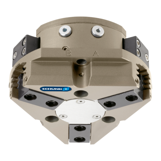
Design and description 4 Design and description 4.1 Design 3-Finger Centric Gripper Housing Base jaw Compressed air main connection 4.2 Description Universal 3-finger centric gripper with high gripping force and high maximum moments due to multi-tooth guidance. 08.00 | PZN-plus | Assembly and Operating Manual | en | 0389374... -
Page 19: Assembly
Assembly 5 Assembly 5.1 Installing and connecting DANGER Danger of explosion in potentially explosive areas! Observe supplementary sheet for products with explosion-res- • istant versions "PZN-plus -...-EX". WARNING Risk of injury due to unexpected movements! If the power supply is switched on or residual energy remains in the system, components can move unexpectedly and cause seri- ous injuries. -
Page 20: Connections
Assembly Screw the product to the machine/system, Mechanical connec- Ø tion 20]. When mounting from the rear: use cylindrical pins for fixing ✓ the product in place. If necessary, use appropriate connection elements (adapter ✓ plates). Observe requirements for the adapter plate, Mechanical con- ✓... - Page 21 Assembly If the adapter plate has bores or recesses and therefore the Requirements for product is not fully flush, the minimum support surface must be customer adapter adhered to. The recess/bore in the adapter plate may not exceed plates the dimension "A"; for dimensions, see the following table. The product can be assembled from two sides.
- Page 22 Assembly Item Mounting the product from the front (side A) Mounting screw (3 x) Mounting the product from the rear (side B) Mounting screw (3 x) Max. depth of engagement 21.5 from locating surface [mm] without gripping force maintenance Max. depth of engagement 51.5 from locating surface [mm] with gripping force...
-
Page 23: Pneumatic Connection
Assembly 5.2.2 Pneumatic connection NOTE • Observe the requirements for the compressed air supply, Tech- nical data 17]. • In case of compressed air loss (cutting off the energy line), the components lose their dynamic effects and do not remain in a secure position. -
Page 24: Mounting The Sensor
– The assembly and operating manual and catalog datasheet are included in the scope of delivery for the sensors and are available at schunk.com. • Information on handling sensors is available at schunk.com or from SCHUNK contact persons. 5.3.1 Overview of sensors... -
Page 25: Switch-Off Hysteresis
Assembly 5.3.2 Switch-off hysteresis Sensors MMS 22, MMS-P 22, MMS 22-PI1 and MMS 22-PI2 The smallest detectable difference in stroke is defined in the fol- lowing table: The smallest detectable difference in stroke based on the nominal stroke For grippers with X mm Min. -
Page 26: Setting Dimensions
Assembly 5.3.4 Setting dimensions * Setting dimension I1, from product bottom edge (1) to front sensor (2) The setting dimension applies for the following sensors: • Programmable magnetic switch MMS-22 PI1 • Programmable magnetic switch MMS-22 PI2 • Programmable magnetic switch MMS-P 22 Size l1* [mm] Size... -
Page 27: Mounting Mms 22 Magnetic Switch
Assembly 5.3.5 Mounting MMS 22 magnetic switch NOTICE Risk of damage to the sensor during assembly! Observe the maximal tightening torque. • Positioning the magnetic switches Position "Gripper open" or "Part gripped (I.D. gripping)" Bring product in the position to be set. Ø... -
Page 28: Mounting Mms 22-Pi1 Programmable Magnetic Switch
Assembly 5.3.6 Mounting MMS 22-PI1 programmable magnetic switch NOTICE Risk of damage to the sensor during assembly! Observe the maximal tightening torque. • NOTE If there is no T-nut available, slide the sensor according to dimen- sion I1 into the groove (2), Setting dimensions 26]. -
Page 29: Mounting Programmable Mms 22-Pi2 Magnetic Switch
Assembly 5.3.7 Mounting programmable MMS 22-PI2 magnetic switch NOTICE Risk of damage to the sensor during assembly! Observe the maximal tightening torque. • NOTE If there is no T-nut available, slide the sensor according to dimen- sion I1 into the groove (2), Setting dimensions 26]. -
Page 30: Mounting Programmable Mms-P 22 Magnetic Switch
Assembly 5.3.8 Mounting programmable MMS-P 22 magnetic switch NOTICE Risk of damage to the sensor during assembly! Observe the maximal tightening torque. • NOTE If there is no T-nut available, slide the sensor according to dimen- sion I1 into the groove (2), Setting dimensions 26]. - Page 31 Assembly NOTE The screws (4) and (5) differ in length. With size PZN-plus 380, these screws on sensor 3 (1) are the same length. Variant Dust-tight: Before attaching the sensor, remove the sealing bolts from the bracket. Before adjusting the control cam, unscrew the set-screw from the side cover.
-
Page 32: Mounting Inductive Proximity Switch In 80
Assembly NOTE If the switching position cannot be queried, it may be that the alignment of the control cam has to be changed, Turn control 25]. Position "Gripper closed" or "Part gripped (O.D. gripping)" Slide the sensor 3 (1) to the stop into the bracket (2). Ø... - Page 33 Assembly NOTE The screws (4) and (5) differ in length. With size PZN-plus 380, these screws on sensor 3 (1) are the same length. Variant Dust-tight: Before attaching the sensor, remove the sealing bolts from the bracket. Before adjusting the control cam, unscrew the set-screw from the side cover.
-
Page 34: Mounting Flexible Position Sensor Fps
Assembly NOTE If the switching position cannot be queried, it may be that the alignment of the control cam has to be changed, Turn control 25]. Position "Gripper closed" or "Part gripped (O.D. gripping)" Slide the sensor 3 (1) to the stop into the bracket (2). Ø... -
Page 35: Mounting The Analog Position Sensor Aps-M1
Assembly Variant Dust-tight: Before attaching the sensor, remove the sealing bolts from the bracket. Before adjusting the control cam, unscrew the set-screw from the side cover. Move product to the "gripper open" position. Ø Loosen screw (4) and remove control cam (6) for the inductive Ø... - Page 36 Make sure that there is no adhesive on the bottom of the ✓ control cam (6), which comes into contact with the sensor. SCHUNK recommends the adhesive Loctite 290 or 638. ✓ Slide control cam (6) out of the mounting kit front into the base Ø...
-
Page 37: Mounting The Analog Position Sensor Aps-Z80
Assembly Tighten the screw (3) on the bracket (2). Ø Tightening torque: 0.2 Nm Adjust sensor (1), see Translation of Sensor Assembly and Oper- Ø ating Manual. Variant Dust-tight: Screw in set-screw into the side cover. 5.3.13 Mounting the analog position sensor APS-Z80 To be able to mount the sensor, the gripper has to be retrofitted with a special mounting kit. -
Page 38: Mounting The Radio System Rss-R1/T2
Make sure that there is no adhesive on the bottom of the ✓ control cam (6), which comes into contact with the sensor. SCHUNK recommends the adhesive Loctite 290 or 638. ✓ Slide control cam (6) into the base jaw to the stop. -
Page 39: Mounting Fms Force-Measuring Jaw
Assembly 5.3.15 Mounting FMS force-measuring jaw Screw passive force-measuring jaw (1) and active force-measur- Ø ing jaw (3) onto the base jaw (2). Use centering sleeves between force-measuring jaw and in- ✓ termediate jaw. Screw gripper fingers onto the force-measuring jaws (1, 3). Ø... -
Page 40: Troubleshooting
Unused air connections open. Close unused air connections. Flow control valve closed. Open the flow control valve. Component part defective. Replace component or send it to SCHUNK for repair. 6.2 Product is not executing the complete stroke Possible cause Corrective action Dirt deposits between cover and piston. -
Page 41: Gripping Force Is Dropping
Pressure drops below minimum. Check air supply. Pneumatic connection 23] Component part defective. Replace component or send it to SCHUNK for repair. 6.5 Product does not achieve the opening and closing times Possible cause Corrective action Compressed air lines are not installed If present: Open the flow control couplings optimally. -
Page 42: Maintenance
The base jaws and the guidance in the housing are matched. To ex- change these parts, send the product with a repair order to SCHUNK or order the housing with the base jaws as a set. Maintenance of version with gripping force maintenance I.D. -
Page 43: Maintenance Intervals
Maintenance 7.2 Maintenance intervals NOTICE Material damage due to hardening lubricants! Lubricants harden more quickly at temperatures above 60°C, leading to possible product damage. Reduce the lubricant intervals accordingly. • Interval (million cycles) Maintenance work for PZN-plus 40 - 160 200 - 300 380 0.05 Clean all parts thoroughly, check for damage and wear, if necessary replace seals and wearing parts,... -
Page 44: Lubricants/Greasing Areas (Basic Lubrication)
Maintenance 7.3 Lubricants/greasing areas (basic lubrication) SCHUNK recommends the lubricants listed. During maintenance, treat all greased areas with lubricant. Thinly apply lubricant with a lint-free cloth. Lubricant point Lubricant Metallic sliding surfaces microGLEIT GP 360 All seals Renolit HLT 2... -
Page 45: Disassembly And Assembly
Maintenance 7.4 Disassembly and assembly 7.4.1 Variant with dust cover Position of the item numbers Variant with dust cover 55] The dust cover has to be removed in advance for versions with a dust cover Unscrew and remove the screws (92) and remove the washers Ø... -
Page 46: Version With Gripping Force Maintenance O.d
With regard to size PZN-plus 240, 300 and 380 with gripping • force maintenance, we urgently recommend that you get SCHUNK to disassemble the gripper for the purpose of main- tenance and seal replacement WARNING Risk of injury due to spring forces! When disassembling, the cover and the cylinder piston can be thrown out by high spring forces. - Page 47 Maintenance Remove the compressed air lines. Ø Unscrew the screws (47) and remove the cover plate (5). Ø Mark the installation position of the piston (3) and the base Ø jaws (2) in the housing (1). Clamp the gripper with suitable plastic base (101) between the Ø...
-
Page 48: Version With Gripping Force Maintenance I.d
With regard to size PZN-plus 240, 300 and 380 with gripping • force maintenance, we urgently recommend that you get SCHUNK to disassemble the gripper for the purpose of main- tenance and seal replacement! 08.00 | PZN-plus | Assembly and Operating Manual | en | 0389374... - Page 49 Maintenance WARNING Risk of injury due to spring forces When disassembling, the cover can be thrown out by high spring forces. Secure the cover from being ejected during disassembly (e.g. • in a press) WARNING Risk of injury due to unexpected movements! If the power supply is switched on or residual energy remains in the system, components can move unexpectedly and cause seri- ous injuries.
-
Page 50: Version With Force Amplification Cylinder (Kvz)
With regard to size PZN-plus 240, 300 and 380 with gripping • force maintenance, we urgently recommend that you get SCHUNK to disassemble the gripper for the purpose of main- tenance and seal replacement WARNING Risk of injury due to spring forces When disassembling, the cover can be thrown out by high spring forces. - Page 51 Maintenance WARNING For the version with pressure piece, the spring-loaded pressure piece is under spring tension! Remove air pressure lines. Ø Undo the screws (47) and then remove the cover plate (5). Ø Mark the installation position for the piston (3) and the base Ø...
-
Page 52: Notes For Assembly
Maintenance Mark the installation position between the cylinder piston (60) Ø and the housing (1). Remove the cylinder piston (60) from the housing (1). Push the piston (3) upwards and out of the housing (1). Ø Pull the base jaws (2) out of the housing (1). Ø... -
Page 53: Spring Force Information For Assembly
Maintenance 7.4.7 Screw tightening torques Position of the item numbersDrawings 53] Tightening torque [Nm] Size Item 0.45 57.5 0.45 7.4.8 Spring force information for assembly Size with gripping force maintenance O.D. gripping preload [mm] spring force [N] 1253 2372 4982 5016 9465 1013 with gripping force maintenance I.D. -
Page 54: Basic Module
Included in the seal kit. Seal kit can only be ordered completely. Positions are adapted to each other and can not be replaced by the customer. not for PZN-plus 40 - 125 from size PZN-plus 125 08.00 | PZN-plus | Assembly and Operating Manual | en | 0389374... -
Page 55: Variant With Dust Cover
Maintenance 7.5.2 Variant with dust cover 08.00 | PZN-plus | Assembly and Operating Manual | en | 0389374... -
Page 56: Variant With Force Amplification Cylinder
Maintenance 7.5.3 Variant with force amplification cylinder Wearing part, replace during maintenance. Included in the seal kit. Seal kit can only be ordered com- pletely. not for PZN-plus 64 - 125 from size PZN-plus 125 from size PZN-plus 160 08.00 | PZN-plus | Assembly and Operating Manual | en | 0389374... -
Page 57: Translation Of Original Declaration Of Incorporation
8 Translation of original declaration of incorporation in terms of the Directive 2006/42/EG, Annex II, Part 1.B of the European Parliament and of the Council on machinery. Manufacturer/ SCHUNK GmbH & Co. KG Spann- und Greiftechnik Distributor Bahnhofstr. 106 – 134 D-74348 Lauffen/Neckar... -
Page 58: Annex To Declaration Of Incorporation
Annex to Declaration of Incorporation 9 Annex to Declaration of Incorporation according 2006/42/EG, Annex II, No. 1 B 1.Description of the essential health and safety requirements pursuant to 2006/42/EC, An- nex I that are applicable and that have been fulfilled with: Product designation 3-Finger Centric Gripper Type designation PZN-plus... -
Page 59: Pzn-Plus | Assembly And Operating Manual | En
Annex to Declaration of Incorporation Protection against mechanical hazards 1.3.5 Risks related to combined machinery 1.3.6 Risks related to variations in operating conditions 1.3.7 Risks related to moving parts 1.3.8 Choice of protection against risks arising from moving parts 1.3.8.1 Moving transmission parts 1.3.8.2 Moving parts involved in the process... - Page 60 Annex to Declaration of Incorporation Information 1.7.1 Information and warnings on the machinery 1.7.1.1 Information and information devices 1.7.1.2 Warning devices 1.7.2 Warning of residual risks 1.7.3 Marking of machinery 1.7.4 Instructions 1.7.4.1 General principles for the drafting of instructions 1.7.4.2 Contents of the instructions 1.7.4.3...
Need help?
Do you have a question about the PZN-plus 40 and is the answer not in the manual?
Questions and answers