
Related Manuals for SCHUNK JGP


Summary of Contents for SCHUNK JGP
- Page 1 Translation of the original manual Assembly and Operating Manual 2-Finger Parallel Gripper...
- Page 2 Imprint Copyright: This manual is protected by copyright. The author is SCHUNK GmbH & Co. KG. All rights reserved. Any reproduction, processing, distribution (making available to third parties), translation or other usage - even excerpts - of the manual is especially prohibited and requires our written approval.
-
Page 3: Table Of Contents
2.14 Notes on particular risks.................. 16 Technical Data ...................... 18 Design and description.................... 19 Design ......................... 19 Description ...................... 19 Assembly ........................ 20 Installing and connecting.................. 20 Connections...................... 21 5.2.1 Mechanical connection................ 21 14.00 | JGP | Assembly and Operating Manual | en | 389157... - Page 4 Disassembly and assembly ................. 46 7.4.1 Disassemble the product ................ 46 7.4.2 Assembling the product................ 49 Assembly drawing.................... 54 Translation of original declaration of incorporation .......... 56 Annex to Declaration of Incorporation .............. 57 14.00 | JGP | Assembly and Operating Manual | en | 389157...
-
Page 5: General
Non-observance can cause minor injuries. CAUTION Material damage! Information about avoiding material damage. 1.1.2 Definition of Terms The term "product" replaces the product name on the title page in this manual. 14.00 | JGP | Assembly and Operating Manual | en | 389157... -
Page 6: Applicable Documents
• Observe the specified maintenance and lubrication intervals • Observe the ambient conditions and operating conditions Parts touching the workpiece and wear parts are not included in the warranty. 14.00 | JGP | Assembly and Operating Manual | en | 389157... -
Page 7: Scope Of Delivery
5512043 JGP 64 5512044 JGP 80 5512045 JGP 100 5512046 JGP 125 5512047 JGP 160 5512048 JGP 200 5512049 JGP 240 5513858 JGP 300 5512050 JGP 380 5515137 14.00 | JGP | Assembly and Operating Manual | en | 389157... -
Page 8: Accessories
JGP 100 0370894 JGP 125 0370895 JGP 160 0370896 JGP 200 0370897 JGP 240 0370987 JGP 300 0370898 JGP 380 0370989 Contents of the sealing kit, Assembly drawing 54]. 14.00 | JGP | Assembly and Operating Manual | en | 389157... -
Page 9: Basic Safety Notes
• Structural changes should only be made with the written approval of SCHUNK. 14.00 | JGP | Assembly and Operating Manual | en | 389157... -
Page 10: Spare Parts
• Make sure that the product is used only in the context of its defined application parameters, Technical Data 18]. 14.00 | JGP | Assembly and Operating Manual | en | 389157... -
Page 11: Personnel Qualification
Due to its technical training, knowledge and experience, service Service personnel of personnel of the manufacturer is able to perform the delegated the manufacturer tasks and to recognize and avoid possible dangers. 14.00 | JGP | Assembly and Operating Manual | en | 389157... -
Page 12: Personal Protective Equipment
• Eliminate any malfunction immediately. • Observe the care and maintenance instructions. • Observe the current safety, accident prevention and environmental protection regulations regarding the product's application field. 14.00 | JGP | Assembly and Operating Manual | en | 389157... -
Page 13: Transport
The incorrect handling of disposal may impair the product's safety and cause serious injuries as well as considerable material and environmental harm. • Follow local regulations on dispatching product components for recycling or proper disposal. 14.00 | JGP | Assembly and Operating Manual | en | 389157... -
Page 14: Fundamental Dangers
Falling and violently ejected components can cause serious injuries and even death. • Take appropriate protective measures to secure the danger zone. • Never step into the danger zone during operation. 14.00 | JGP | Assembly and Operating Manual | en | 389157... -
Page 15: Protection Against Dangerous Movements
• The effectiveness of the potential equalisation must be verified by executing regular safety measurements. 14.00 | JGP | Assembly and Operating Manual | en | 389157... -
Page 16: Notes On Particular Risks
Do not reach into the open mechanism or the movement area • of the product. WARNING Risk of injury from sharp edges and corners! Sharp edges and corners can cause cuts. Use suitable protective equipment. • 14.00 | JGP | Assembly and Operating Manual | en | 389157... - Page 17 Secure the end positions of the product with SCHUNK SDV-P • pressure maintenance valves. 14.00 | JGP | Assembly and Operating Manual | en | 389157...
-
Page 18: Technical Data
* For use in dirty ambient conditions (e.g. sprayed water, vapors, abrasion or processing dust) SCHUNK offers corresponding product options as standard. SCHUNK also offers customized solutions for special applications in dirty ambient conditions. 14.00 | JGP | Assembly and Operating Manual | en | 389157... -
Page 19: Design And Description
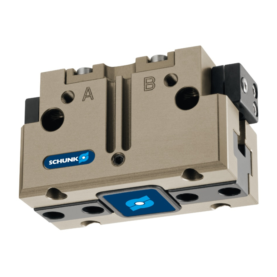
4 Design and description 4.1 Design 2-Finger Parallel Gripper Housing Air purge connection Compressed air main connection Base jaw 4.2 Description Universal 2-finger parallel gripper with T-slot guidance 14.00 | JGP | Assembly and Operating Manual | en | 389157... -
Page 20: Assembly
Connect the product via the hose-free direct connection. Ø Use O-rings from the accessory pack. ✓ Seal main air connections which are not required with locking ✓ screws. 14.00 | JGP | Assembly and Operating Manual | en | 389157... -
Page 21: Connections
Evenness of the product is mounted. mounting surface Requirements for evenness of the mounting surface (Dimensions in mm) Edge length Permissible unevenness < 100 < 0.02 > 100 < 0.05 14.00 | JGP | Assembly and Operating Manual | en | 389157... - Page 22 Centering sleeve Ø10 Ø14 Ø16 Ø16 Ø22 Thread in base jaws M10 M12 M12 M16 Mounting screw strength 12.9 class Max. depth of engagement from locating surface [mm] 14.00 | JGP | Assembly and Operating Manual | en | 389157...
- Page 23 DIN EN ISO 4762 according to Max. strength class 8.8 standard Centering sleeve Ø5 Ø6 Ø8 Ø8 Ø10 Ø12 Fitting bore for – – Ø4 – Ø5 Ø6 centering pin [mm] 14.00 | JGP | Assembly and Operating Manual | en | 389157...
- Page 24 Mounting screw according DIN EN ISO 4762 to standard Max. strength class 8.8 Centering sleeve Ø12 Ø14 Ø16 Ø22 Fitting bore for centering Ø6 Ø8 – Ø10 pin [mm] 14.00 | JGP | Assembly and Operating Manual | en | 389157...
-
Page 25: Pneumatic Connection
Air purge connection Hose-free direct connection O-ring Attachment Product Thread diameter of the air connections Item 40 64 80 R1/8" R1/8" R1/8" R1/8" R1/4" R1/4" M3 M5 M5 M5 14.00 | JGP | Assembly and Operating Manual | en | 389157... -
Page 26: Mounting The Sensor
Flexible position sensor FPS-F5 with FPS-S M8 Analog position sensor APS-M1 Optical distance sensor Analog position sensor APS-Z80 Radio system RSS R1/T2 with Reed switch RMS 80 Force-measuring jaw FMS 14.00 | JGP | Assembly and Operating Manual | en | 389157... -
Page 27: Setting Dimensions For Magnetic Switches
• In "Optimal Mode", the sensor identifies the optimal position in the groove itself. SCHUNK recommends "Optimal Mode" for setting the sensors. Further information on the installation of the sensor, Mounting programmable magnetic switch MMS 22-PI1 30] 14.00 | JGP | Assembly and Operating Manual | en | 389157... -
Page 28: Switch-Off Hysteresis For Magnetic Switches
Remove control cam (1) from the product, turn and re-insert it Ø into the product. Turn the screw (3) to push the position of the control cam (1). Ø 14.00 | JGP | Assembly and Operating Manual | en | 389157... -
Page 29: Mounting Magnetic Switch Mms 22
Secure the sensor 2 (1) using the set-screw (4). Ø Tightening torque: 10 Ncm Bring product into the "Gripper closed" or "Part gripped" Ø position and test the function. 14.00 | JGP | Assembly and Operating Manual | en | 389157... -
Page 30: Mounting Programmable Magnetic Switch Mms 22-Pi1
Hold teaching tool to the sensor 1 (1), to confirm the position. Ø The sensor 1 (1) has been taught in. ✓ Repeat steps for sensor 2. Ø 14.00 | JGP | Assembly and Operating Manual | en | 389157... -
Page 31: Mounting Programmable Magnetic Switch Mms 22-Pi2
OR: Slide the sensor (1) into the groove (2) until the sensor (1) stops at the T-nut (3). Secure the sensor (1) using the set-screw (4). Ø Tightening torque: 10 Ncm 14.00 | JGP | Assembly and Operating Manual | en | 389157... -
Page 32: Mounting Programmable Magnetic Switch Mms-P 22
OR: Slide the sensor (1) into the groove (2) until the sensor (1) stops at the T-nut (3). Secure the sensor (1) using the set-screw (4). Ø Tightening torque: 10 Ncm Adjust sensor (1), see sensor assembly and operating manual. Ø 14.00 | JGP | Assembly and Operating Manual | en | 389157... -
Page 33: Mounting Inductive Proximity Switch In 80
Switching point is set. ✓ Bring product into the "Gripper open" or "Part gripped" position Ø and test the function. 14.00 | JGP | Assembly and Operating Manual | en | 389157... - Page 34 NOTE If the switching position cannot be queried, it may be that the alignment of the control cam has to be changed, Turn control 28]. 14.00 | JGP | Assembly and Operating Manual | en | 389157...
-
Page 35: Mounting Reed Switch Rms 80
Switching point is set. ✓ Bring product into the "Gripper open" or "Part gripped" position Ø and test the function. 14.00 | JGP | Assembly and Operating Manual | en | 389157... - Page 36 NOTE If the switching position cannot be queried, it may be that the alignment of the control cam has to be changed, Turn control 28]. 14.00 | JGP | Assembly and Operating Manual | en | 389157...
-
Page 37: Mounting Flexible Position Sensor Fps
Slide the sensor (1) to the stop into the bracket (2). Ø Tighten the screw (3) on the bracket (2). Ø Tightening torque: 0.2 Nm Adjust sensor (1), see assembly and operating manual of the Ø sensor. 14.00 | JGP | Assembly and Operating Manual | en | 389157... -
Page 38: Mounting Analog Position Sensor Aps-M1
Tighten screw (4) and in doing so press the control cam (6) in Ø the direction of the gripper finger. Slide the sensor (1) to the stop into the bracket (2). Ø 14.00 | JGP | Assembly and Operating Manual | en | 389157... -
Page 39: Mounting Analog Position Sensor Aps-Z80
SCHUNK. Actual signal Optimum signal Stroke [mm] Analog signal on O.D. gripping Actual signal Optimum signal Stroke [mm] Analog signal on I.D. gripping 14.00 | JGP | Assembly and Operating Manual | en | 389157... - Page 40 Slide the sensor (1) to the stop into the bracket (2). Ø Tighten the screw (3) on the bracket (2). Ø Tightening torque: 0.2 Nm Adjust sensor (1), see assembly and operating manual of the Ø sensor. 14.00 | JGP | Assembly and Operating Manual | en | 389157...
-
Page 41: Mounting Optical Distance Sensor Oas
Assemble the sensor in place of the cover plate. To do this, use Ø the cover plate screws. Connect the sensor to the evaluation unit, see Translation of Ø Sensor Assembly and Operating Instructions. 14.00 | JGP | Assembly and Operating Manual | en | 389157... -
Page 42: Mounting The Radio System Rss-R1/T2
Screw gripper fingers onto the force-measuring jaws (1, 3). Ø Use centering sleeves between force-measuring jaw and ✓ gripper finger. Connect the evaluation unit, see Sensor Assembly and Ø Operating Instructions. 14.00 | JGP | Assembly and Operating Manual | en | 389157... -
Page 43: Troubleshooting
Clean and lubricate product. areas. Compressed air lines blocked. Check compressed air lines of damage. Mounting surface is not sufficiently flat. Check the evenness of the mounting surface. 14.00 | JGP | Assembly and Operating Manual | en | 389157... -
Page 44: Gripping Force Is Dropping
If, despite optimum air connections, the opening and closing times specified in the catalogue are not achieved, SCHUNK recommends the use of quick-air-vent- valves directly at the product. 14.00 | JGP | Assembly and Operating Manual | en | 389157... -
Page 45: Maintenance
Disassembly and assembly 46]. The seals are in the enclosed sealing kit., Seal kit 8]. Treat all grease areas with lubricant, Lubricants/Lubrication points 46]. Oil or grease external steel parts. 14.00 | JGP | Assembly and Operating Manual | en | 389157... -
Page 46: Lubricants/Lubrication Points
Unscrew the screws (40) and remove the cylinder piston (60) Ø from the housing (1). Press the piston (3) upward out of the housing (1). Ø Pull the base jaws (2) out of the housing (1). Ø 14.00 | JGP | Assembly and Operating Manual | en | 389157... - Page 47 Types 125–160: Remove the distance bolts (11) from the Ø housing (1). Press the piston (3) upward out of the housing (1). Ø Pull the base jaws (2) out of the housing (1). Ø 14.00 | JGP | Assembly and Operating Manual | en | 389157...
- Page 48 Unscrew screw (40) and remove cylinder piston (60) from the Ø housing (1). Press the piston (3) upward out of the housing (1). Ø Pull the base jaws (2) out of the housing (1). Ø 14.00 | JGP | Assembly and Operating Manual | en | 389157...
-
Page 49: Assembling The Product
Assembly with assembly device 50]. • Unless otherwise specified, secure all screws and nuts with Loctite no. 243 and tighten with the appropriate tightening torque. Tightening torque for screws 54] 14.00 | JGP | Assembly and Operating Manual | en | 389157... - Page 50 Screw in screw (45) and tighten with the appropriate tightening Ø torque, Tightening torque for screws 54]. Remove the device (100) and continue to assemble the gripper Ø in the opposite order to disassembly, Assembly drawing 54]. 14.00 | JGP | Assembly and Operating Manual | en | 389157...
- Page 51 Remove device. Ø Put sealing (32/34) in and mount the cover (9) using the screws Ø (46), Assembly drawing 54]. Further information Sizes 40 - 100 [} 52] Sizes 160-300 [} 53] 14.00 | JGP | Assembly and Operating Manual | en | 389157...
- Page 52 JGP 100 Screw for assembly device Item Designation Screw (DIN EN ISO 4762) M3 x 20 M3 x 25 M5 x 30 M5 x 35 M6 x 40 14.00 | JGP | Assembly and Operating Manual | en | 389157...
- Page 53 Screws for cylinder piston assembly device Item M8 x 60 M10 x 80 M12 x 90 M16 x 110 M8 x 65 M8 x 80 M10 x 95 M10 x 110 14.00 | JGP | Assembly and Operating Manual | en | 389157...
-
Page 54: Assembly Drawing
7.5 Assembly drawing The following figure is an example image. It serves for illustration and assignment of the spare parts. Variations are possible depending on size and variant. 14.00 | JGP | Assembly and Operating Manual | en | 389157... - Page 55 100 - 300 Item. 12 for sizes 40 - 80 Item. 32 for sizes 100 - 300 from size 200 for size 125 for size 160 14.00 | JGP | Assembly and Operating Manual | en | 389157...
-
Page 56: Translation Of Original Declaration Of Incorporation
Person authorized to compile the technical documentation: Robert Leuthner, Address: see manufacturer's address Lauffen/Neckar, September 2019 p.p. Ralf Winkler, Manager for development of gripping system components 14.00 | JGP | Assembly and Operating Manual | en | 389157... -
Page 57: Annex To Declaration Of Incorporation
1.3.1 Risk of loss of stability 1.3.2 Risk of break-up during operation 1.3.3 Risks due to falling or ejected objects 1.3.4 Risks due to surfaces, edges or angles 14.00 | JGP | Assembly and Operating Manual | en | 389157... - Page 58 Risk of slipping, tripping or falling 1.5.16 Lightning Maintenance 1.6.1 Machinery maintenance 1.6.2 Access to operating positions and servicing points 1.6.3 Isolation of energy sources 1.6.4 Operator intervention 1.6.5 Cleaning of internal parts 14.00 | JGP | Assembly and Operating Manual | en | 389157...
- Page 59 Supplementary essential health and safety requirements for machinery intended for underground work Supplementary essential health and safety requirements for machinery presenting particular hazards due to the lifting of persons 14.00 | JGP | Assembly and Operating Manual | en | 389157...
- Page 60 Notes Notes 14.00 | JGP | Assembly and Operating Manual | en | 389157...
Need help?
Do you have a question about the JGP and is the answer not in the manual?
Questions and answers