
Related Manuals for SCHUNK PZB-plus


Summary of Contents for SCHUNK PZB-plus
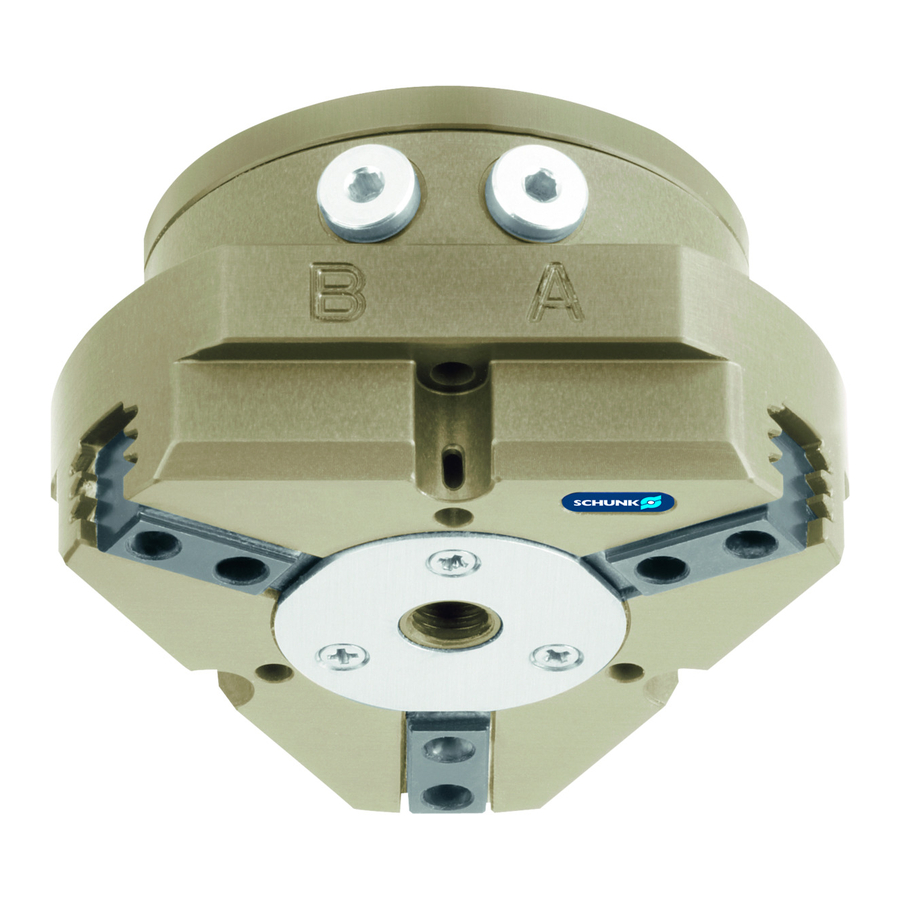
- Page 1 Translation of the original manual 3-Finger-Centric Gripper PZB-plus Assembly- and Operating Manual Superior Clamping and Gripping...
- Page 2 Imprint Copyright: This manual remains the copyrighted property of SCHUNK GmbH & Co. KG. It is solely supplied to our customers and operators of our products and forms part of the product. This documentation may not be duplicated or made accessible to third parties, in particu- lar competitive companies, without our prior permission.
-
Page 3: Table Of Contents
8 Trouble shooting ..................... 29 8.1 Module does not move? ..................29 8.2 The module does not travel through the entire stroke? ........29 8.3 Module opens or closes abruptly? ................. 30 8.4 The gripping force drops? ..................30 06.00|PZB-plus |en... - Page 4 9.5 Servicing and assembling the module ..............35 9.5.1 Screw tightening torques ................35 10 Assembly drawing ....................36 11 Sealing kit ........................ 37 12 Accessories kit ......................38 13 Translation of original declaration of incorporation ..........39 06.00|PZB-plus |en...
-
Page 5: About This Manual
Non-compliance will inevitably cause irreversible injury or death. WARNING Dangers for persons. Ignoring a safety note like this can lead to irreversible injury and even death. CAUTION Dangers for persons. Non-observance can cause minor injuries. NOTICE Material damage Information about avoiding material damage. 06.00|PZB-plus |en... -
Page 6: Variants
About this manual Variants This operating manual applies for the following variations • PZB-plus without gripping force maintenance • PZB-plus with gripping force maintenance "O.D. gripping" • PZB-plus with gripping force maintenance "I.D. gripping" • PZB-plus High-temperature version (HT) Applicable documents •... -
Page 7: Basic Safety Notes
• Observe Maintenance and lubrication intervals 31). • Make sure that the environment is free from splash water and vapors as well as from abrasion or processing dust. Exceptions are products that are designed especially for contaminated en- vironments. 06.00|PZB-plus |en... -
Page 8: Product Safety
2.4.3 Constructional changes, attachments, or modifications Additional drill holes, threads, or attachments that are not offered as accessories by SCHUNK may be attached only with permission of SCHUNK. Personnel qualification The assembly, initial commissioning, maintenance, and repair of the product may be performed only by trained specialist person- nel. -
Page 9: Using Personal Protective Equipment
• Perform maintenance, modifications, and additions outside the danger zone. • Secure the product during all operations against uncontrolled activation. • Take a precautionary approach by maintenance and disassembly. • Only specially trained staff should disassemble the product. 06.00|PZB-plus |en... -
Page 10: Variant Gripping Force Maintenance
Products with a mechanical gripping force maintenance can, dur- ing energy supply failure, still move independently in the direc- tion specified by the mechanical gripping force maintenance. • Secure the end positions of the product with SCHUNK SDV-P pressure maintenance valves. WARNING... -
Page 11: Warranty
• Observance of the ambient conditions and operating conditions ( 2.3, Page 7) • Observe the mandatory maintenance and lubrication intervals.( 9, Page 31) Parts touching the work piece and wearing parts are not part of the warranty. 06.00|PZB-plus |en... -
Page 12: Scope Of Delivery
Accessories Scope of delivery The scope of delivery includes • 3-Finger-Centric Gripper PZB-plus in the ordered model. • Accessory pack Accessories A wide range of accessories is available for this module. For information about which accessories can be used with the ap- propriate product version ☞... -
Page 13: Technical Data
0.5 - 1 Min. ambient temperature [°C] - 10 max. ambient temperature [°C] + 90 Noise emission [dB(A)] ≤ 70 IP rating More technical data are included in the catalog data sheet. Whi- chever is the latest version. 06.00|PZB-plus |en... -
Page 14: Assembly
Permissible unevenness < 100 < 0.02 > 100 < 0.05 Mounting The module can be mounted from the front or the rear. Assembly options The centring sleeves (55) and cylindrical pin (56) are included in the accessories kit. 06.00|PZB-plus |en... - Page 15 NOTE • When mounting from the back, fasten the module by means of the provided fixing bore. • Fasten the module using the provided mounting holes. • Fasten the top jaws using the provided mounting holes. 06.00|PZB-plus |en...
-
Page 16: Mounting Of The Gripper By Using A Spring Loaded Pressure-Piece
Mounting the pressure piece is described in the insert "Installation instructions - pressure piece", which is included in the pressure piece's scope of delivery. 06.00|PZB-plus |en... -
Page 17: Air Connections
13). air connections Thread diameter of the air connections Item Connection PZB-plus 100 125 160 200 240 300 Hose connection (A= open, B = closed) G1/8" G1/4" Air purge connection Hose-free direct connection (a= open, b = closed) 06.00|PZB-plus |en... -
Page 18: Sensors
• If you require further information on sensor operation, contact your SCHUNK contact person or download information from our homepage. • Technical data for the sensors can be found in the data sheets (included in the scope of delivery). - Page 19 Mounting of the The switching points of the “open” and “closed” position were set proximity switch at the factory by SCHUNK. Gripper open: 1 Push the proximity switch 1 (14) to the stop in the bracket (17) 2 Fasten the proximity switch by tightening the screw (13).
- Page 20 6 Move the switching cam (15) inward again until the proximity switch starts to switch. 7 Secure this switching point by tightening the screw (42). 8 Test the function by opening the gripper and then closing it again. 06.00|PZB-plus |en...
-
Page 21: Magnetic Switch Mms 22 / Rms 22
• Then, the positions of the magnetic switch have to be set The RMS sensors have a larger hysteresis than the MMS sensors. This means that short gripper strokes may not be able to be moni- tored with the RMS sensors. 06.00|PZB-plus |en... - Page 22 3 By tightening the set screw (3), fix the magnetic switch 2 (2) in this position in the groove (4). 4 Test the function by opening the gripper and then closing it again. 06.00|PZB-plus |en...
-
Page 23: Programmable Magnetic Switch (Mms-P)
(12). 5 Test the function by closing the gripper and then opening it again. 7.4.3 Programmable magnetic switch (MMS-P) Programmable magnetic switch MMS-P 22 mounting screw Teach-button Center sensor elements LED display LED display Ribs for cable ties 06.00|PZB-plus |en... - Page 24 Ferromagnetic material changes the switching positions of the sensor. For example: Adapter plate made of ordinary steel. At ferromagnetic adapter plates: • First module mounted on adapter plate • Afterwards setting of the position of the magnet switch. 06.00|PZB-plus |en...
- Page 25 (bottom edge of gripper up to front side of sensor) or according to dimension l1 (bottom edge of gripper up to double arrow on sensor) and then clamp with the mounting screw. 3 Fix the sensor with an Allen wrench. 06.00|PZB-plus |en...
- Page 26 Assembly Type dimension dimension Type dimension dimension PZB-plus 50 15.4 24.3 PZB-plus 125 25.6 34.5 PZB-plus 50 AS 25.4 34.3 PZB-plus 125 AS 52.0 60.9 PZB-plus 50 IS 25.1 34.0 PZB-plus 125 IS 52.0 60.9 PZB-plus 64 17.4 26.3 PZB-plus 160 31.2...
- Page 27 (i.e. by shielding). Frequent types of disturbances are change in tempera- ture and electro-magnetic influences. Within the closest fine-teach mode, SCHUNK cannot guarantee EMC-compatibility any more. The hysteresis adjustment is used for the manual adjustment of the switching points (if necessary).
-
Page 28: Flexible Position Sensor Fps
Mounting kit To use the flexible position sensor FPS-M8, the grippers have to be retrofitted with a special mounting kit. This mounting kit is available from SCHUNK (see catalog). Mounting of the mounting kit 1 Remove the switching cam (21) and the screw (38) on one site of the gripper. -
Page 29: Trouble Shooting
Component is broken, e.g. through over- Replace component or send the module loading with a repair order to SCHUNK. Ensure that the module was only used within its defined application parameters. The module does not travel through the entire stroke? -
Page 30: Module Opens Or Closes Abruptly
Flow rate of valve is sufficiently large relative to the compressed air consumption. If, despite of optimal air connections, the open- ing and closing times are not achieved according to the catalog, we recommend the use of quick exhaust valves direct at the module. 06.00|PZB-plus |en... -
Page 31: Maintenance And Care
The base jaws and the guides in the housing are matched to each other. To have these parts replaced, send the complete module along with a repair order to SCHUNK. Maintenance of module with gripping force maintenance "I.D. gripping" (I.D.) and "A.D. gripping" (A.D.) The pistons have to be aligned using an assembly device. -
Page 32: Lubricants/Lubrication Points
(50). 7 Unscrew the groove nut (13) and remove the cylinder piston (6) from the housing. 8 Press the piston (3/8) upward out of the housing (50). 9 Pull the base jaws (2) out of the housing (50). 06.00|PZB-plus |en... -
Page 33: Version With Gripping Force Maintenance "I.d. Gripping
12 Remove the cylinder piston (10) out of the housing (50). 13 Remove the distance bolts (25) from the housing (50). 14 Press the piston (3/8) upwards and out of the housing (50). 15 Pull the base jaws (2) out of the housing (50). 06.00|PZB-plus |en... -
Page 34: Version With Gripping Force Maintenance I.d
9 Unscrew the groove nut (13) and remove the cylinder piston (6) from the housing. 10 Press the piston (3/8) upwards and out of the housing (50). 11 Pull the base jaws (2) out of the housing (50). 06.00|PZB-plus |en... -
Page 35: Servicing And Assembling The Module
• Unless otherwise specified, secure all screws and nuts with Loc- tite no. 243 and tighten with the appropriate tightening torque ( 9.5.1, Page 35). 9.5.1 Screw tightening torques Position of the position numbers( 10, Page 36) (Values in Nm) Item PZB-plus 06.00|PZB-plus |en... -
Page 36: Assembly Drawing
Wearing part, replace during maintenance. Included in the seal kit. Seal kit can only be ordered completely. in sizes 100 - 300 in sizes 80 - 300 **** Positions are adapted to each other and can not be replaced by the customer. 06.00|PZB-plus |en... -
Page 37: Sealing Kit
Sealing kit Sealing kit ( 10, Page Contents of the seal kit 36). ID.-No. of the seal kit Seal kit for ID number PZB-plus 50 5518602 PZB-plus 64 5518603 PZB-plus 80 5518604 PZB-plus 100 5518605 PZB-plus 125 5518606 PZB-plus 160... -
Page 38: Accessories Kit
Accessories kit Accessories kit Content of the accessories pack: • 6 x Centering sleeves for mounting • 2 x O-ring for hose-free direct connection • 2 x screw plug for hose connection • 2x Cylinder pins for mounting 06.00|PZB-plus |en... -
Page 39: Translation Of Original Declaration Of Incorporation
Translation of original declaration of incorporation in terms of the Directive 2006/42/EG, Annex II, Part 1.B of the European Parliament and of the Council on machinery. Manufacturer/ SCHUNK GmbH & Co. KG Spann- und Greiftechnik Distributor Bahnhofstr. 106 – 134 D-74348 Lauffen/Neckar... - Page 40 06.00|PZB-plus |en...
Need help?
Do you have a question about the PZB-plus and is the answer not in the manual?
Questions and answers