
Related Manuals for Edgetech PORT-LF


Summary of Contents for Edgetech PORT-LF
- Page 1 PORT-LF U S E R H A R D W A R E M A N U A L 0008595_REV_F 2/16/2024 EdgeTech 4 Little Brook Road West Wareham, MA 02576 Tel: (508) 291-0057 Fax: (508) 291-2491 www.EdgeTech.com...
- Page 2 The information, figures, and specifications in this manual are proprietary and are issued in strict confidence on condition that they not be copied, reprinted, or disclosed to a third party, either wholly or in part, without the prior written consent of EdgeTech. Any reproduction of EdgeTech-supplied software or file sharing is strictly prohibited.
-
Page 3: Attention - Read This First
ATTENTION – READ THIS FIRST! All personnel involved with installing, operating, or maintaining the equipment described in this manual should read and understand the warnings and cautions provided below. CAUTION! This equipment contains devices that are extremely sensitive to static electricity. Therefore, extreme care should be taken when handling them. -
Page 4: Hardware Variations And Compatibility
HARDWARE VARIATIONS AND COMPATIBILITY The PORT-LF contains both standard and proprietary hardware. At times, EdgeTech may change the standard components due to their availability or performance improvements. Although the component manufacturers and their models and styles may change from unit to unit, replacement parts will generally be interchangeable. -
Page 5: About This Document
We take pride in the products we manufacture and want you to be entirely satisfied with your equipment. Purpose of this Manual The purpose of this manual is to provide the user with information on the setup and use of EdgeTech’s PORT-LF. Although this manual encompasses the latest operational features of the PORT-LF, some features may be periodically upgraded. -
Page 6: Warranty Statement
All equipment manufactured by EdgeTech is warranted against defective components and workmanship for a period of one year after shipment. Warranty repair will be done by EdgeTech free of charge. Shipping costs are to be borne by the customer. Malfunction due to improper use is not covered in the warranty, and EdgeTech disclaims any liability for consequential damage resulting from defects in the performance of the equipment. -
Page 7: Software Service Overview
EdgeTech provides software services free of charge. This software agreement does not address customer- specified modifications or enhancements. These services may be ordered separately. Furthermore, EdgeTech software upgrades are meant for the sole use of EdgeTech customers. Any reproduction of EdgeTech-supplied software or file sharing is strictly prohibited. -
Page 8: Returned Material Authorization
Refer to the RMA number on all documentation and correspondences. All returned materials must be shipped prepaid. Freight collect shipments will not be accepted. All equipment should be adequately insured for shipping, but equipment belonging to EdgeTech must be insured for full value. -
Page 9: Customer Service
CUSTOMER SERVICE Customer service personnel at EdgeTech are always eager to hear from users of our products. Your feedback is welcome and is a valuable source of information that we use to improve these products continually. Therefore, we encourage you to contact EdgeTech Customer Service to offer any suggestions... -
Page 10: Company Background
— for the acquisition of underwater data, including marine, estuarine, and coastal applications — for over 50 years. EdgeTech responds to the needs of the scientific, naval, and offshore communities by providing industry- leading equipment — such as sub-bottom profilers, side scan sonar, acoustic releases, USBL positioning systems, and bathymetric systems —... -
Page 11: Table Of Contents
TABLE OF CONTENTS ATTENTION – READ THIS FIRST! ......................iii Warnings, Cautions, and Notes ........................ iii HARDWARE VARIATIONS AND COMPATIBILITY .................. iv ABOUT THIS DOCUMENT ........................v Purpose of this Manual ..........................v Liability ..............................v Revision History ............................v WARRANTY STATEMENT ........................ - Page 12 O-Ring Care and Considerations ..................5-34 5.4.2 Additional O-Rings ......................5-35 5.4.3 Servicing the O-Rings ......................5-35 General Cleaning and Inspection ..................... 5-36 5.5.1 Inspection Particulars ......................5-36 EdgeTech Tips: ......................... 5-37 PORT-LF Kits and Options ....................5-38 PORT-LF 0008595_REV_F...
- Page 13 Spares Kit ..........................5-38 O-Ring Kit ..........................5-38 PORT-LF Remote Release Kit Option ..................A-1 PORT-LF Tandem Kit Option ..................... A-1 PORT-LF Strongback Option ..................... A-1...
-
Page 14: List Of Figures
Figure 2-2: Standard Port LF ICD ........................ 2-7 Figure 2-3: Deep Release Port LF ICD ......................2-8 Figure 2-4: PORT-LF Callout Assembly Drawing Page 1 of 2 0008118 ............2-9 Figure 2-5: PORT-LF Callout Assembly Drawing Page 2 of 2 0008118 ............. 2-10 Figure 3-1: PACS Deck Box ........................ - Page 15 Figure 5-23: ASSY Top Port LF with Remote Release ................A-3 Figure 5-24: PORT-LF Tandem Kit ......................A-1 Figure 5-25: PORT-LF Tandem Assembly ICD .................... A-1 Figure 5-26: PORT-LF Tandem Assembly Diagram ..................A-2 Figure 5-27: PORT-LF Strongback Kit ICD ....................A-1...
- Page 16 Figure 5-28: PORT-LF Strongback Assembly Drawing ................A-2 PORT-LF 0008595_REV_F...
-
Page 17: List Of Tables
Table 2-7: Power Specifications ......................... 2-6 Table 2-8: Environmental Specifications ....................2-6 Table 3-1: Status Reply Meanings ......................3-12 Table 5-1: Port-LF Spares Kit ........................5-38 Table 5-2: Port-LF O-Ring Kit ........................5-38 Table 5-3: PORT-LF Strongback Kit ......................A-1... -
Page 18: Overview
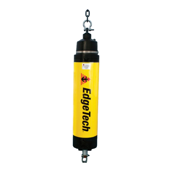
Figure 1-1: PORT-LF commands and receive information. The PORT-LF is very versatile. It is designed for use as an instrument location and recovery system on oceanographic moorings and platforms. Additionally, the precision, high-output power transponder feature makes this instrument ideal for use in Long Baseline (LBL) Positioning and Navigation Systems. -
Page 19: Basic Functionality
The RELEASE command causes the instrument's threaded release shaft to rotate and push off a threaded release link. While releasing, the PORT-LF will ping once for every rotation of the release shaft. This confirms that the shaft is turning and the Release Link is being pushed off. Once the threaded link is completely pushed out, the instrument is free. -
Page 20: Specifications
2.0 SPECIFICATIONS Specifications for the PORT-LF are provided in the subsections that follow. 2.1 Mechanical Specifications SPECIFICATION VALUE Depth Rating 3,500 m (11,480 ft) Maximum Release Threshold 350 kg (770 lb) Maximum Static Load 750 kg (1,650 lb) Overall Length... -
Page 21: Printed Circuit Board (Pcb)
2.2 Printed Circuit Board (PCB) The PCB connectors on the PORT-LF electronic circuit board are shown below 2-1). IGURE Motor Connection Transducer Connection Battery Connection Figure 2-1: PORT-LF PCB Connectors 2.3 Acoustic Specifications 2.3.1 Command Receiver SPECIFICATION VALUE Sensitivity 78 dB re 1 µPa... -
Page 22: E-Bacs Command Structure
NOTE: The 8011M and PACS LF deck box firmware must be up to date to send these commands. 8011M firmware should be 1.701 or later, and the PACS LF should be 2.01 or later. Contact EdgeTech USTOMER ERVICE for details on updating the firmware on your deck box. -
Page 23: Transponder Specifications
1 second Table 2-6: Transponder Specifications 2.3.7 Power Supply Specifications The PORT-LF uses a welded alkaline Battery Pack as a power supply. Specifications for this battery pack are shown in the following table: SPECIFICATION VALUE Design Life (@ 0° C) 2 years Design Life (@ 0°... -
Page 24: Figure 2-2: Standard Port Lf Icd
Figure 2-2: Standard Port LF ICD... -
Page 25: Figure 2-3: Deep Release Port Lf Icd
Figure 2-3: Deep Release Port LF ICD... -
Page 26: Figure 2-4: Port-Lf Callout Assembly Drawing Page 1 Of 2 0008118
Figure 2-4: PORT-LF Callout Assembly Drawing Page 1 of 2 0008118... -
Page 27: Figure 2-5: Port-Lf Callout Assembly Drawing Page 2 Of 2 0008118
2-10 Figure 2-5: PORT-LF Callout Assembly Drawing Page 2 of 2 0008118... -
Page 28: Installation
ERVICE 3.2 Acoustic Considerations Efforts should be made to ensure a clear acoustic path between the PORT-LF Transducer and the source (typically a dunking transducer from a deck Unit). Structural elements of a mooring system, which have significantly different acoustic impedance than seawater, will cause absorption or reflection of acoustic... -
Page 29: Mechanical Considerations
3.5 Monitoring Tilt With Status Reply The PORT-LF is equipped with sensors that monitor the system's tilted or not tilted orientation and release shaft rotation. This information allows the unit to send a coded status reply based on the instrument's orientation and to emit one ping each time the release shaft completes a rotation. - Page 30 3-13 The tilt sensor is a 45° mechanical switch mounted on the release circuit board assembly in the standard instrument configuration. The unit is defined as “not tilted” with the release mechanism down. Optical tilt switches are available for applications requiring a narrower maximum allowable angle of tilt. The switch can also be installed at different angles to change the standard orientation.
-
Page 31: Operating Instructions
1. Remove the anti-rotation block (black Delrin block that keeps the release link from turning) from the release end of the instrument by unscrewing the two nylon screws that hold it in place, as shown in 4-1. IGURE [2] Nylon Screws Figure 4-1: Unscrew the [2] Nylon Screws On Anti-Rotation Block PORT-LF 0008595_REV_F... -
Page 32: Removing The Release End Cap
4-15 2. The purge port plug will be visible once the anti-rotation block has been removed. Pull the purge port plug from the end cap, as shown in 4-2. IGURE Purge Port Plug Figure 4-2: Removing Purge Port Plug 4.1.2 Removing the Release End Cap Remove the Kynar retaining rod (white plastic rod) from the release end by gripping the end of the rod with pliers... -
Page 33: Connecting Power
4.1.3 Connecting Power CAUTION: EdgeTech suggests using a grounded wrist strap to protect the electronics board from static electricity when handling it. The electronics board assembly and battery pack are mounted to an aluminum plate attached to the release end cap. A cable with a connector is used to connect the battery pack to the electronics board. -
Page 34: Figure 4-6: Battery Connection Location On Port Lf Electronics Board
4-17 Battery Connection Figure 4-6: Battery Connection Location On Port LF Electronics Board Figure 4-7: Gently Line Up the Connector to the 3-Pins and Press In Figure 4-8: Properly Seated Battery Connection... -
Page 35: Closing The Release
Electronic Chassis Support Bracket Transducer Cable Figure 4-9: Transducer Cable is Run Through the Electronic Chassis Support Bracket CAUTION: Ensure the grounding spring is inside the release when closed. Be sure not to scratch the housing threading with it. PORT-LF 0008595_REV_F... -
Page 36: Figure 4-10: Consider The Grounding Spring When Inserting The Release End Cap
4-19 Grounding Spring Figure 4-10: Consider the Grounding Spring When Inserting the Release End Cap 1. Gently guide the electronics assembly back into the housing. Figure 4-11: Gently Pushing The Transducer Into the Housing 2. Press the grounding spring in while guiding the end cap further in. The grounding spring must be inside the housing when the release is closed and touching the bare aluminum band 4-13 IGURE... -
Page 37: Figure 4-12: Gently Press The Grounding Spring In While Closing
3. As you gently but firmly push the endcap into the housing, ensure that the end cap orientation 4-15. key matches the housing’s insert. This ensures proper alignment, as shown in IGURE End Cap Orientation Key Lined Up With The Housing Insert Figure 4-14: End Cap Orientation Key and Housing Insert Lined Up PORT-LF 0008595_REV_F... -
Page 38: Purging The Device And Sealing The Port Lf: Leak And Condensation Prevention
4-21 End Cap Orientation Key and Housing Insert Properly Mated Figure 4-15: End Cap Orientation Key Mated into The Housing Replacing The Kynar Rod: 4. While holding the release end cap in place, insert the Kynar retaining rod flat into the slot and slide in until it emerges from the slot. -
Page 39: Figure 4-19: Installing Anti-Rotation Block By Threading [2] Nylon Screws
Figure 4-19: Installing Anti-Rotation Block By Threading [2] Nylon Screws 7. At this point, it is good practice to perform an air acoustic test of the system by running through the command set for the PORT-LF. Refer to this manual’s section for detailed... -
Page 40: Arming The Port Lf
4-23 4.2 Arming The Port LF The release mechanism is armed by installing a release link. Items required for arming: One (1) Release Link • Silicone grease • Phillips screwdriver (#1 Phillips preferred) • To Arm The Instrument: 1. Remove the anti-rotation block from the release end of the instrument (black Delrin block that keeps the release link from turning) by unscrewing the two nylon screws that hold it in place. -
Page 41: Figure 4-21: Release Shaft And [2] Anodes Locations
3. Grease the threads on the shaft and inside the link with silicone grease. 4. Thread the release link onto the release shaft until it bottoms out, then unscrew it ¼ turn. Figure 4-22: Thread Release Link Onto Release Shaft PORT-LF 0008595_REV_F... -
Page 42: Acoustic Air Testing
For this reason, it is necessary to place the source (deck unit transducer or speaker) within a meter or two of the PORT-LF transducer, with no obstructions to the acoustic path. Depending on the environment, some experimentation may be necessary to find a suitable location. -
Page 43: Post Deployment
A visual inspection of the release housing and release mechanism should be performed to detect any signs of damage, excessive wear, corrosion, etc. If the PORT-LF will not be used again soon, the unit should be turned off by disconnecting the batteries to preserve battery life. -
Page 44: Maintenance
5-27 5.0 MAINTENANCE The PORT-LF is a durable instrument that requires minimal maintenance. Regular maintenance tasks should include pre-deployment preparations, checks, and post-deployment cleaning. Larger Important but less frequent tasks include battery replacement, O-ring care and maintenance, and general cleaning, inspection, and lubrication of operational elements. -
Page 45: Figure 5-2: Kynar Rod Removal On Transducer End
Figure 5-2: Kynar Rod Removal On Transducer End Figure 5-3: Transducer End Cap Carefully Slid Away from the Release Housing 5. The unit is now completely disassembled. Any maintenance or part inspection can now be completed. Faulty, questionable, or worn parts should always be replaced. PORT-LF 0008595_REV_F... -
Page 46: Port-Lf Assembly
5-29 5.2 PORT-LF Assembly The following instructions detail the complete assembly of the PORT-LF. Suggested tools include: • Pliers • Philips Screwdriver CAUTION! The transducer end should be put back into the housing first to ensure no damage to cables and internal components occurs. -
Page 47: Figure 5-5: Feed The Transducer Cable From The Transducer Side Of The Housing To The Release Side
IGURE housing insert that are properly mated. End Cap Orientation Key Lined Up With The Housing Insert Figure 5-6: Gently Guide the Transducer End Cap into the Housing without the Aluminum Band PORT-LF 0008595_REV_F... -
Page 48: Figure 5-7: Transducer End Cap Orientation Key And Housing Insert, Properly Mated
5-31 End Cap Orientation Key and Housing Insert Properly Mated Figure 5-7: Transducer End Cap Orientation Key and Housing Insert, Properly Mated 3. While holding the transducer end cap in place, insert the Kynar retaining rod flat into the slot and slide in until it emerges from the slot. -
Page 49: Battery Replacement
REVENTION 5.3 Battery Replacement The Port-LF uses a welded battery pack of standard “AA” alkaline batteries. The battery pack is located on the back of the electronics assembly, so the PORT-LF must be dissembled, and the electronics chassis must be pulled out to access it and then reassembled when complete. -
Page 50: Figure 5-12: Disconnecting Transducer Cable From Electronics Board
5-33 Slowly and carefully remove the electronics chassis from the housing and flip it so the battery • side can be worked on. Figure 5-12: Disconnecting Transducer Cable From Electronics Board 2. The battery pack is secured to the chassis by [2] retainer brackets attached to the chassis with [2] screw assemblies each. -
Page 51: O-Rings
Inspect for scratches or nicks that could impair the O-ring’s ability to provide a seal. Apply a light coat of O-ring lubricant (EdgeTech recommends Parker’s Super O-lube; be sure to use only silicone grease) to the housing and O-ring to facilitate insertion of the end cap. Make sure the lubricant is compatible with Nitrile rubber. -
Page 52: Additional O-Rings
(JP1). Once disconnected, the transducer end cap should be able to be slid out, giving you access to service the O-rings. Figure 5-17: Disconnecting the Transducer Cable 4. Clean, Inspect, and lightly grease the O-rings. EdgeTech recommends the use of Parker’s Super O-lube silicone compound grease. O-Rings... -
Page 53: General Cleaning And Inspection
Check the housing for signs of corrosion or damage to the hard coat. • o If there is damage to the paint and/or hard coat on the outside of the release, use epoxy- based paint to seal the surface. PORT-LF 0008595_REV_F... -
Page 54: Edgetech Tips
Field trials show these glands can become tightly packed with fine sediment under certain environmental conditions. The buildup of this sediment can make Kynar retention Rod removal difficult. EdgeTech recommends covering the glands by wrapping 2” electrical tape around the housing to prevent this. -
Page 55: Port-Lf Kits And Options
5-38 A.0 PORT-LF Kits and Options A.1 Spares Kit PART NUMBER DESCRIPTION QUANTITY 0008466 REV D ASSY TOP KIT SPARES PORT LF RELEASE 0005947 O-RING BUNA-N 70 2-240 STANDARD ROUND BLACK 0003242 O-RING BUNA-N 90 8-240 BACKUP PARBAK ROUND BLACK... -
Page 56: Port-Lf Remote Release Kit Option
A.3 PORT-LF Remote Release Kit Option The remote release physically separates the release and transducer ends of the PORT-LF for use in certain operations. Figure 5-21: Port LF Remote Release ICD... -
Page 57: Figure 5-22: Port Lf With Remote Release Icd
Figure 5-22: Port LF With Remote Release ICD... -
Page 58: Figure 5-23: Assy Top Port Lf With Remote Release
Figure 5-23: ASSY Top Port LF with Remote Release... -
Page 59: Port-Lf Tandem Kit Option
Tandem Assembly. When a Tandem is used with a mooring, it can be recovered by releasing either PORT-LF release. In the event of a failure of the mooring to detach from the anchor, the RELEASE command can be sent to both PORT-LFs, freeing both from the oblong ring and chain assembly. -
Page 60: Figure 5-25: Port-Lf Tandem Assembly Icd
Figure 5-25: PORT-LF Tandem Assembly ICD... -
Page 61: Figure 5-26: Port-Lf Tandem Assembly Diagram
Figure 5-26: PORT-LF Tandem Assembly Diagram... -
Page 62: Port-Lf Strongback Option
HARDWARE WASHER STD FLAT 0.375 316 SS 0008192 HARDWARE BOLT STD HEX 3/8-16 2.25 INCH 316 SS 0008174 CLAMP PORT LF STRONGBACK DELRIN 0006595 RTV 133 BLACK 0026286 LUBRICANT AQUA SHIELD BOTTLE 0017674 DOC DRAWING ICD PORT LF STRONGBACK KIT Table 5-3: PORT-LF Strongback Kit... -
Page 63: Figure 5-27: Port-Lf Strongback Kit Icd
Figure 5-27: PORT-LF Strongback Kit ICD... - Page 64 Figure 5-28: PORT-LF Strongback Assembly Drawing...
Need help?
Do you have a question about the PORT-LF and is the answer not in the manual?
Questions and answers