
Related Manuals for Teldat Regesta Smart PLC

Summary of Contents for Teldat Regesta Smart PLC
- Page 1 Manual Teldat S.A. Regesta Smart PLC Installation Manual Copyright© Teldat dm339-I Version 1.4 10/2023 Teldat S.A. Regesta Smart PLC...
- Page 2 This publication is subject to change. Teldat S.A. offers no warranty whatsoever for information contained in this manual. Teldat S.A. is not liable for any direct, indirect, collateral, consequential or any other damage connected to the deliv- ery, supply or use of this manual.
-
Page 3: Table Of Contents
Disconnecting ........Regesta Smart PLC... - Page 4 RS-485 serial port connectors ......A.1.8 Power supply connector ....... . Regesta Smart PLC...
- Page 5 Radio Information ....... . . 38 RF WWAN specifications ....... Regesta Smart PLC...
-
Page 6: About This Manual
1 About this Manual Teldat S.A. Chapter 1 About this Manual This is the installation manual for the Regesta Smart PLC router and contains information on correctly installing the device in a working environment. 1.1 Supported devices The information provided in this installation manual specifically pertains to the Regesta Smart PLC Series. -
Page 7: Safety Warnings
1 About this Manual Teldat S.A. 1.8 Safety warnings Connecting Disconnecting "Conectar" "Desconectar" Regesta Smart PLC... - Page 8 1 About this Manual Teldat S.A. Regesta Smart PLC...
-
Page 9: Related Documentation
1 About this Manual Teldat S.A. 1.9 Related documentation Teldat Dm704-I Configuration and Monitoring Teldat Dm709-I LAN Interfaces Teldat Dm712-I SNMP Agent Teldat Dm781-I Cellular Interface Teldat Dm748-I Software Updating Teldat Dm753-I Syslog Client Teldat Dm823-I PLC Gateway 1.10 Technical support Contact information: Web: http://www.teldat.com... -
Page 10: Product Overview
DLMS client) and smart meters registered on a PLC PRIME network (controlled by the Regesta Smart PLC) to communicate. In this scenario, the Regesta Smart PLC acts as the Base Node. The commu- nication is facilitated through a TCP transport layer for DLMS, with extensions for optimally multiplexing IEC 61334-4-32 connections (also known as Ticket 67) over a Wireless WAN (WWAN) data network on private or public networks, or a LAN connection. -
Page 11: Device Models
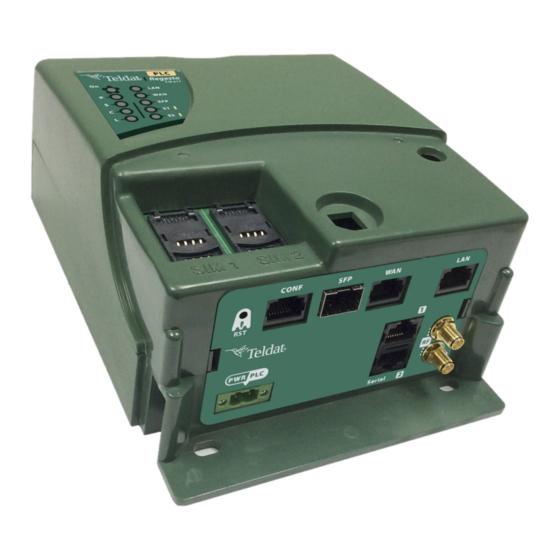
2 Product Overview Teldat S.A. Fig. 3: Regesta Smart PLC 2.2 Device models The following table lists the different models of the Regesta Smart PLC router that are available. Regesta Smart PLC models Code Description RWRTHR2ZAC-PLC Regesta Smart PLC 1 LAN Gigabit Ethernet port, 1 WAN Combo Gigabit Ether- net port, 1 RS232, AC powered (110 - 240 VAC). -
Page 12: Components
During startup mode, LED L will light up in green. Once the device has successfully booted up, the LEDs will indicate the following: LEDs Associated Inter- Status Description face Power Device is not powered on. Green Device is powered on. Regesta Smart PLC... - Page 13 Green Ethernet SFP connection (link) is established Multi standard seri- Serial port 1 is disabled or not initialized. al interface 1 Green Port is in active state, shows interface activity: • Steady: Data is not being transferred. Regesta Smart PLC...
-
Page 14: Connector Panel
(This connector can also be used as an RS-232 asynchronous DCE serial port.) For more information about the CONF connector, please refer to: Console connector as serial port (CONF connector) on page 23. Configuration connector on page 34. Configuration interface on page 37. Regesta Smart PLC... - Page 15 RS-232 serial interface on page 37. RS485 option RS-485/RS-422 serial port on page 24. RS-485 serial port connectors on page 35. RS-485 serial interface on page 37. RF/WWAN antenna connectors for the Cellular interface, depending on the model. Regesta Smart PLC...
-
Page 16: Underside Panel
Wall mounting on page 16. The platform on which the product information label is affixed. This label contains details such as the device model, MAC address, serial number, and more. Regesta Smart PLC... -
Page 17: Power Supply
2 Product Overview Teldat S.A. 2.5 Power supply The Regesta Smart PLC AC version is powered by an external AC power source. The nominal power voltages that it supports are 110-240 V AC. 2.5.1 Dying gasp option The Regesta Smart PLC can be enhanced with an optional Dying Gasp board, which can send an alarm signal in case of power failures or if the power supply cable is removed. -
Page 18: Installing The Router
3 Installing the Router Teldat S.A. Chapter 3 Installing the Router This chapter describes the steps to successfully install the Regesta Smart PLC router. It is divided into the following sections: • Workplace conditions on page 13. • Removing/Installing the connector protector on page 13. - Page 19 3 Installing the Router Teldat S.A. Removing the protective case Fig. 7: Slide the case up as shown below: Sliding the case up Fig. 8: Regesta Smart PLC...
-
Page 20: Installing A Din Rail Mount Accessory
3.3 Installing a DIN rail mount accessory The Regesta Smart PLC can easily be mounted on a standard DIN rail using a special kit included with the device. The kit contains all the necessary components, including 2 screws for securely attaching the rail mount to the device. -
Page 21: Wall Mounting
Fig. 12: 3.4 Wall mounting The Regesta Smart PLC features 3 wall mounting holes. To ensure a secure attachment, it is necessary to install screws into these holes. Before mounting the device on the wall, please remove the protective casing. - Page 22 3 Installing the Router Teldat S.A. Fig. 13: Holes for wall mounting. Regesta Smart PLC...
-
Page 23: Connecting The Router
4 Connecting the Router Teldat S.A. Chapter 4 Connecting the Router This chapter provides a detailed guide on connecting the Regesta Smart PLC router to Ethernet devices and net- works. Within this chapter, you will find the following sections: •... -
Page 24: Power Connector Cable
The data connections found in the Regesta Smart PLC include. 4.2.1 LAN connection The Regesta Smart PLC comes equipped with a 10/100/1000 BaseT Gigabit Ethernet port. This port supports auto- matic MDI/MDIX to connect to a local area network (LAN). -
Page 25: Wan Connections
Fig. 15: 4.2.2 WAN connections The Regesta Smart PLC features a single Ethernet COMBO Gigabit interface for WAN connections. This port in- cludes two connectors: an SFP connector for optical links and and RJ-45 for 10/100/1000 Base-T links. It is import- ant to note that these connectors cannot be used simultaneously. -
Page 26: Plc Connection
4.2.4 WWAN antenna connections (RF connectors) Certain models of the Regesta Smart PLC router have a pair of RF antenna connectors. The antennas are seam- lessly attached and detached by securely screwing and unscrewing them into the designated RF1 or RF2 connectors located on the device's connector panel. - Page 27 Teldat S.A. nector is linked to the AUX connector. By using these antennas in the Regesta Smart PLC router, the reception and transmission of signals by the WWAN module is significantly improved. To enhance signal quality for cellular technologies such as HSUPA and LTE, the Regesta Smart PLC includes two WWAN/RF connectors.
-
Page 28: Serial Port Connections
4.2.5 Serial port connections The Regesta Smart PLC is equipped with three RJ45 connectors to provide serial ports. However, depending on the model, the two RJ45 connectors labeled "Serial" may not be functional. 4.2.5.1 Console connector as serial port (CONF connector) The console port can be converted into an RS-232 asynchronous DCE serial port. -
Page 29: Installing The Sim Card
4.3 Installing the SIM card The Regesta Smart PLC features a Wireless WAN interface that requires at least one SIM card to be inserted for op- eration. However, in certain countries, CDMA services provided by some operators do not require the use of SIM cards.The Regesta Smart PLC features two SIM trays placed beneath the protective case, conveniently labeled... -
Page 30: Identifying The Sim Trays
After removing the case, you will have a clear view of the elements depicted below. The Regesta Smart PLC incorporates 2 SIM cards, providing the flexibility to execute various configurations. For in- stance, by installing two SIM cards, one can serve as a backup. To set up this configuration, you need to assign a separate tray for each SIM, as they have distinct configuration parameters. -
Page 31: Rst Button
Remember that it can be accessed from the WAN port. 4.5 Dying gasp alarm The Regesta Smart PLC offers the option to add a board that enables an alarm to be triggered in case of a power outage or if the power supply cable is removed. -
Page 32: Troubleshooting
For further guidance on SNMP configuration, consult the “Teldat Dm712-I SNMP Agent” manual. (3) If necessary, configure and enable the Syslog feature and server. For additional information on the Syslog feature, please refer to the “Teldat Dm753-I Syslog Client” manual. 4.6 Troubleshooting The table below provides guidance for troubleshooting device installation issues. -
Page 33: Updating The Software
Teldat S.A. 4.7 Updating the software The Regesta Smart PLC router is equipped with the capability to update to new releases. For detailed information on the latest updates, we recommend contacting your distributor. To update one of our routers, there are multiple methods available. For comprehensive instructions, please refer to the Dm 748-I Software Updating manual. - Page 34 Fig. 23: 4.7.1.2 Connecting through an IP terminal (WAN connector) When connecting through an IP terminal, the Regesta Smart PLC will automatically activate its default configuration if no preconfiguration has been done. With the default configuration, the router will establish the following IP address and access mask: •...
-
Page 35: Compliance
International Phone +34 91 807 65 65 5.2 Intended use of the equipment The Regesta Smart PLC is specifically designed as an industrial router. Operating this equipment in a residential en- vironment may cause potential radio interference. Warning The Regesta Smart PLC is a Class II device designed for permanent connectivity. To ensure compli- ance with electrical safety regulations regarding overloads, this device must be connected to the power supply via a CE-marked 1 amp thermomagnetic circuit breaker. -
Page 36: Ec Declaration Of Conformity (Radio Version)
In accordance with Article 10 of 2014/53/EU, we inform you that there may be national restrictions and requirements for authorization, which can change over time. Teldat S.A. recommends checking with local authorities for the most up-to-date information regarding national regulations. -
Page 37: Weee Information
El símbolo del contenedor con la cruz, que se encuentra en el aparato, significa que cuando el equipo haya llegado al final de su vida útil, deberá ser llevado a los centros de recogida previstos, y que su tratamiento debe estar separado del de los residuos urbanos. Regesta Smart PLC... -
Page 38: Appendix A Technical Information
BI-DC+ BI-DC- BI-DB- BI-DB- BI-DD+ BI-DD- A.1.2 WAN base-T connector RJ45 WAN RJ45 PIN FE Signals GE Signals BI-DA+ BI-DA+ BI-DA- BI-DA- BI-DB+ BI-DB+ BI-DC+ BI-DC- BI-DB- BI-DB- BI-DD+ BI-DD- A.1.3 WAN SFP connector Standard SFP connector Regesta Smart PLC... -
Page 39: Wwan/Rf Connectors
A.1.4 WWAN/RF connectors Devices featuring this interface are equipped with two SMA female connectors. SMA Female Internal RF in/out External A.1.5 Configuration connector RJ45 CONFIGURATION CONF TxD (input) RxD (output) A.1.6 RS-232 serial port connectors RJ45 SERIAL Regesta Smart PLC... -
Page 40: Rs-485 Serial Port Connectors
2-pole 5.08 mm pitch terminal block is the same as a power supply. CONNECTOR A.2.3 LAN interface PROTOCOLS Ethernet (802.3). PORTS 1 port with MDI/MDX auto detection. SPEED 10/100/100 Mbps (BaseT). CONNECTOR RJ-45 female. ISOLATION Standard for E1 interface (1.5 KV). Regesta Smart PLC... -
Page 41: Wan Base-T Interface
EC25-E: • LTE Cat 4. • FDD. 150Mbps/50Mbps • TDD: 130Mbps/35Mbps • HSPA+ Cat 24/6: 42Mbps/5.76Mbps • EDGE: 236Kbps CONNECTOR Two RF SMA female connectors. (Optional). SIM Slots 2 Mini-SIM (2FF) ISO/IEC 7810:2003, ID-000 (1.8V / 3V) Regesta Smart PLC... -
Page 42: Configuration Interface
LENGTH x WIDTH x HEIGHT 140 x 80 x 190 mm. WEIGHT 1 Kg. A.2.12 Environmental specifications TEMPERATURE RANGE OPERATION: -20 ºC to +70 ºC STORAGE: -25º to +70 ºC RELATIVE HUMIDITY 5 % to 93 % Regesta Smart PLC... -
Page 43: Radio Information
Teldat S.A. Appendix B Radio Information B.1 RF WWAN specifications The Regesta Smart PLC model, equipped with the EC25 module, offers network connectivity across multiple radio frequency bands, in line with the latest 3GPP Standards. • LTE (3GPP Release 10), •...
Need help?
Do you have a question about the Regesta Smart PLC and is the answer not in the manual?
Questions and answers