Table of Contents
Advertisement
Quick Links
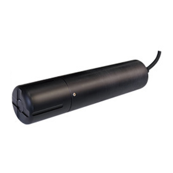
Optical Dissolved Oxygen Sensor
DOS-20
Thank you very much for purchasing Optical Dissolved Oxygen Sensor
DOS-20.
All of this instruction manual must be read before operation of this
Optical Dissolved Oxygen Sensor for safe and proper operation.
This instruction manual should be kept for future reference such as
maintenance.
The instruction manual is also available on the following website.
https://navi.optex.net/manual/05160/?lang=en
Instruction
Manual
Advertisement
Table of Contents

Subscribe to Our Youtube Channel
Related Manuals for Optex DOS-20


Summary of Contents for Optex DOS-20
- Page 1 Optical Dissolved Oxygen Sensor DOS-20 Instruction Manual Thank you very much for purchasing Optical Dissolved Oxygen Sensor DOS-20. All of this instruction manual must be read before operation of this Optical Dissolved Oxygen Sensor for safe and proper operation. This instruction manual should be kept for future reference such as maintenance.
- Page 2 The Contents of Packaging Sensor: 1 Sensor cap (DOS-CP) :1 Calibration container: 1 Instruction manual (this document) If there are any missing or faulty items, please contact our sales representative. Can be connected to SC-U1. Reference...
-
Page 3: Table Of Contents
Table of Contents For Safe Use ................5 Component Name ..............7 Attaching the Sensor Cap ............. 8 Installation ................9 Sensor installation ..............9 Extension of sensor cable ........... 11 Wiring ................... 12 Sensor Setting ..............13 Display item ................ 13 Response time .............. - Page 4 10 Adjustment ................30 Offset adjustment ..............30 Span adjustment ..............32 2-point adjustment .............. 34 Adjustment initialization ............36 Salinity adjustment .............. 37 Altitude adjustment ............. 39 11 Maintenance Setting ............41 Measurement value hold ............. 41 Hold timer ................41 Maintenance timer ..............
-
Page 5: For Safe Use
● Please thoroughly read “For Safe Use” before using this Optical Dissolved Oxygen Sensor properly. ● Because these precautions are related to failure or malfunction, observe the precautions for use without fail. Do not use DOS-20 except for measurement of water quality. " " denotes "Prohibited action", and "... - Page 6 To clean the product, first Use the sensor with 12 to wipe away lightly with a clean 36 VDC. soft cloth damped by diluted Otherwise it may cause fire mild detergent solution and or electric shock. then wipe off moisture with a dry clean soft cloth.
-
Page 7: Component Name
Component Name Detection Protective cover Surface Sensor cap Temperature Measurement sensor area... -
Page 8: Attaching The Sensor Cap
Attaching the Sensor Cap Rotate the protective cover and remove it from the sensor, and then remove the red protective cap. Protective cap Protective cover Caution Store the protective cap for later use. Remove the sensor cap supplied from the storage case. Align the arrows on the sensor cap and the sensor, push the sensor cap straight onto it and then press it into place while... -
Page 9: Installation
Installation Sensor installation Before installation, turn off the power switch of SC-U1 or disconnect the power cable from the supply source and wire the power cable after the installation is complete. " " denotes "Prohibited action", and " " denotes "Required action". The end of the sensor cable is Make sure that air equipped with a female screw... - Page 10 Recommendation ・ An optional attachment (DA-1) for the DO sensor is also available. This is to be used when installed in a location with fast water currents. ・ DO sensor attachment includes items (1) to (4) shown in the following figure.
-
Page 11: Extension Of Sensor Cable
Extension of sensor cable The standard length of the sensor cable is 10 m. To extend the cable, refer to the following. To extend the cable, connection using pull box is recommended. Max. cable length 1200 m (nominal cross-sectional area of 0.2 to 1.25 mm Pull box, etc. -
Page 12: Wiring
Wiring Use this product by connecting to Universal Transmitter SC-U1. For installation and wiring to SC-U1, refer to the "Universal Transmitter SC-U1 Installation Manual". Before wiring, turn off the power switch of SC-U1 or disconnect the power cable from the supply source and wire the power cable after all the other wiring is complete. -
Page 13: Sensor Setting
Sensor Setting The following settings are available from SC-U1. To start sensor setting, press Caution Pressing automatically retains the measurement value. Display item Set measurement items to display as main, 2nd, and 3rd display of SC-U1. Main display 2nd display 3rd display Select an item from the following. -
Page 14: Response Time
Display item Factory default Measurement item setting Item Unit Main Dissolved oxygen con- mg/L display centration Dissolved oxygen % %Sat. % sat saturation Oxygen partial pressure O-Press kPa Temp. display ° C Temperature Temp. display Dissolved oxygen % %Sat. % sat saturation Dissolved oxygen con- mg/L... -
Page 15: 4-20 Ma Setting
4-20 mA Setting Set the 4-20 mA signal output setting from SC-U1. The factory default setting is OFF for 4-20 mA signal output. To set 4-20 mA output setting, press Caution Pressing automatically retains the measurement value. Output item selection Select an item to output by 4-20 mA signal. -
Page 16: Upper/Lower Limit Of Signal Output Range
Upper/lower limit of signal output range For the item by 4-20 mA signal output, set measurement value to output at lower limit (Lo, 4 mA) and upper limit (Hi, 20 mA). 20 mA Signal output 4 mA Measurement Measurement value at 4 mA value at 20 mA For operation, refer to the "Universal Transmitter SC-U1 Operation Manual", "5.3 4-20 mA Setting", "... -
Page 17: Relay Setting
Relay Setting Set the relay output setting from SC-U1. The factory default setting is OFF for relay output. To set the relay setting, press Caution Pressing automatically retains the measurement value. Alarm output setting Set the alarm to be output when the measurement value exceeds a certain value. -
Page 18: Maintenance Output Setting
Maintenance output setting Set a maintenance timer for any cycle (“Maintenance timer” P.42) to notify the user when the set period has elapsed. Use this for notification of sensor maintenance, replacement of consumables, and overhaul timing. Check notifications by the relay output and dedicated cloud server (SC-U1 and GW connected). - Page 19 The channel selection display is displayed. For each relay output channel, the current sensor channel, output item, trigger setting, and active level are displayed. To switch between pages, press Output item Sensor channel Select a relay output channel to set using , and press The setting item selection menu is displayed and the current setting...
-
Page 20: Cleaning Output Setting
Cleaning output setting Set the cleaning device to operate with relay output. For operation, refer to the "Universal Transmitter SC-U1 Operation Manual", "5.4 Relay Setting" and " ◆ Cleaning output setting". Self Checking output setting Set an output when a malfunction such as sensor failure or disconnection occurs. -
Page 21: Calibration
Calibration Perform calibration before using the sensor or after cleaning. Prepare a sensor cap and calibration container. Also, prepare the necessary calibration solution for your calibration needs. To calibrate SC-U1, press ・ Pressing automatically retains the measurement value. ・ Only dissolved oxygen concentration can be calibrated. If the Caution dissolved oxygen concentration is not set in the displayed item, calibration cannot be performed. -
Page 22: 1-Point Calibration: 100% Saturation Calibration
Condensation on the measurement part may affect the measurement value. Wipe off water, if any, from the measurement block before calibration. Press The sensor selection display is displayed. Select a channel connected to DOS-20 using , and press The calibration menu is displayed. Sensor model Measurement item... - Page 23 Select [1-Point Cal.] using , and press Check that the measurement value is stable, and press The calibration starts. When the calibration is complete, a progress bar is displayed and then the calibration result is displayed. When the calibration is complete, check the result. good: The calibration is properly completed.
-
Page 24: 2-Point Calibration: 100% Saturation Calibration And 0-Point Calibration
1-point calibration steps. (Refer to “1-point calibration: 100% saturation calibration” P.22, steps 2 to 4.) Press The sensor selection display is displayed. Select a channel connected to DOS-20 using , and press The calibration menu is displayed. Sensor model... - Page 25 Perform the 1st point calibration. Check that the measurement value is stable, and press The display changes to the 2nd point calibration preparation. A zero standard solution is 100 ml of deionized water into which 5 g or more of sodium sulfite has been added and completely dissolved.
- Page 26 Perform the 2nd point calibration. Check that the measurement value is stable, and press The calibration starts. When the calibration is complete, a progress bar is displayed and then the calibration result is displayed. When the calibration is complete, check the result. good: The calibration is properly completed.
-
Page 27: Optional Density Calibration
Optional density calibration It is possible to immerse the sensor in the solution for which the dissolved oxygen concentration is known and align the display value with this concentration. Item Factory default Setting range [Display] setting Dissolved oxygen 2.00 to 50.00 (by 0.01) 2.00 concentration [DO] Prepare calibration (“Preparation”... - Page 28 Select a channel connected to DOS-20 using , and press The calibration menu is displayed. Sensor model Measurement item Sensor channel Select [Optional Density] using , and press Current measurement value is displayed on the upper area. Enter the density (calibration value) to adjust to in the lower area.
-
Page 29: Initialize Calibration Value
When the calibration is complete, check the result. good: The calibration is properly completed. good E4200 to E4299: Calibration failed. E4200 Try the steps again from 1. Pressing switches to the measurement value display. Initialize calibration value The adjusted values are reset to the factory default setting. For operation, refer to the "Universal Transmitter SC-U1 Operation Manual", "6 Calibration"... -
Page 30: Adjustment
Adjustment Adjust and display the measurement values according to usage. In addition, adjust and display the measurement values according to the environment where used. To adjust, press ・ Pressing automatically retains the measurement value. ・ The dissolved oxygen saturation and oxygen partial pressure cannot be adjusted. - Page 31 to select the item for offset adjustment and press to switch pages. Sensor model Measurement item The adjustment menu is displayed. Sensor channel Select [Offset Adjustment] using , and press Enter the offset value. Select a digit by value by , and press When a value outside the set range is entered, a short beep sounds.
-
Page 32: Span Adjustment
Span adjustment Set the span coefficient for a measurement value. Display value after span Display the measurement value with adjustment span-adjusted to any display value. For 4-20 mA output (“7 4-20 mA Setting” P.15) Measurement and alarm output (“Alarm output setting” P.17), value the adjusted values are applied. - Page 33 Select [Span Adjustment] using , and press Input a span adjustment value. Select a digit by value by , and press When a value outside the set range is entered, a short beep sounds. Pressing simultaneously while entering a value resets the value to the factory default setting.
-
Page 34: 2-Point Adjustment
2-point adjustment Display current values of the 2 points as any adjustment values, respectively. Performing 2-point adjustment changes the offset and span based on the adjusted values. For 4-20 mA output (“7 4-20 mA Setting” P.15) and alarm output (“Alarm output setting”... - Page 35 Select [2-Point Adjustment] using , and press Enter the [Point 1] display, [Point 1] adjusted, [Point 2] display, and [Point 2] adjusted values in this order. Select a digit by and value by , and press . The value is set and the cursor moves to the next item.
-
Page 36: Adjustment Initialization
Adjustment initialization Reset the adjustment value to the factory default value. Press The measurement item selection display is displayed. Select an item to initialize adjustment using , and press to switch pages. Sensor model Measurement item The adjustment menu is displayed. Sensor channel Select [Initialize Adjustment Value] using... -
Page 37: Salinity Adjustment
Salinity adjustment Perform correction for correct measurement of dissolved oxygen density with a salty solution. For solutions of the same water temperature, the saturated dissolved oxygen content (mg/L) decreases as the salt content of the solution increases. To measure the correct dissolved oxygen density, it is necessary to correct the salinity even of solution containing salt. - Page 38 Enter the correction value for the salinity. Select a digit by value by , and press During adjustment a progress bar is displayed. When completed, the display returns to the measurement value display.
-
Page 39: Altitude Adjustment
Altitude adjustment Perform correction for correct measurement and calibration of dissolved oxygen density at high altitude. The saturated dissolved oxygen content is compared against the oxygen content in the surrounding atmosphere. As the altitude increases, the air pressure in the atmosphere is lowered and the saturated dissolved oxygen content becomes smaller. - Page 40 Select [Altitude Adjustment] using , and press Enter an altitude. Select a digit by and value , and press During adjustment a progress bar is displayed. When completed, the display returns to the measurement value display.
-
Page 41: Maintenance Setting
Maintenance Setting Set the maintenance setting from SC-U1. To perform maintenance, press Caution Pressing automatically retains the measurement value. Measurement value hold The latest measurement value is retained (held). This is used for sensor maintenance and cleaning. For operation, refer to the "Universal Transmitter SC-U1 Operation Manual", "8 Maintenance Setting"... -
Page 42: Maintenance Timer
Maintenance timer Set a maintenance timer for any cycle to notify the user when the set period has elapsed. This is used for notification of sensor maintenance, replacement of consumables, and overhaul timing. Check notifications by the relay output (“Maintenance output setting” P.18) and the dedicated cloud server (SC-U1 and GW connected). -
Page 43: Sensor Cap Replacement Timer
Sensor cap replacement timer Set a replacement period of the sensor cap. Perform notification using a relay output when the set period has elapsed (Refer to "Sensor cap output setting" P.18). "MAINT" is displayed on the measurement value display for the sensor for which the sensor cap replacement notification has been issued. -
Page 44: Sensor Cap Replacement Timer Setting
Perform the following steps to shorten the sensor cap replacement timer according to the measurement target. Press The measurement item selection display is displayed. Select [DO DOS-20] using , and press Sensor cap replacement timer setting must be set for each sensor. The set- ting is not availble if [All] is selected. - Page 45 Select [Timer Setting] using , and press Select a digit by value by , and press The entered number of days is fixed and the display returns to the maintenance menu. To reset the elapsed days and set the days for the timer, select [Timer Clear] using , and press ・...
-
Page 46: Cleaning
While cleaning the measurement value of the target sensor is retained (held). Press The sensor selection display is displayed. Select [DO DOS-20] using , and press By selecting [ALL], all of the connected sensors can be selected. -
Page 47: Cleaning Interval (Relay)
Select [Manual Cleaning] using , and press The cleaning device is activated and the display returns to the measurement value display. The sensor under cleaning shows "CLEAN" on the measurement value display. In addition, "C" is displayed in the sensor selection display. Cleaning interval (relay) Set the time interval between cleaning actions. -
Page 48: Cleaning Activation
Cleaning activation Set the time period for cleaning. Select an item from the following. For operation, refer to the "Universal Transmitter SC-U1 Operation Manual", "9 Cleaning" and " ◆ Cleaning Activation". Factory Item Setting range default setting Cleaning Activation 10 to 120 seconds (by 10 seconds) 30 seconds Post-cleaning standby Set the standby time after cleaning. -
Page 49: Troubleshooting
Troubleshooting Error code list The following table describes error codes, causes and actions. If you find any problem other than the error codes, refer to “When in trouble” in the "Universal Transmitter SC-U1 Operation Manual". When the normal condition is not recovered after the countermeasure is taken, when any problem other than these occurs, or when requesting repairs, check the model and the serial No. - Page 50 Error code and details Cause Action E3600 to E3699 The sensor cable Make sure that the cable is Sensor error is broken. not damaged. If any damage is found, contact the dealer. The sensor cable Turn off power of the trans- is not properly mitter, check the wiring, and wired.
-
Page 51: Maintenance
Maintenance ・ To clean the sensor, lightly wipe with a clean, soft cloth and water diluted with a mild detergent, and then wipe with a dry, Caution soft cloth. ・ Do not wipe the sensor with organic solvent such as benzine. Maintenance (monthly) Perform the following operations every month. -
Page 52: Specifications
Specifications Name Optical Dissolved Oxygen Sensor Model DOS-20 Measurement Dissolved oxygen concentration (mg/L) Temperature ( ° C) item Dissolved oxygen % saturation (%) Oxygen partial pressure (kPa) Measurement Dissolved oxygen concentration: 0.00 - 50.00 mg/L (0.01 mg/L) Temperature: 0.0 - 50.0 ° C (0.1 ° C) - Page 53 Sensor cable 10 m length Sensor cap Every year after sensor installation (guideline) replacement cycle Sensor cap 2 years after manufactured date (when stored in the storage period specified container) Storage temperature: 1 to 60 ° C Option Transmitter (SC-U1) DO Sensor Attachment (DA-1) DO Sensor Adapter (DA-1AP) Replacement Sensor Cap (DOS-CP)
-
Page 54: External Dimensions
External Dimensions 1¼-11½ NPT Female Screw Ø48 (mm) - Page 55 Saturated Dissolved Oxygen Content at Each Temperature (In the case of 1 hPa and salinity level of 0 PSU) Saturated Saturated Saturated Saturated Dissolved Tem- Dissolved Tem- Dissolved Tem- Dissolved Tem- perature Oxygen perature Oxygen perature Oxygen perature Oxygen (°C) Content (°C) Content...
- Page 56 Whole document of the DOC can be referenced in the following website ; www.optex.net OPTEX CO., LTD. 5-8-12, Ogoto, Otsu, Shiga, 520-0101 Japan el.+81-77-579-8680 Fax.+81-77-579-8199 https://www.optex.co.jp/e/products/environmental-sensor/ 2021.11 59-2960-1...
Need help?
Do you have a question about the DOS-20 and is the answer not in the manual?
Questions and answers