Table of Contents
Advertisement
Quick Links
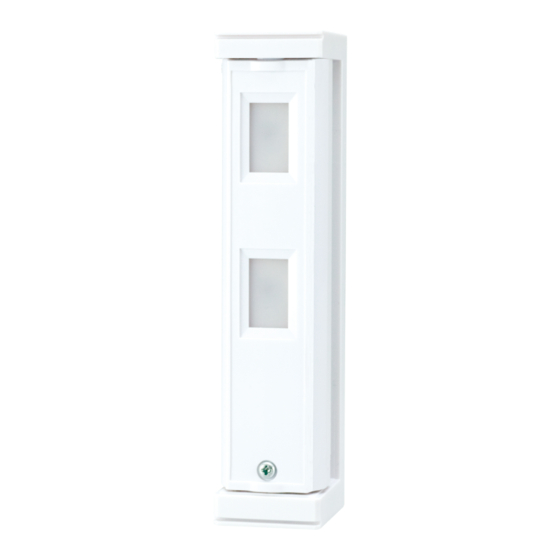
Compact outdoor
Compact outdoor
detector
detector
fit series
fit series
• Compact design
• 190° adjustable bracket
• Intelligent AND logic
CONTENTS
1-1 BEFORE INSTALLATION ...................................... 1
1-2 PARTS IDENTIFICATION ...................................... 2
1-3 DETECTION AREA ................................................ 2
2-1 INSTALLATION ...................................................... 3
3-1 WALK TEST ........................................................... 5
4-1 LED ........................................................................ 5
1
INTRODUCTION
1-1
BEFORE INSTALLATION
Failure to follow the instructions provided with this indication and improper handling may cause
Warning
death or serious injury.
Failure to follow the instructions provided with this indication and improper handling may cause
Caution
injury and/or property damage.
The check
mark indicates recommendation.
Warning
Do not remove the PCB.
Keep the detector parallel to the ground.
WIRED MODEL
• Digital anti-masking (AM model)
• Wall tamper (option)
The nix
Caution
Do not touch the PCB except for the
DIP switch.
ON
1
2
3
4
Tilt
INSTALLATION INSTRUCTIONS
FTN-ST
Standard model with 2 PIRs
FTN-AM
FTN-ST with anti-masking
4-2 ALARM OUTPUT ................................................... 5
4-3 PIR SENSITIVITY .................................................. 5
4-4 ANTI-MASKING...................................................... 6
5-1 WALL TAMPER (OPTION) CONNECTION ........... 6
5-2 EXAMPLE OF EOL WIRING .................................. 7
5-3 LED LIGHT PATTERN ........................................... 7
6-1 SPECIFICATIONS.................................................. 8
6-2 DIMENSIONS......................................................... 8
sign indicates prohibition.
Consider the direction of the intruder,
for the setting of the detection area.
EN-1
No.59-2263-1
Caution
Mounting height.
0.8 to 1.2 m
(2.6 to 3.9 ft.)
Parallel
Advertisement
Table of Contents

Related Manuals for Optex FIT Series


Summary of Contents for Optex FIT Series
- Page 1 No.59-2263-1 INSTALLATION INSTRUCTIONS Compact outdoor Compact outdoor detector detector fit series fit series FTN-ST Standard model with 2 PIRs WIRED MODEL FTN-AM FTN-ST with anti-masking • Compact design • Digital anti-masking (AM model) • 190° adjustable bracket • Wall tamper (option) •...
- Page 2 Install the detector in a place where it is free from false alarm factors. For example: • Heat source • Objects moving in the wind • Sunlight and reflection PARTS IDENTIFICATION Bracket Main unit Screw kit Screw (3 × 20 mm) Main unit cover Lens -Optional accessories...
- Page 3 INSTALLATION INSTALLATION Open the main unit cover. Remove the fixture. Hold the top of the bracket lifted and remove the main unit. Bracket Main unit Fixture Pull the wire through the main unit. Put the wire extending from the wall through the Lift the top of the bracket slightly and mount the main wiring hole in the bottom of the bracket, and unit to the bracket.
- Page 4 Determine the horizontal detection angle Determine the detection length. (2 m or 5 m) and attach the fixture. Note>> • To make adjustments, remove the fixture. Note>> • Check that the fixture and bracket engage correctly. If 2 m is required, rotate the lower lens 180 degrees.
- Page 5 WALK TEST WALK TEST Set DIP switch 1 (LED) to “ON”. Check that LED lights for 2 seconds when the intended object is detected. DIP switch Detected Not detected Note>> • The switch is set to “ON” by factory default. If the LED does not need to be turned on at all times, set the DIP switch 1 (LED) to “OFF”.
- Page 6 FTN-ST ANTI-MASKING DIP switch 4 FTN-AM Position Function ANTI-MASKING ON (Factory default) ANTI-MASKING OFF -ANTI-MASKING function When masking condition continues more than 3 minutes, TROUBLE will be generated. TROUBLE is generated after 20 seconds under the anti-masking test mode. Please close the main unit cover before turning on the power supply. “Teaching mode”...
- Page 7 EXAMPLE OF EOL WIRING Since the alarm and trouble outputs share the COM terminal, the wire connection should be made for the fit series detector according to the following diagram. -Double EOL Alarm relay Trouble relay Tamper Positive (+) Negative (-) Alarm Trouble (N.C.) Tamper (N.C.) Tamper (N.C.)
- Page 8 OPTEX SECURITY Sp.z o.o. (Poland) OPTEX (DONGGUAN) CO.,LTD. URL: http://www.optex.net/br/es/sec URL: http://www.optex.com.pl SHANGHAI OFFICE (China) URL: http://www.optexchina.com OPTEX (EUROPE) LTD. / EMEA HQ (U.K.) OPTEX PINNACLE INDIA, PVT., LTD. (India) URL: http://www.optex-europe.com URL: http://www.optex.net/in/en/sec OPTEX (Thailand) CO., LTD. (Thailand) URL: http://www.optex.net/th/th OPTEX TECHNOLOGIES B.V.(The Netherlands)
Need help?
Do you have a question about the FIT Series and is the answer not in the manual?
Questions and answers