
Subscribe to Our Youtube Channel
Related Manuals for Kellfri 26-GAATV360


Summary of Contents for Kellfri 26-GAATV360
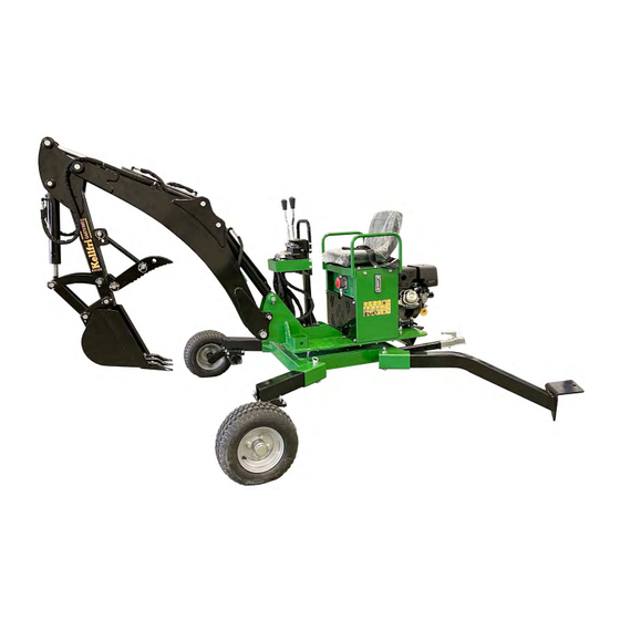
- Page 1 26-GAATV360 BACKHOE DIGGER 360 FOR ATVS Carefully read the operating instructions before using the product! Operating instructions translated from Swedish...
- Page 2 Deviation form Warranty terms and conditions Kellfri designs and supplies efficient, affordable machinery and components for forestry, agriculture, construction and gardening in Sweden, the rest of the Nordic region and Europe. Please note that the information in this document is general and may not pertain to your particular machine.
- Page 3 INTRODUCTION Thank you for choosing a product from Kellfri AB. Compliance with the safety instructions, operating manual and sound common sense will guarantee many years of enjoyment using the product. Kellfri’s equipment and products are aimed at self-employed farmers, horse enthusiasts and other country dwellers with stringent performance demands.
- Page 4 Unauthorised modifications and/or accessories may cause life-threatening injuries or death to users and others. Kellfri is not liable for any modifications, changes or rebuilds carried out by customers. Where the machine is used professionally, employers are responsible for ensuring that users of the machine have theoretical and practical knowledge of the machine and that work is performed in a safe manner.
- Page 5 SURROUNDINGS Check that the work area is free from bystanders and objects before hitching or using the equipment. Otherwise, there is a risk of serious injury. Be extra careful if there are children in the vicinity of the area where the equipment or product is used or stored. Check that there are no low-hanging electrical cables within the work area.
- Page 6 Only those who understand the safety instructions and the operating manual may use the equipment or product. Exercise caution and care when working with the equipment or product, and only use it as described in the instruction manual. There is a risk of crushing when working with equipment that has moving parts. Exercise caution when working with equipment with hydraulic hoses, as oil under pressure can penetrate the skin.
- Page 7 MAINTENANCE AND SERVICE • Before maintenance, make sure that the engine is switched off and has cooled down completely. • Make sure that the digger is stable and cannot tip over while maintenance or service work is being performed. • Replace damaged or worn parts immediately to reduce the risk of injuries.
- Page 8 MACHINERY/EQUIPMENT CONNECTED TO HYDRAULICS Be careful when you connect your machine or equipment to a hydraulic hose. DANGER! Pressurised oil and fuel leaks can penetrate skin and cause serious injuries. Do not use your hands to locate leaks. Use a piece of paper or cardboard to look for leaks. •...
- Page 9 Never fill the machine with fuel when it is still hot. Wait a few minutes until it has cooled down before you fill the machine with fuel. Kellfri AB has a policy of continuous product development and therefore reserves the right to make modifications, e.g. to the design and appearance of the product, without prior notice.
- Page 10 WARNING DECALS Make sure warning decals are always visible and clean them when necessary. Do not use a high-pressure washer directly on the warning decal. If a part with a decal is replaced, or the decal becomes worn or in any other way unusable, order a new set of decals. SYMBOL EXPLANATION Read the operating manual! Before carrying out work.
- Page 11 CHEMICALS To maximise the service life of a product/equipment, maintenance - and not least preventive maintenance - is important, and this is largely what greases and oils do. Carefully read the operating manuals for your new products or equipment to ensure correct maintenance and service life and that the warranty remains valid! Lubricating greases First aid measures.
- Page 12 PARTS 26-GAATV360 • Main frame incl. boom • Bucket • Grapple attachment • Wheel carrier and wheel, x 2 • Stabiliser, x 2 • Tow bar and tow bar ball hitch (locking pin + ring pin x 2) • Locking pin + ring pin, x 4 •...
- Page 13 ASSEMBLY Because of the backhoe digger’s weight, it is recommended that unpacking and assembly are carried out by two people. If possible, it is a good idea to use a lifting device to facilitate assembly. Fitting the boom Raise the boom and turn it around to its position so that the pin can be fitted. Make sure that the hole in the pin matches the hole...
- Page 14 Placement of transport pin. Bear in mind that the hoses must be placed under the transport pin. Fit the lower pin 1), lock in place with screw. Fit transport pin 2), lock in place with R-pin. Table of Contents...
- Page 15 Screw handles onto the levers. Fitting the valve block • Remove the plastic covers. • Start screwing the hoses onto the bottom row. • NOTE: Match the colour, i.e. the colour of the hose must be the same as the hose bracket. •...
- Page 16 Fitting the wheel carriers (right and left) Lock in place with a safety cotter pin and secure with Ring pin. Bear in mind! Removing the tow bar DIRECTION OF TRAVEL Tow bar Wheel Fitting the stabilisers (right and left) Lock in place using safety cotter pin and secure with Ring pin.
- Page 17 Grapple attachment Fit grapple attachment in brackets above the bucket. The holes allow you to adjust the size of the opening you want when in use. For example, if you need to lift up stones of different sizes. Limitation valve. Function.
- Page 18 Drain plug. Topping up the engine oil approx. 1.1 litre (10W40 or 15W40) Oil can be added in two places. One of the filling points has a dipstick. • Bear in mind: Before draining, place a collection vessel under the backhoe digger. •...
- Page 19 1.) Start the engine and allow it to idle. NOTE: Don’t forget to remove the transport locking device! 2.) Pull one of the lever arms back and forth to remove air from the system. While moving, look at the transparent hose on the right-hand side under the control levers. If there is a flow of bubbles, this is normal.
- Page 20 FROM TRANSPORT MODE TO EXCAVATION MODE 1 Remove the transport locking devices for the lifting boom and rotation, see page 20. 2 Start the engine on the backhoe digger according to the instructions in the manual. 3. Now rotate the machine to the right and left respectively, using the digger arm to lift/tilt the backhoe digger .
- Page 21 Transport locking device Transport locking device TRANSPORT MODE Fit pins (transport locking device) before transport. Important! Place the stabilisers in in an upright position during transport. Lock securely with pin. Table of Contents...
- Page 22 BEFORE YOU START DIGGING Before digging, it is a good idea to plan the work first. The operator should inspect the work area and check for possible hazards. The operator should have a complete understanding of the work to be performed. After familiarising yourself with the work area, it’s time to plan the actual digging.
- Page 23 OPERATION AND DRIVING Important! Never drive the towing vehicle/ATV while someone is sitting on the digger! The backhoe digger has 2 control levers (see figure below). Read the safety precautions in the operating instructions before using the machine. Remember: Left and Right are determined by the operator’s seated position on the digger and the steering of the bucket.
- Page 24 BASIC EXCAVATION TECHNIQUES When you start digging, always make the first cuts as thoroughly as possible and make sure you follow the contour. The purpose of this is to minimise damage to the ground and the bucket. The first cuts are also important, as they will serve as a template for the remaining cuts.
- Page 25 SERVICE INTERVAL MEASURE Tyres • Before each use • Check the pressure - see info on the sidewalls of the tyres. Do not exceed the maximum pressure! Hoses • After each use • Check for damage and leaks. Replace damaged or broken hoses before use. Hydraulic couplings •...
- Page 26 GREASE POINTS Table of Contents...
- Page 27 GREASE POINTS, contd. Turntable bearings. Grease point. Remove grey plug and top up. Refit the plug after topping up. Table of Contents...
- Page 28 Version 1:1 ITEM NO. SPARE PART NO. DESIGNATION QUANTITY Large/small swing arm Engine unit R26-GAATV2.001 Wheel carrier, left/right Frame Table of Contents...
- Page 29 Version 1:1 ITEM NO. SPARE PART NO. DESIGNATION QUANTITY Hex head bolt M8x25 R26-GAATV2.039 Hydraulic pump R26-GAATV2.038 Claw coupling tube R26-GAATV2.024 Pin, rear bucket cylinder R26-GAATV2.043 Claw coupling, engine shaft R26-GAATV2.041 Claw coupling, engine cover JF420 Engine R26-GAATV2.042 Sleeve, engine shaft claw coupling Spring washer 6 Flat washer 6 Hex head bolt M6x12...
-
Page 30: R26-Gaatv2.012
Version 1:1 ITEM NO. SPARE PART NO. DESIGNATION QUANTITY R26-GAATV2.009 Boom R26-GAATV2.010 Articulated boom R26-GAATV2.011 Articulated joint, straight R26-GAATV2.012 Articulated boom cylinder R26-GAATV2.013 Cylinder bucket R26-GAATV2.014 Articulated joint, curved R26-GAATV2.015 Bucket Table of Contents... - Page 31 ITEM NO. SPARE PART NO. DESIGNATION QUANTITY R26-GAATV2.016 Cylinder boom R26-GAATV2.017 Pin lower bracket boom R26-GAATV2.019 Pin boom joint R26-GAATV2.020 Pin, front boom cylinder by piston rod R26-GAATV2.021 Pin, rear articulated joint cylinder R26-GAATV2.022 Pin, front articulated joint cylinder by piston rod R26-GAATV2.023 Pin Articulated boom joint with Boom R26-GAATV2.024...
- Page 32 Version 1:1 Table of Contents...
-
Page 33: R26-Gaatv2.035
ITEM NO. SPARE PART NO. DESIGNATION QUANTITY Hex head bolt M10x70 Washer 10x2.5 Seat plate, left Hex head bolt M8x16 Spring washer 8 Flat washer 8 Protective guard, valve Return coupling for draining Safety cotter pin Draw pin Support rest Hex head screw M8x25 Lock nut M8 R26-GAATV2.035... - Page 34 Version 1:1 Table of Contents...
- Page 35 ITEM NO. SPARE PART NO. DESIGNATION QUANTITY Hydraulic air filter Fuel tank R26-GAATV2.045 Seat Bottom plate Locking pin Ф8 Stabiliser Locking pin Lock nut M10 Washer 10 R26-GAATV2.046 Rubber engine mount Ball coupling Hex head bolt M12x70 Lock nut M12 Flat washer 12 Rotatable support Main frame...
-
Page 36: Table Of Contents
Version 1:1 ITEM NO. SPARE PART NO. DESIGNATION QUANTITY Return coupling for draining R26-GAATV2.012 Articulated boom cylinder R26-GAATV2.013 Cylinder bucket R26-GAATV2.035 Valve block R26-GAATV2.039 Hydraulic pump R26-GAATV2.059 Pre-filter R26-GAATV2.060 Hydraulic tank connection Hose clamp d32 Table of Contents... -
Page 37: Quantity
contd. ITEM NO. SPARE PART NO. DESIGNATION QUANTITY Rubber tube R26-GAATV2.064 Pump adapter R26-GAATV2.016 Cylinder boom R26-GAATV2.037 Gasket, hydraulic tank connection R26-GAATV2.067 Hydraulic coupling R26-GAATV2.068 Hydraulic coupling Restrictor valve Fuel tank R26-GAATV2.040 Sight glass, hydraulic tank Hydraulic air filter Return oil filter element Hydraulic motor Motor joint Flat washer 6... - Page 38 Version 1:1 ITEM NO. SPARE PART NO. DESIGNATION R26-GAATV2.051 Wheel bolt kit R26-GAATV2.052 Tyre with rim R26-GAATV2.053 Wheel carrier, left R26-GAATV2.054 Wheel carrier, right Table of Contents...
- Page 39 Total length 4410 mm Width of support 1986 mm Width of main frame 969 mm Minimum width in transport mode 1863 mm Minimum length in transport mode 2940 mm Max. height 2502 mm Table of Contents...
- Page 40 Max. excavation depth 1727 mm Reach 2359 mm Max. loading height 2502 mm Bucket rotation 45° Horizontal angle of rotation 360° Vertical angle of rotation 124° Table of Contents...
- Page 41 Table of Contents...
- Page 42 Hydraulic diagram for swing/rotation (seat) Table of Contents...
- Page 43 DEVIATION FORM We are grateful for your help in pointing out any defects in the product supplied to you by Kellfri. Before making a claim, read Kellfri’s general purchase terms and conditions in our catalogue or on our website www.kellfri.co.uk, and in the operating manual if supplied.
- Page 44 You are always welcome to give feedback or ask us about our equipment and products. Kellfri AB has a policy of continuous product development and therefore reserves the right to make modifications, e.g. to the design and appearance of the product, without prior notice.
Need help?
Do you have a question about the 26-GAATV360 and is the answer not in the manual?
Questions and answers