
Subscribe to Our Youtube Channel
Related Manuals for Kellfri 27-SF20


Summary of Contents for Kellfri 27-SF20
- Page 1 27-SF20 STUMP GRINDER PLEASE READ ALL INSTRUCTIONS BEFORE USING THE PRODUCT!! TRANSLATED FROM THE ORIGINAL...
-
Page 2: Table Of Contents
Table of content Introduction Product details Basic safety instructions Product safety instructions Instructions for emergency situations Personal protection Surroundings Warning labels Steps to take before use Fueling Machine information: handle bar, throttle, brake Starting the engine Operation Stage 1 and 2 Normal shutdown Cutting Blade Assy. -
Page 3: Introduction
INTRODUCTION Thank you for choosing a product from Kellfri AB. By following general safety information, operating instructions and common sense, you will have many years of enjoyable use of the product. Kellfris equipment and products are aimed to be use by active farmers with high demands on functionality. -
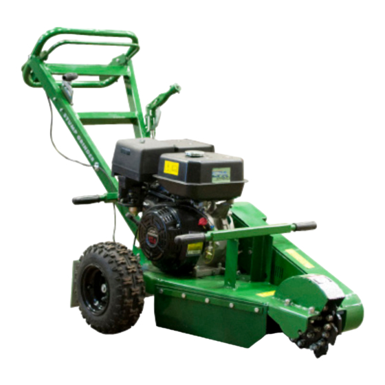
Page 4: Product Details
TECHNICAL DATA 27-SF20 Model JF390 Motor 4-stroke engine, tilt, single cylinder, air cooled Max Power 13 hp Cylinder diameter and stroke 88 x 64 mm Capacity 389 ml Compression 8.0:1 Max torques 26.4Nm von 2500 rpm Ignition system Non-contact transistorized ignition(T.C.I) -
Page 5: Basic Safety Instructions
Kellfri AB, Munkatorpsgatan 6, 532 37 SKARA Sweden. Tel.: +46 (0)511 242 50 (Pls. contact the retailer) https://www.kellfri.co.uk/ Do not use the equipment or product if you feel ill, tired or are under the influence of alcohol. -
Page 6: Instructions For Emergency Situations
INSTRUCTION FOR EMERGENCIES In case of an emergency please dial 112. Keep cell phone or emergency phone available specially when working alone. First aid kit and fire extinguishers must be kept easily accesable during all work, maintenance and service. PERSONAL PROTECTIVE EQUIPMENT Always use suitable protection equipment. -
Page 7: Warning Labels
WARNING LABELS Make sure that the warning labels are always visible, clean the warning labels if necessary. Do not wash with high pressure washer directly on the warning label. If any part of the decal is worn or label becomes frayed or otherwise unreadable, order new decals. SYMBOL Explanation Danger zone 5 m... -
Page 8: Steps To Take Before Use
BEFORE USE Read the instruction manual carefully. Be sure that you understand the safety information, in- struction manual and warning labels. Use common sense when using and use the appropriate personal protective equipment Always check the performance of the machine combination to be used. -
Page 9: Use
USE / OPERATION Only people who understand the safety information and instructions in this manual may op- erated the equipment. Be alert and careful when working with the machine and only use the tool or product in the manner described in this manual. When working with equipment that has moving parts, there is always the risk of injury. -
Page 10: Machine Information: Handle Bar, Throttle, Brake
SAFETY PRESENCE GRIP BAR The bar must be held against the handle for the engine to run. If you release the grip, the ignition system short-circuits and the en- gine stops. DO NOT BIND THE BAR TO THE HANDLE. IT IS THERE FOR YOUR SAFETY. Warning! GRIP BAR THROTTLE... -
Page 11: Starting The Engine
STARTING THE ENGINE Always follow the recommended service and maintenance, written under the Mainte- nance and Service. Make sure there is enough fuel in the tank Fuel valve: Open the fuel valve. Place the lever all the way to the right. (fig.1) Choke control: When starting the engine warm, the lever should be in the right posi- tion;... - Page 12 Operation Stage 1 Place stump machine into position with cutting blade near the front-top edge of stump. Set brake to lock position. Set throttle to (START ) DISENGAGE position. Start engine. Allow engine to warm up at idle for two minutes. Move throttle up to the ENGAGE position (this will engage the cutting blade rotation).
-
Page 13: Normal Shutdown
NORMAL SHUTDOWN Disengage cutter Throttle wheel - START position Set the throttle to SLOW/DISENGAGE. If the engine has been running full out, let it run easily for about 30 seconds to one minute at low speed. Engage cutter wheel DO NOT let front of unit touch ground until you are sure cutting wheel has stopped turning WARNING! A rotating cutting blade is very DANGEROUS! Stay at the operating position and be sure that... -
Page 14: Cutting Blade
CUTTING BLADE Among the most critical elements of the Stump Machine is the cutting blade. It is also the most subject to damage and wear. In the course of cutting stumps it not only makes contact with the wood, but also encounters numerous assortments of abrasives and objects in the stump’s environment, such as dirt, stones, and occasionally a large rock or buried scrap. -
Page 15: Assy. Throttle Control Handle
Assemble the Throttle Control Handle • Make sure the throttle lever should be at minimum position on engine before start assembly. THROTTLE LEVER WINGNUT • Then, fix the Throttle Control Handle Ass’y to the Lifting Handle. Make sure the top of handle bar should touch the Butterfly Nut, and the bottom of the handle bar should touch the pressure plate. -
Page 16: Maintenance And Service
MAINTENANCE AND SERVICE Make sure the tool stands stable and not likely to tip over during maintenance and service. Re- place damaged and worn parts immediately to reduce the risk of injury. Perform maintenance, servicing and inspections as recommended. Use only parts with equivalent performance to reduce the risk of damage and failure. -
Page 17: Transport And Storage
TRANSPORTATION AND STORAGE Make sure that the area is clear of people, children and objects before transportation. Always be extra careful during transport and movement. Ensure that the product is well secured and that existing transport safety devices are mounted. Always place the load as low as possible. Respect the danger zones even during transport and movement. -
Page 18: Engine Oil Change
ENGINE OIL CHANGE • When changing oil, be sure to use approved containers for oil. Old oil must be disposed properly in recycling center. Contact your municipality for more information. • Ensure that the machine can not tip over. • Pull out the dipstick. -
Page 19: Troubleshooting
SYMPTOM CAUSE ACTION The engine don’t start • Fuel valve closed. • Open the fuel valve. • Fuel tank is empty • Check and fill up fuel • Open choke valve • Close choke valve • Engine switch in OFF position. •... -
Page 20: Inspection: Sparkplug
INSPECTION, CLEANING AND REPLACING THE SPARK PLUG 1. Disconnect the spark plug wire and remove the spark plug, use a spark plug wrench. 2. Clean the spark plug and measure the distance between the spark gap (distance between electrodes). The correct distance is between 0.7mm-0.8mm 0.7 mm - 0.8 mm 3. - Page 21 IMPORTANT! When replacing a belt or checking the belts before first operation of the machine: Make sure that the pulleys are aligned with each other. It is important that the belts are straight to prevent damage and wear to the centrifugal clutch and drive shaft.
- Page 23 CHASSIS AND ENGINE ASSY. Description Description Frame Axle Sleeve Spring Washer Ø8 "Hexagonal Screw M8x50" Lock Nut Nylon M8 9J Joined Narrow V-Belt Engine Outer Belt Guard Lock Nut Nylon M10 Flat Key 6x50 Spring Washer Ø10 "Hexagon Screw M10x16" Flat Washer Ø10 Pulley Locker Axle...
-
Page 24: Handle Ass
HANDLE ASSY. - Page 25 Description Description Chassis Assy. "Cross Head Screw M5x12" Spring Washer Ø8 Pressure Plate Lock Nut Nylon M8 Spring Washer Ø5 Handle Cover Lock Nut Nylon M5 Lock Nut Nylon M12 Pressure Plate Spring Washer Ø12 Step Bolt M6x25 Flat Washer Ø8 "External Lock Washer Ø8"...
-
Page 26: Cutting Head
CUTTING HEAD TORQUE 81 Nm Description Lock Nut Nylon M10 Spring Washer Ø10 Flat Washer Ø10 Bearing UCP205 Blade Fastness Set "hexagon socket screw M6x8" Hex Bolt M10x45 Shaft With Key Trencher Blade A Shaft Flange HEX BOLT M10X35 Half Plate Trencher Blade B Trencher Blade C... -
Page 27: Wheel Assy
WHEEL ASSY. Description Description Chassis Assy. Axle Fastness Set Axle Wheel Assy. Hex Bolt M8x20 Deep Groove Ball Bearing 6202 Cotter Ø2 x16 Bearing Block A Assy. Brake Cable Assy. Brake Mounting Plate A Assy, Large Washer Ø6 Brake Bolt Lock Nut Nylon M6 Hex Nut M12 Spring Washer Ø6... -
Page 28: Break Assy
BREAK ASSY. Description Flat Washer Ø8 Lock Nut Nylon M6 Spring Washer Ø6 "Hexagonal Socket Head Cap Screw M6x50" Brake Mounting Plate Assy, Brake Spring A "Brake Mounting Plate A Assy," Bush Large Washer Ø8 Tie Plate Adjusting Plate Flat Washer Ø6 Brake Spring B Split Washer Ø6-E... -
Page 29: Chassis And Flap Assy
CHASSIS AND FLAPS ASSY. Description Hex Bolt M8x25 Rear Flap Support Rear Flap Chassis Assy. Spring Washer Ø8 Lock Nut Nylon M8 Side Flap Support Side Flap Side A Flap Side A Flap Support Side B Flap Side B Flap Support... -
Page 30: Break Handle Assy
BREAK HANDLE ASSY. Description Description Flat Washer Ø8 Bush Handle Bush Tie Plate A "Lock Washer Ø6" Tie Bar Lock Nut Nylon M6 Tie Bar A Spring Washer Ø6 Bolt Split Washer Ø6-E Handle Assy. Tie Bar “Spring Lock Washers Ø10" Adjusting Hook Assy. -
Page 31: Complaint Form
Complaint form We are grateful for your help pointing out any inaccuracies in the Kellfri product delivered to you. Before making a complaint read Kellfris general warranty and sales conditions in our catalog as well as the enclosed User’s manual that comes with the machine. -
Page 32: Warranty Terms & Eg-Declaration
Other equipment must meet the hardware requirements of the Directive. Tina Baudtler, VD Skara 2013-07-23 Kellfri AB is constantly working on further developing their products and therefore reservesthe right to modify, among other things the design and appearance without notice. Kellfri AB...
Need help?
Do you have a question about the 27-SF20 and is the answer not in the manual?
Questions and answers