
Related Manuals for Kellfri 26-GAATV2


Summary of Contents for Kellfri 26-GAATV2
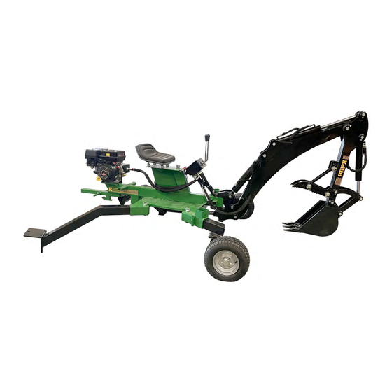
- Page 1 26-GAATV2 BACKHOE DIGGER FOR ATVS Carefully read the operating instructions before using the product! Operating instructions translated from Swedish...
- Page 2 Deviation form Warranty terms and conditions Kellfri designs and supplies efficient, affordable machinery and components for forestry, agriculture, construction and gardening in Sweden, the rest of the Nordic region and Europe. We recommend that you always read and follow the safety instructions and the instructions in the machine’s operating manual.
-
Page 3: Product Information
INTRODUCTION Thank you for choosing a product from Kellfri AB. Compliance with the safety instructions, operating manual and sound common sense will guarantee many years of enjoyment using the product. Kellfri’s equipment and products are aimed at self-employed farmers, horse enthusiasts and other country-dwellers who have stringent performance demands. -
Page 4: Safety Instructions
Unauthorised modifications and/or accessories may cause life-threatening injuries or death to users and others. Kellfri is not liable for any modifications, changes or rebuilds carried out by customers. Where the machine is used professionally, employers are responsible for ensuring that users of the machine have theoretical and practical knowledge of the machine and that work is performed in a safe manner. -
Page 5: Before Use
SURROUNDINGS Check that the work area is free from bystanders and objects before hitching or using the equipment. Otherwise, there is a risk of serious injury. Be extra careful if there are children in the vicinity of the area where the equipment or product is used or stored. Check that there are no low-hanging electrical cables within the work area. -
Page 6: After Use
Only those who understand the safety instructions and the operating manual may use the equipment or product. Exercise caution and care when working with the equipment or product, and only use it as described in the instruction manual. There is a risk of crushing when working with equipment that has moving parts. Exercise caution when working with equipment with hydraulic hoses, as oil under pressure can penetrate the skin. -
Page 7: Maintenance And Service
MAINTENANCE AND SERVICE • Make sure that the equipment is stable and cannot tip over when carrying out maintenance and service work. • Replace damaged or worn parts immediately to reduce the risk of injuries. • Carry out maintenance, service and checks in line with recommendations. •... - Page 8 MACHINERY/EQUIPMENT CONNECTED TO HYDRAULICS Be careful when you connect your machine or equipment to a hydraulic hose. DANGER! Pressurised oil and fuel leaks can penetrate skin and cause serious injuries. Do not use your hands to locate leaks. Use a piece of paper or cardboard to look for leaks. •...
-
Page 9: Product Safety Instructions
PRODUCT SAFETY INSTRUCTIONS • Always read the instruction manual carefully before using the backhoe digger. • Never put your hands or feet under the machine without first stopping the equipment and turning off the engine. • Never leave the equipment with the engine running. Switch off the engine when you leave the equipment –... -
Page 10: Warning Decals
WARNING DECALS Make sure warning decals are always visible and clean them when necessary. Do not use a high-pressure washer directly on the warning decal. If a part with a decal is replaced, or the decal becomes worn or in any other way unusable, order a new set of decals. SYMBOL EXPLANATION Read the operating manual! Before carrying out work. - Page 11 CHEMICALS To maximise the service life of a product/equipment, maintenance - and not least preventive maintenance - is important, and this is largely what greases and oils do. Carefully read the operating manuals for your new products or equipment to ensure correct maintenance and service life and that the warranty remains valid! Lubricating greases First aid measures.
- Page 12 PARTS 26-GAATV2 Main frame Boom Tow bar ball hitch Swing cylinder Bucket Wheel carrier and wheel, x 2 Grapple attachment Chain, x 2 Stabiliser, x 2 Valve block Bracket for swing cylinder Bracket for boom Table of Contents...
- Page 13 ASSEMBLY Because of the backhoe digger’s weight, it is recommended that unpacking and assembly are carried out by two people. If possible, it is a good idea to use a lifting device to facilitate assembly. 1 Fitting the wheel carriers (right and left) Lock in place using safety cotter pin and secure with Ring pin.
- Page 14 3. Bracket for swing cylinder. Unscrew bolts on bracket (A). Fit the bracket from below (B). Tighten the bolts from below first, and then the bolts on top (C). 4. Fitting the bracket for the boom Loosen the cotter pin, lift up the pin. Place bracket for boom on main frame.
- Page 15 5. Fitting the boom Raise the boom to fit the pin. Loosen the screws and then remove the pin. (Use tool and rubber mallet). Position the boom and reinsert the pin, lock in place using the screws. 6. Fitting the pin a.
- Page 16 7. Fitting the bucket Raise the boom so that the bucket can be fitted. Lock with bolt. Grapple attachment Fit the grapple attachment in the brackets above the bucket. The holes allow you to adjust the size of the opening you want when in use.
- Page 17 8. Fitting the valve block Fit the levers. Cotter pin Fitting the levers Remove the cotter pin. Place handles (Note: right and left) as shown with the “ball- shaped” side facing up and the pin through the pre-drilled hole. Replace the cotter pin to lock the lever in place.
- Page 18 9. Fitting the swing cylinder Remove the ring pin on the cylinder. Fit the right-hand side of the swing cylinder onto the bracket. Lock in place with a ring pin. If possible, secure the cylinder before screwing on the bracket. Remove the pin to make it easier to adjust and install the left-hand side of the swing cylinder.
- Page 19 10. Fitting the hoses (See assembly, continued on pages 20 – 21) Remove the protective caps from the hoses before fitting. (A little oil may run out.) Bear in mind the length of the hoses while fitting them. 11. Fitting the tow bar ball hitch Fit the tow bar ball hitch using the bolts supplied.
- Page 20 a.) Connect hydraulic hose 1A to valve control 1A (see marking) b.) Connect hydraulic hose 1B to valve control 1B (see marking) c.) Connect the remaining hoses as described above. NOTE: 1.) Hydraulic coupling: Connect hydraulic hoses 1A and 1B on the right-hand side of the arm and secure using hose clamps.
- Page 21 green Fit hoses. See marking with ribbon, follow colour. Table of Contents...
- Page 22 12. The backhoe digger is assembled. 12. Topping up the engine oil 1 litre (10W40 or 15W40) Oil can be added in two places. One of the filling points has a dipstick. Drainage plug. Bear in mind: Before draining, place a collection vessel under the backhoe digger.
-
Page 23: Changing The Hydraulic Oil
HYDRAULIC OIL Topping up hydraulic oil: 1.) There is an oil plug in front of the seat. Top up the oil tank with HLP46 hydraulic oil, while keeping an eye on the oil level gauge. When the tank is full, screw the oil plug back into position. When topped up for the first time, the oil should be between the black and red lines on the level gauge. - Page 24 FROM TRANSPORT MODE TO EXCAVATION MODE 1. Keep the backhoe digger’s ball coupling on the towing vehicle. 2. Remove the transport locking devices and store them in a safe place. 3. Start the engine on the backhoe digger according to the instructions in the engine manual. 4.
-
Page 25: Transport Mode
EXCAVATION MODE Remove the pins (transport locking device) before starting work. TRANSPORT LOCKING DEVICE TRANSPORT LOCKING DEVICE TRANSPORT MODE Fit pins (transport locking device) before transport. Important! Place the stabilisers in in an upright position during transport. Lock securely with pin. Table of Contents... -
Page 26: Operation
BEFORE YOU START DIGGING Before digging, it is a good idea to plan the work first. The operator should inspect the work area and check for possible hazards. The operator should have a complete understanding of the work to be performed. After familiarising yourself with the work area, it’s time to plan the actual digging. - Page 27 OPERATION AND DRIVING Important! Never drive the towing vehicle/ATV while someone is sitting on the digger! The backhoe digger has 2 control levers (see figure below). Read the safety precautions in the operating instructions before using the machine. Remember: Left and Right are determined by the operator’s seated position on the unit/tractor and the steering of the bucket.
- Page 28 BASIC EXCAVATION TECHNIQUES When you start digging, always make the first cuts as thoroughly as possible and make sure you follow the contour. The purpose of this is to minimise damage to the ground and the bucket. The first cuts are also important, as they will serve as a template for the remaining cuts.
- Page 29 SERVICE INTERVAL MEASURE Tyres • Before each use • Check the pressure - see info on the sidewalls of the tyres. Do not exceed the maximum pressure! Hoses • After each use • Check for damage and leaks. Replace damaged or broken hoses before use. Hydraulic couplings •...
- Page 30 Version 1:1 Table of Contents...
- Page 31 ITEM NO. SPARE PART NO. DESIGNATION QUANTITY A-DIV A-DIV Large/small swing arm R26-GAATV2.001 Wheel R26-GAATV2.002 Stabiliser R26-GAATV2.003 Swing cylinder bracket R26-GAATV2.004 Swing cylinder R26-GAATV2.005 Pin stabiliser A-DIV Hex head bolt M8x25 R26-GAATV2.006 Front pin swing cylinder R26-GAATV2.007 Rear pin swing cylinder A-DIV Locking pin Ø8 A-DIV...
- Page 32 Version 1:1 ITEM NO. SPARE PART NO. DESIGNATION QUANTITY R26-GAATV2.008 Bracket, boom R26-GAATV2.009 Boom R26-GAATV2.010 Articulated boom R26-GAATV2.011 Articulated joint, straight R26-GAATV2.012 Articulated boom cylinder R26-GAATV2.013 Cylinder bucket R26-GAATV2.014 Articulated joint, curved R26-GAATV2.015 Bucket Table of Contents...
- Page 33 ITEM NO. SPARE PART NO. DESIGNATION QUANTITY R26-GAATV2.016 Cylinder boom R26-GAATV2.017 Pin lower bracket boom R26-GAATV2.018 Pin, rear boom cylinder R26-GAATV2.019 Pin boom joint R26-GAATV2.020 Pin, front boom cylinder by piston rod R26-GAATV2.021 Pin, rear articulated joint cylinder R26-GAATV2.022 Pin, front articulated joint cylinder by piston rod R26-GAATV2.023 Pin Articulated boom joint with Boom...
- Page 34 Version 1:1 ITEM NO. SPARE PART NO. DESIGNATION QUANTITY A-DIV A-DIV Valve plate R26-GAATV2.033 Hydraulic air filter R26-GAATV2.034 Emergency stop button R26-GAATV2.035 Valve block A-DIV Ball coupling 2022 model: JF290 Engine 10 hp + adapter R26-GAATV2.070 2023 model: JF420 Engine 15 hp R26-GAATV2.036 Hydraulic tank connection R26-GAATV2.037...
- Page 35 ITEM NO. SPARE PART NO. DESIGNATION QUANTITY A-DIV Spring washer 8 A-DIV Hex head bolt M8 x 20 A-DIV Flat washer 6 A-DIV Hex lock nut M6 A-DIV Hex head bolt M6x55 R26-GAATV2.045 Seat A-DIV Spring washer 6 A-DIV Hex head bolt M6x12 A-DIV Hex lock nut M8 A-DIV...
- Page 36 Version 1:1 ITEM NO. SPARE PART NO. DESIGNATION QUANTITY R26-GAATV2.055 Outer boom cylinder R26-GAATV2.056 Hydraulic cylinder, bucket R26-GAATV2.057 Valve block R26-GAATV2.058 Hydraulic pump R26-GAATV2.059 Pre-filter R26-GAATV2.060 Hydraulic tank connection A-DIV Hose clamp A-DIV Rubber tube L=1000 R26-GAATV2.061 Adapter on filter, 90 degrees R26-GAATV2.062 Return filter R26-GAATV2.063...
- Page 37 contd. ITEM NO. SPARE PART NO. DESIGNATION QUANTITY R26-GAATV2.068 Hydraulic coupling R26-GAATV2.069 Swing cylinder A-DIV Restrictor valve for tube A-DIV Valve hose inlet L=1300 A-DIV Valve hose outlet L=80 A-DIV Cylinder hose outlet, large arm L=1350 A-DIV Cylinder hose inlet, large arm L=1100 A-DIV Oil cylinder small swivel arm tube inlet/outlet L=2150...
- Page 38 Total length 4702 mm Width stabilisers installed 2042 mm Width of main frame 1062 mm Minimum width in transport mode 1863 mm Max. height 2323 mm Max. height with cab 1800 mm Weight excl. cab 474 kg Table of Contents...
- Page 39 Max. excavation depth 1994 mm Reach 2608 mm Max. loading height 1475 mm Bucket tilt: 45º Horizontal angle of rotation 122º Vertical angle of rotation 124º Table of Contents...
-
Page 40: Grease Points
GREASE POINTS Swing cylinder Table of Contents... - Page 41 Cab article no. 26-GAATV2H, Options for backhoe digger If possible, ask a friend for help to facilitate assembly. Short, x 2 Long, x 2 M8x35 Bear in mind: Screw the nut into the bolt before it is used for assembly. 3.
- Page 42 Use double washers. 4. Fit the side bars in the cab frame. (1 in the roof and 3 on the sides. Total of 4 per side.) 5. Thread over the cab. Start at the top and pull out downwards. Table of Contents...
- Page 43 6. Secure walls to the frame using the fitted Velcro strips. Sides are fitted with zips. This makes it possible to roll up one or more walls if desired. Secure using the fitted fasteners. Table of Contents...
- Page 44 Version 1:1 ITEM NO. SPARE PART NO. DESIGNATION QUANTITY 26-GAATV2H Cab vinyl for 26-GAATV2 Rear frame Front frame Side bars Roof panel Hex head screw M8x40 Flat washer 8 Hex lock nut M8 Profile mounting frame Hex head bolt M8x25 Flat washer 20x11x2.5...
- Page 45 NOTES: Table of Contents...
- Page 46 NOTES: Table of Contents...
- Page 47 DEVIATION FORM We are grateful for your help in pointing out any defects in the product supplied to you by Kellfri. Before making a claim, read Kellfri’s general purchase terms and conditions in our catalogue or on our website www.kellfri.co.uk, and in the operating manual if supplied.
-
Page 48: Warranty Terms And Conditions
You are always welcome to give feedback or ask us about our equipment and products. Kellfri AB has a policy of continuous product development and therefore reserves the right to make modifications, e.g. to the design and appearance of the product, without prior notice.
Need help?
Do you have a question about the 26-GAATV2 and is the answer not in the manual?
Questions and answers